Types of fuses
Types of fuses
Characteristics and design of fuses
Operating principle of fuses
How are fuses marked?
When installing the power supply circuit in any room, safety must be strictly observed. There are special elements installed to turn off the mains power if the voltage exceeds the permissible level. These devices are called fuses.
What are fuses for?
Each circuit has its own fuse. Large fuses with high current ratings protect multiple circuits at the same time or high current circuits, such as power steering or radiator fan circuits.
There is also at least one main fuse. Often the main and power fuses are installed closer to the battery. See this fuse box diagram.
Modern cars have at least two fuse boxes. In most cars, one fuse box is located under the hood and the other is located inside the car.
When any electrical device in your car is not working, the first step is to check the fuse that protects the circuit to that device.
You can find the fuse map in your owner's manual or on the fuse box cover. Many vehicles have a fuse puller, which may be located in the fuse box or in the fuse box cover.
Technical specifications
| Number of poles | 1 |
| Rated current | 1.6 A |
| Trip characteristic - current curve | WITH |
| Rated operating voltage | 230/400 V |
| Breaking capacity according to EN 60898 | 4.5 kA |
| Width by number of modular distances | 17.8 mm |
| Max incoming cable cross-section | 25 mm |
| Rated DC voltage - DC | 48 V |
| Rated impulse withstand voltage | 4 kV |
| Current limiting class | 3 |
| Frequency | 50 Hz |
| Degree of protection - IP | IP20 |
| Installation type | on DIN rail |
| Climatic performance | UHL4 |
| Release type | Thermal, electromagnetic |
| Scope of application | Industrial and household |
| Total number of poles | 1 |
| Trip time of the release in the short circuit zone tm | 0.1 s |
| Availability of explosion protection | Without explosion protection |
| Mounting rail type | 35×7.5 |
This type of device is the safest, most reliable and affordable.
The fuse link is destroyed instantly under the influence of excessive voltage, providing an effective break in the circuit and protection of the wiring. At normal voltage, the insert heats up, and the heat is dissipated from the outside through the housing parts. The element itself is not deformed.
What happens when the current increases? The temperature of the insert begins to gradually increase as the part offers active resistance. Given the rate of increase in temperature, the element either melts or evaporates.
The main criterion by which a fuse-link is selected for a specific electrical circuit is the time-current parameter. In emergency mode, a quick break in the electrical circuit can prevent the negative consequences of the process.
Integrity check
There are several ways to check fuses. The easiest way is to remove the fuse and check it visually.
For example, we are going to check the cigarette lighter fuse. Stopped working. Most likely this is due to the fuse, which blows most often.
Turn the ignition key to the OFF position. Before removing a fuse, it's always a good idea to mark its position so you can put it back in the same place.
We take a puller and pull out the fuse. Fuses have a thin metal wire that melts when the current exceeds the fuse's rating. This blown fuse has a melted conductor, see photo.
If the fuse is blown, something has shorted the protected circuit. If the problem persists, the fuse will blow again. In this car it was a small screw that fell into the cigarette lighter socket.
Spare fuses may be located inside the fuse box cover. When replacing, only use a fuse of the correct type and current rating. The cigarette lighter fuse is 15 amp, blue in most cars.
Some types of fuses, such as the miniature low-profile fuses pictured above, are universal and can be purchased at any auto parts store. Large fuses or panels with multiple fuses can be ordered from specialist auto shops or your dealer.
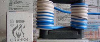
Safety resistor
A safety resistor is a special case of a conventional fuse link. It looks and behaves like a regular resistor - it has a certain resistance, tolerance and permissible power dissipation. Fusible resistors are often made in the form of radio elements with a permissible power of 0.5 W, 1 W or 2 W.
They differ from conventional resistors in that when the permissible power is exceeded, they burn out and cut off the current in the circuit without creating a fire hazard (they do not ignite themselves and reliably disconnect the circuit - which is not obvious in the case of a conventional resistor). Therefore, they behave like time-delay fuses with a certain resistance and power. True, their operation time is longer than that of a conventional fuse.
Fusible resistors, often designated on diagrams as FR, are usually used at the inputs of pulse converters as a capacitor charging current limiter, as well as as mains fuses in household appliances, and are characterized by low resistance values, from fractions of an ohm to several ohms.
How to check the main fuse
All cars have at least one main fuse. It is usually installed on the positive terminal of the battery or in the fuse box connected to the positive battery cable.
Often the main fuse will blow if you accidentally touch the wrong battery terminal while charging a dead battery. A sign of a blown main fuse is a lack of power and lighting inside the car.
Checking the main fuse is easy and you can usually see if it's blown. If the main fuse has blown, chances are that several other smaller fuses have also blown.
Characteristics of circuit breakers
Circuit breakers are characterized by:
- rated voltage and current of the machine,
- rated current of the release (Inr),
- starting current or tripping current of the machine (Itra),
- limiting circuit breaker current (Ipra).
- own response time (t),
- protective (time-current) characteristic.
The smallest current that causes the circuit breaker to trip is called the starting current or tripping current, and setting the circuit breaker release to a given tripping current is called the tripping current setting.
A separate article on the characteristics of circuit breakers is here.
How to Test a Fuse Using a Multimeter
If you have a multimeter, then there are two ways to check the fuse.
Voltage check
The first way is to measure the voltage at both contacts (terminals) of the fuse. Small fuses have the top of both terminals protruding through the fuse body. This allows you to measure the voltage on each side of the fuse without removing it.
Set the multimeter to DC voltage measurement mode (=U). Connect the COM probe (black) to the negative or metal part of the body. Set the parking brake and turn the ignition to the ON position.
The ignition must be on, because when the ignition is off, not all fuses are supplied with voltage. Using the positive test lead (red), check the voltage on both sides of each fuse. A fuse is simply an electrical conductor.
If both sides show 12 volts, the fuse is good.
If there is 12V on one side of the fuse and no voltage on the other side, the fuse has blown.
This method works well when many fuses need to be tested at the same time.
Resistance check
If you have already pulled out the fuse but it is not clear whether it is blown or not, you can check its resistance. Resistance is inversely proportional to current. The lower the resistance, the higher the current.
Resistance is measured in Ohms. A conductor, like copper or aluminum wire, has a very low resistance (about 0 ohms). A good fuse will show 0 (or close to 0) ohms.
In other words, there must be continuity between the two contacts of the fuse. A blown fuse will show very high resistance (infinity).
To measure the resistance of any electrical equipment, it must be disconnected from the electrical circuit. You cannot measure resistance while the equipment is connected or turned on. Switch the multimeter to “Ohm” and connect the probes as in the photo.
If the fuse is blown, the multimeter shows OL, which means there is no continuity or the resistance is higher than can be measured. If the fuse is good, the multimeter shows 0 ohms.
Watch the video on how to check the fuse using a lighter or multimeter:
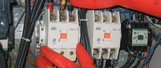
Circuit breaker design
The circuit breaker consists of a housing, contacts with an arc extinguishing system, a drive, a free tripping mechanism, releases, and auxiliary contacts.
The main elements, when triggered, turn off the circuit breaker instantly or with a time delay, are releases. The machine may have one or more releases.
Releases can be: electromagnetic instantaneous or with a time delay, ensuring selectivity of action; thermal (bimetallic); electronic maximum current instantaneous operation with a current-independent operation time or with a current-dependent time delay. minimum voltage and independent.
Watch an interesting video about slot machines below:
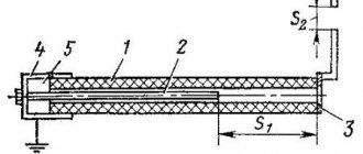
Various types of releases, conventionally shown for one circuit breaker, are presented in Fig. 2.5. A thermal or electronic overcurrent release with a current-dependent time delay provides protection against circuit overload. Thermal releases (Fig. 2.5, a) are triggered by bending a bimetallic plate 2, which receives heat from a heater 3 connected to the network through a shunt 4, and acts on circuit breaker tripping mechanism.
The protective characteristic of the thermal release is similar to the safety one.
An electromagnetic or electronic instantaneous overcurrent release with a current-independent response time provides protection against short-circuit currents exceeding 6...10 times the rated current of the electrical circuit. The type of protection with such a release is sometimes called cut-off. The electromagnetic release (Fig. 2.5, b) consists of a coil 4 and a core 5. When a short-circuit current flows through the coil, the core creates a mechanical force, which leads to the circuit breaker turning off. The tripping current of the overcurrent release can be adjusted. The release can be equipped with a time delay mechanism, dependent or independent of current.
Figure 2 5. Types of circuit breaker releases
The minimum voltage release (Fig. 2.5, c) consists of a coil 4 with a core 5 and a spring 6 and is triggered when the voltage in the circuit drops to (0.35...0.7) UNom. Such releases are used to protect electric motors whose self-starting is undesirable when power is restored spontaneously.
The independent release (Fig. 2.5, d) is used to remotely switch off the circuit breaker with button 7 and to automatically switch off the circuit when external protective devices are triggered.
How to choose the right machine, watch the video below:
What can cause a fuse to blow?
A fuse protects a circuit from higher current than the circuit can handle. If the fuse is blown, it means there is a short circuit somewhere. It can be between two wires or the power wire and ground (car body).
A fuse can also blow if the equipment draws more current than it is designed to handle. For example, if the windshield wiper or fan motor is blocked when turned on, it will draw higher current and possibly blow a fuse.
The same thing can happen if the winding inside the motor is shorted. There are several common problems that cause fuses to blow in many cars:
- The most common case is when a metal object (such as a coin) falls into the cigarette lighter socket.
- The wire harness that goes into the trunk lid frays where it bends and shorts out and trips the fuse associated with the taillights or brake lights.
- An incorrect bulb installed in one of the headlights or taillights can also cause the fuse to trip.
- Damage to trailer wiring harness.
- A wiring harness connected to any equipment inside the engine bay is wiped and shorts the fuse. For example, in some older Mercedes-Benz vehicles, it was a fairly common problem where the insulation on the engine wiring harness would crack, shorting out the wires.
Previous post Intake manifold - how it works, what malfunctions occur
Next entry Generator - how it works, problems, symptoms, testing
Purpose, design and use of fuses
What are fuses and why are they needed?
Fuses, along with circuit breakers, are used to protect elements and devices of electrical installations from damage that may occur during abnormal conditions that threaten the integrity of individual elements or the entire installation. Typically, fuses are used to protect cables, wires and electrical devices of high and low current from short circuits and more or less significant overloads.
The comparative cheapness and simplicity of the design of fuses have led to their widespread use in all cases where they are suitable for protecting electrical installations. However, being simple in design, fuses have a number of disadvantages that determine their use in electrical installations with simple switching circuits and to protect elements of installations that do not have high requirements for overload protection.
The main disadvantages of fuses are:
the difficulty, and in some cases the impossibility, of obtaining their selective action both during short circuits in the network and during overloads;
the low suitability of most fuses for protection against small overloads;
the need for a special switching device (switch, disconnector), since the fuse, unlike circuit breakers, can only perform automatic shutdown in emergency modes, being an uncontrolled device in normal modes;
the need to replace one of the parts of the fuse (fuse link) after it has tripped.
Currently, the development of fuses with more advanced characteristics is underway, allowing for reliable protection against overloads and having a higher selective effect.
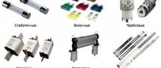
Fuses are usually classified according to the following criteria:
Currently, a large number of different types of fuses are manufactured. See more about this here: Types of fuses
The dependence of the total combustion time of the fuse-link and the extinguishing of the resulting arc on the multiplicity of the current fusing the link in relation to the rated current of the fuse insert is called the fuse characteristic, or, in other words, the ampersecond (protective) characteristic.
The characteristics of the fuse are determined by:
the ability to protect the installation element from overloads;
selectivity of the action of the fuse in conjunction with the action of other fuses and relay protection of the circuit in which the fuse is installed.
By selecting the appropriate amperesecond characteristics of the fuse links of sequentially connected fuses of adjacent sections of the network, we achieve selectivity of their action, i.e., such an action in which the insert of a fuse lower in the direction of supply blows out before the insert of a higher-level fuse has time to burn out.
When selecting fuse links according to the conditions of selectivity of protection, the condition must also be met that the rated current of the fuse link does not exceed the value determined by the rules for the protected element of the installation.
An important characteristic of a fuse is its breaking capacity, which determines the maximum value of the short circuit current cut off by the fuse. The breaking capacity of the fuse depends on the speed of extinguishing the arc when the fuse link burns out, and, other things being equal, the lower the ampersecond characteristic of the fuse link, the greater it is.
As mentioned above, the main purpose of a fuse is to protect elements of electrical installations from overloads and short circuits. A fuse connected in series with the protected element blows when the current of the protected circuit exceeds the rated current of the fuse link by a certain amount. In this case, the fuse automatically turns off the damaged section of the network. The fuse does not respond to any other deviations from the normal operation of the network. To restore power to a network section when a fuse link burns out, it is necessary to replace the burnt-out fuse link with a new one.
The main parts of any fuse are:
an element used to place (attach) a fuse-link and create conditions for extinguishing the arc when the fuse-link burns out;
fuse base in the form of a stand or socket, depending on the type of fuse, with a clamp for connection to the electric current circuit.
The base of the fuse and the element used to accommodate the fuse link are equipped with corresponding contact devices. With the help of contact devices, the element is fixed to the base of the fuse, and the reliable inclusion of the fuse-link in the protecting current circuit is ensured.
Some fuses are equipped with additional devices: clamps to prevent the fuses from falling out during vibration, handles for convenient and safe removal of the removable fuse element from the switchgear, etc.
Installation and operation of fuses
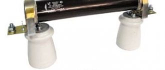
Tubular fuses must be installed on vertical planes with contact posts installed strictly vertically. It is strictly prohibited to install non-factory fuse links or inserts not intended for this type of cartridge, in order to avoid tube rupture and overlap when the fuse trips. The rated current of the fuse link must correspond to the data of the protected element of the installation.
During operation, you need to monitor the condition of fuses and distribution devices, avoiding contamination and dust, in order to avoid overlap between fuses of equal polarity. It is necessary to periodically clean the contact parts of the fuses from oxides. All operations to remove cartridges from contact posts must be carried out with specially designed devices (pliers, handles) with the voltage removed.
It is recommended to install fuses on vertical planes, but they can be installed on inclined and horizontal planes. To prevent overheating of the fuse terminals, it is necessary to carefully connect the supply wires using busbars or conductors of the proper cross-section. During operation, it is necessary to constantly monitor the correct tightening of the fuse links, turning the fuse head if necessary. It is recommended to lubricate the contact parts of the fuses with clean technical petroleum jelly.
Current strength and its effect on fuse operation
In cases where the current strength has an effective value exceeding the permissible value, the fuse operates one hundred percent.
And a personal fuse having the appropriate rating is installed in the circuit of each individual equipment.
When a fuse-link designed for a lower current strength is installed in an electrical circuit, it is capable of operating at a reduced current value.
Of course, such a fuse can provide protection to other devices, but it will need to be changed more often.
And when a fuse insert designed for a higher current strength is installed, no one can guarantee that the current passing through the circuit may be higher than allowed for the devices.
This means that these devices will simply burn out, and the fuse will not fulfill its task.
Purpose and principle of operation
The main task of fuses is to protect the electrical network and electrical equipment from overcurrents that occur during a short circuit or as a result of critical overloads. At the same time, they ensure uninterrupted operation of the protected circuits in nominal mode.
Unlike a circuit breaker, often used in electrical engineering, a fuse-link operates only once, after which it must be replaced. However, such a device works with one hundred percent probability, while the automation may fail after repeated shutdowns. That is why fusible links are used to protect expensive equipment. They do not refuse to use these protective devices in power circuits.
Design and principle of protection
The design of a fuse has two main elements: a body (holder) with contacts and a fuse insert (Figure 1). Strictly speaking, only a combination of these elements can be called a fuse. Very often the fuse link part (especially if it is replaceable) is called a fuse. In this article we will also sometimes adhere to this tradition.
Rice. 1. Fuse design
The working element of the insert is a conductor made of copper or a metal alloy. Thanks to this fusible element, circuit shutdowns occur in critical situations.
The fusible element can be one or more copper wires, a plate or a shaped part. These conductors are placed in a heat-resistant housing: glass, ceramic (Fig. 2) or plastic. Depending on the purpose, the space around the fusible element can be filled with quartz sand or surrounded by an easily evaporating substance intended to extinguish the electric arc.
Rice. 2. Ceramic fuse links
When rated currents pass through the insert wire, it heats up slightly without reaching the melting point. But in short-circuit mode, the current increases sharply, which leads to melting of the inserts. This causes the chain to break.
Heating of the fuse also occurs during overloads, that is, as a result of exceeding the rated voltage in the protected section of the circuit. When the operating voltage reaches a value called the shutdown current, the temperature of the fuse element increases to the melting point and the circuit breaks. After restoring the circuit parameters, the fuse link must be replaced.
Fuse links have a certain response inertia. With a short circuit, the delay is unnoticeable, since in this case the fuse element heats up at lightning speed.