What is a throttle and what is it for?
Fluorescent lamps, which are representatives of the type of gas-discharge lamps, cannot be lit like ordinary incandescent lamps by simply connecting the mains voltage to them. Nothing will just happen. To ignite such a lamp, a special circuit or electronic ballast is required.
If you use the simplest circuit to start a glow discharge in the bulb of a gas-discharge lamp, you will need a starter and a choke. Everything is clear with the starter. It is only required for startup, after which it is disabled. The throttle is always involved in the work. Its task is to limit the current flowing through the lamps. It may seem that a resistor is enough. It is also smaller in size. Theoretically, in an alternating current circuit, the current can be limited by a resistor, capacitor, or inductor. But unlike a resistor, it has reactance. And this makes it the most appropriate option for use as a ballast element. In the circuit it is connected in series with the lamp.
Thanks to the reactance, protection against an avalanche-like increase in current is provided.
How to make a choke for a DC welding machine
Welding with direct electric current is widely used not only in large-scale industries, but also in home workshops. The modern market offers dozens (if not hundreds) of machines for welding using an electric arc, ranging from compact low-power welders to industrial high-performance units. Regardless of the type of equipment used for electric welding, they all have one problem in common - an uncontrolled voltage drop, which makes igniting the arc and forming a seam difficult.
To solve this problem, craftsmen came up with a choke, which is introduced into the circuit with welding equipment. Beginner welders will immediately have many questions: “What is this part and how does it function? How to make a throttle for your device yourself? How to calculate the throttle correctly? In this article we will try to answer these and many other questions.
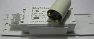
Throttle device (ballast).
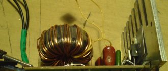
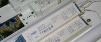
Throttle appearance
The photo shows a choke for fluorescent fluorescent lamps. By and large, it is an inductor with a metal core in a housing (casing) made of sheet metal. More modern ones are manufactured in a heat-resistant plastic case and have lower weight and dimensions. This is the industrial name (the closest translation is limiter). Its DC resistance is about 60 Ohms. When checking with a multimeter, if infinite resistance is indicated, the inductor is faulty, broken. If the resistance is less than 55 ohms, this also means the inductor is faulty. In this case, it most likely has an interturn short circuit. This happened with old ballasts when the compound began to crumble and the varnish peeled off the wire. In the simplest circuit, it serves as a ballast.
Throttle section
The inductor core is usually made of transformer steel, and the plates included in its set are not in electrical contact with each other. This is done to reduce eddy currents.
Filter choke with core gap
To reduce the drop in the magnetic permeability and inductance of the inductor with an increase in the bias current, a non-magnetic gap is introduced into the inductor core. Below are the magnetization curves of the core with and without gap.
Magnetization curves of the core material: without gap (1) and with gap (2).
As can be seen from the figure, the hysteresis loop of a core without a gap is line 1, and the hysteresis loop of a core with a non-magnetic gap is line 2. That is, curve 2 stretches and rotates relative to the zero coordinate. Thus, the inductor core, in the presence of a gap, the magnetization characteristic of which is linear, is saturated at relatively higher currents in the winding than the core without a gap.
From this we can conclude that when the bias current increases, it is necessary to select a larger non-magnetic gap to increase the inductance of the inductor.
The question arises of choosing the length of the non-magnetic gap in the core. In one of the articles I talked about how to calculate the equivalent magnetic permeability in the presence of a gap. Here the inverse problem is to calculate the length of the gap based on some given permeability, the expression will look like
where δ is the length of the non-magnetic gap, mm,
le – effective length of the magnetic field line, mm,
μe is the effective magnetic permeability of the core with a gap,
μr is the relative magnetic permeability of the core material. Since the value of the magnetic permeability of the core material is significantly greater than the required permeability μe << μr, the last term in the expression can be ignored.
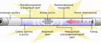
The principle of operation of the throttle.
The main thing that the inductor does is to produce a phase shift of the alternating current at the moment of transition through zero. Due to this, a glow discharge is maintained in the bulb of the gas-discharge lamp. To limit the current passing through the lamp electrodes, a choke was selected because it has reactance. In addition, any inductor can store energy.
To ignite a glow discharge, a pulse of electric current is required, this is also provided by a choke.
When power is applied to the circuit, the following occurs:
- The current flows according to the circuit through the coil, the lamp electrodes and the starter. It is relatively small, no more than 50 mA.
- Gas ionization occurs in the starter flask and the temperature rises.
- The bimetallic contacts close, the current increases to 600 mA. Further current is limited by the inductor
- This current is quite enough to heat the electrodes of the EL lamp
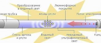
- A glow discharge begins to flow in lamp EL1 and ultraviolet radiation is generated.
- The phosphor coating, under the influence of the resulting ultraviolet radiation, begins to emit light with a visible wavelength.
It is important to remember that the parameters of the lamp and choke are correlated. Usually, making a throttle yourself makes no sense. Now there are a lot of different starting and control equipment on the market. Additionally, the choke reduces interference and smoothes out ripples.
Step-by-step scheme of work execution
The remodeling does not take much time, but it will require care. First, the source element is prepared. It is desoldered from the ballast of the electronic circuit, board. It turns out a small cube, which is torn to a w-shaped core. In the latter, two equivalent parts are installed, they are tightly fastened to each other. These devices, which are identical in size and visually similar, can be separated by simply tearing off the orange tape.
Often there is a small gap between the elements (but there may not be one). This helps slow down the magnetization of part of the core. The process leads to an increase in the speed of passage of electric current. A specialist for the manufacture of a transformer heats the core, this is done with a convenient soldering iron. For desoldering, the elements are applied to the combustible part of the instrumentation using a connecting seam.
The procedure field will open the wire in the coil. There is no need to unwind it; it is wrapped in fiberglass. This is necessary to insulate the second part of the winding. A wire of the same thickness as the winding is used. It is important that the halves removed from the core fit comfortably on it.
The secondary winding is made on the assembled parts. Installed in a convenient position and secured with tape. Only after trial testing does the final assembly take place.
Classification and types of chokes.
In different circuits, chokes can perform different functions. Let’s say that in the circuit of a fluorescent lamp illuminator it has only one task; in electronics, using a coil, you can, for example, decouple different-frequency electronic circuits, or use it in an LC filter. This determines the classification.
The type of inductor depends on its purpose in each specific circuit. These can be filtering, smoothing, network, motor, special purpose. In any case, they are united by a common property: high AC resistance and low DC resistance. This can reduce electromagnetic interference and interference. In single-phase circuits, an inductor can be used as a limiter (fuse) against voltage surges. The choke performs the smoothing function in rectifier filters. Typically an LC filter is used.
Purpose
In an inverter for welding, a choke is needed to create an electric arc on the electrode.
Ignition occurs when a certain voltage level is reached. The welding choke increases the resistance, which shifts the phases between current and voltage and allows for smoother ignition. This fact in itself often allows one to avoid burning through the workpiece, especially if parts made of thin sheet metal are welded.
A smooth change in current makes it possible to avoid damaging the workpiece by abruptly applying too much power, to optimally set the arc temperature and, accordingly, to prevent metal spattering while maintaining the required processing depth.
Another valuable property is its partial protection against unstable voltage in the network.
A choke for a welding inverter greatly facilitates ignition of the electrode, which should light up at a higher voltage than the inverter produces.
An example is the MP-3 electrode, which must have a voltage of 70 V to ignite. An output choke for welding can make working with this electrode much easier for an inverter, which produces only 48 V at idle.
This occurs due to the phenomenon of self-induction. The device induces EMF (electromotive force), which causes air breakdown and flashing of the welding arc, as soon as you bring the additive a few millimeters from the metal surface.
The choke for welding is connected to the secondary winding of the transformer in the machine. It can be used in devices of any type - both home-made and factory-made, operating on any principle - inverter, with a step-down transformer, and the like.
Connection diagram for a choke for fluorescent lamps.
Connection diagram for a choke for a fluorescent lamp
This is the simplest circuit for one light source. In the case of using two lamps, you can limit yourself to one choke, but in this case, it must withstand the total power of the two lamps.
Choke connection diagram for two fluorescent lamps
In this circuit, capacitor C1 is desirable, but it is not a required part of the circuit. Theoretically, instead of starters, you can install ordinary buttons without locking. After lighting the lamp, these buttons must be released.
Markings and symbols
In circuit diagrams and technical documentation, chokes are designated by the Latin letter L, and the conventional graphic designation is in the form of semicircles. Their number is not indicated anywhere, but usually does not exceed three pieces. A bold dot placed at the beginning of the semicircles indicates the beginning of the turns. If the inductance is performed on the frame, a straight line is drawn against the image. To indicate the denominations of an element, a code of letters and numbers or color coding is used.
You might be interested in this: Checking the diode
The numbers indicate the inductance value, and the letter indicates the tolerance. For example, the code 250 J indicates an inductance equal to 25 μH with an error of five percent. When there is only a number on the marking, this means that the tolerance is 20%. Thus, the first two digits indicate the numerical value in microhenry, and the third is the multiplier. The letter D is placed on high-precision products; their error does not exceed 0.3%.
The color marking, in principle, corresponds to the alphanumeric marking, but is only applied in the form of colored stripes. The first two indicate values in microhenry, the third is the multiplication factor, and the fourth is the tolerance. The inductance of the inductor, which shows two orange stripes, brown and white, is 33 μH with a permitted deviation of 10%.
Throttle repair.
A throttle malfunction can be determined by replacing the starter and/or fluorescent lamp with known good ones. If in this case there is no lighting, then this is the reason. A throttle malfunction can also be determined using a multimeter in resistance measurement mode. A working electromagnetic choke has a resistance of about 60 Ohms. The permissible deviation is about 10 percent. If the resistance is low, then this indicates an interturn short circuit. This happens on a throttle that has been in use for quite a long time. The reason is the peeling of paint insulation and short circuit of the turns. Infinite resistance indicates (or no continuity at all) an open circuit, lack of contact. Most likely it just burned out due to a power surge.
Remember that when working with any electrical appliances, you must follow safety precautions!
Repairing a choke for a fluorescent lamp involves disassembling: removing the casing while it is present, disassembling the core plates and rewinding the coil. However, this is an impractical process due to its labor intensity and the low price of a new one. It is easier to replace it with a known good one. When replacing, it is necessary to comply with the power parameters.
What is it: scheme of the invention
In terms of their principle of operation, the throttle and the step-down type of vehicle are similar. But visually they are easy to distinguish by the different number of windings. Only one is installed on the inductor, while on the transformer there are two or more. There is an opinion that the throttle has no clearance, but the vehicle does, or vice versa. This opinion is erroneous, since the constitutive features change depending on the resistance coefficients, therefore, the gap may be absent in both places.
The inductor transformer as an invention appeared recently. Radio amateurs noted that the first is a tool for accumulating a certain amount of energy component. In this case, inductance acts, which determines the efficiency of the device. An optimally assembled device from a choke does not serve as a source of energy storage. Its main purpose is to provide isolation for installed circuits, as well as bring voltage indicators to the required number. The function of a transformer, which is not present in the source material, is the conversion of resistances, the coordination of parameters.
Conclusions.
Although the scheme has a half-century history, it still remains relevant. Ballasts are necessary for the operation of a fluorescent lamp. All components are manufactured and inexpensive. The advantages of this scheme include its simplicity and accessibility of components. Typically, the inductor is the longest-lived component in the circuit.
Of the minuses, it was noted that when using the classic scheme, when the lighting is turned on, flickering is observed for several seconds. This has a bad effect on the useful life of the light source itself. Those. The lamp will work less in such a circuit than when using an electronic starter.
In terms of economic feasibility, if you frequently turn the light on and off, it is not profitable to use such an elemental base; it is easier to purchase an electronic starter, although its purchase will cost more, but it will be a one-time cost.
- Related Posts
- How to repair an LED strip, why it stopped lighting
- Lamps with e14 base: advantages and disadvantages
- DRL lamp 125,250,400,700 decoding and technical characteristics
Ultraviolet - we get it at home quickly and for pennies.
Nowadays, chemistry based on photocatalysts is becoming widespread. A variety of adhesives, varnishes, photosensitive emulsions and other interesting achievements of the chemical industry. Unfortunately, industrial UV installations cost a lot of money.
What should you do if you just want to try chemistry? will it fit or not? For this purpose, buying branded devices for N kilobucks is too expensive...
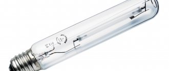
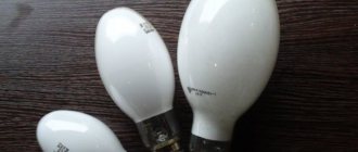
In the territory of the former USSR, the situation is usually solved by extracting quartz tubes from DRL-type lamas; there is a whole line of lamas from DRL-125 to DRL-1000, with the help of them you can obtain fairly powerful radiation, this radiation is usually enough for most occasional tasks. Like hardening the glue or varnish once a month, or exposing the photorhizist.
A lot of information has been written on how to extract a tube from DRL lamps, how to do it safely. I would like to touch on another aspect, namely the launch of these lamps with minimal financial costs.
Standardly, a special choke with increased magnetic dispersion is used for starting. But even this is not always available, and because... It’s heavy, so usually delivery to the regions costs a pretty penny. 700W throttle + delivery costs $100. What to try as an option, too, it’s never cheap.
A little theory:
The main problem with starting mercury lamps is the presence of an arc discharge. Moreover, a cold lamp and a hot lamp have fundamentally different resistance to the burning arc. Approximately from units of ohms to tens of ohms. Accordingly, this is what the inductor serves for, which limits the current during startup and operation of the lamp. It must be admitted that the choke is a rather archaic tool, and for expensive and powerful lamps used in UF dryers (several kilowatts of power, and several thousand dollars per lamp), electronic arc stabilization units are used. These blocks allow you to more accurately maintain arc burning parameters, thereby extending the life of the lamp and reducing problems during curing. Even for an archaic DRL, the manufacturer writes that the voltage spread is no more than 3%, otherwise the service life will be reduced.
How to start a DRL lamp without a choke using improvised means?
The answer is simple, you just need to limit the current in all operating modes, starting with warming up and ending with operating mode. We will limit it with a resistor.
But since the resistor must be very powerful, we will use the heating devices available at hand (incandescent lamps, irons, kettles, water heaters, hand boilers, etc.) It sounds funny, but it will work and fulfill its purpose.
The only drawback is the excessive consumption of electricity, i.e. if we run a 400W DRL lamp on the ballast, about 250W will be released into heat. But I think for the task of trying ultraviolet light, or for occasional work it is not important.
Why didn't anyone do this?
Why no one, there are DRB lamps that use exactly this principle. Next to the quartz tube is the filament of a regular light bulb.
And the writers on the Internet apparently didn’t study physics at school. Well, of course, one more small nuance, you need a heating circuit, i.e. We heat the lamp with one resistor and switch it to operating mode with the other. But I think many people can cope with a switch and two wires
So the diagram:
So, for many, I tried to depict the correct schemes, this is a dark forest, in pictures. More close to life.
How it works?
1) Warm-up phase, the switch must be open!!! We turn on the lamp into the network. The incandescent lamp begins to glow brightly, the tube in the DRL lamp begins to flicker and slowly flare up. After 3..5 minutes, the tube in the lamp will begin to shine quite brightly.
2) Secondly, we close the switch to the main ballast, the current will increase further and after another 3 minutes the lamp will return to operating mode.
Attention in total to the load of lamps + irons, kettles, etc. will release powers comparable to the power of the lamp. For example, the iron may be turned off by the built-in thermal relay, and the power of the DRL lamp will decrease.
For most, such a circuit will be very complicated, especially for those who do not have a device for measuring resistance. For them, I simplified the diagram even more:
Starting up is simple, unscrew the lamps, leave only the required amount (1-2 pieces) to start the burner, and as it warms up we begin to screw it in. For high-power DRL lamps, tubular halogen lamps can be used as a resistor.
Now the hard part:
Probably, many have already realized that lamps and loads need to be selected somehow? Of course, if you take some kind of iron and connect it to a DRL-125 lamp, there will be nothing left of the lamp, and you will get mercury contamination. By the way, the same thing will happen if you take the choke from the DRL-700 for the DRL-125 lamp. Those. The brain still needs to be turned on!!!
A few simple rules to save your nerves and health
1) You can’t rely on device nameplates; you need to measure the actual resistance with an ohmmeter and make calculations. Or use it with a safety margin, choosing a little less power than possible.
2) It is useless to measure the resistance of incandescent lamps; a cold spiral has 10 times less resistance than a hot one. Incandescent lamps are the worst choice; you have to navigate by the inscription on the lamp. And under no circumstances do you turn on the load of incandescent lamps at once; screw them in one at a time, reducing the surge current. Since I suspect that this will be the most popular way to turn on a DRL lamp without a choke. I made a video as an example.
3) For general reasons, to start heating the DRL lamp, use a load not much greater than its rated power. For the example of DRL-400, use 300-400 watts for warming up.
Table for different lamps:
| Lamp type | V-arch | I-arcs | R-arcs | Ballast resistor | Inscription on the ballast\iron\lamp\heating element | Heat on the ballast during operation |
| DRL-125 | 125 V | 1 A | 125 Ohm | 80 ohm | 500 W | 116 W |
| DRL-250 | 130 V | 2 A | 68 Ohm | 48 Ohm | 1000 W | 170 W |
| DRL-400 | 135 V | 3 A | 45 Ohm | 30 ohm | 1600 W | 250 W |
| DRL-700 | 140 V | 5 A | 28 Ohm | 17 ohm | 2850 W | 380 W |
Comments on the table:
1 - name of the lamp. 2 – operating voltage on a heated lamp. 3 – rated operating current of the lamp. 4 – approximate operating resistance of the lamp in a heated state. 5 – ballast resistor resistance for full power operation. 6 – approximate power written on the nameplate of the device (heating elements, lamps, etc.) that will be used as a ballast resistor. 7 – power in watts that will be released on the ballast resistor or a device replacing it.
If it's difficult or you think it won't work. I made a video, using a DRL-400 lamp as an example, I run it with three 300W lamps (they cost me 30 rubles each). The power on the DRL lamp turned out to be about 300W loss on incandescent lamps 180W. As you can see, there is nothing complicated.
Now the fly in the ointment:
Unfortunately, using DRL lamp burners in commercial applications is not as easy as it seems. The quartz tube in DRL lamps is made based on calculations of operation in an inert gas environment. In this regard, some technological simplifications in production have been introduced. Which immediately affects the service life as soon as you break the outer lamp cylinder. Although, of course, taking into account the cheapness (Watt/ruble), it is not yet known that specialized lamps, or constantly changing emitters from DRL, are more profitable. I will list the main mistakes when designing any devices from DRL lamps:
1) Cooling the lamp. The lamp must be hot, cooling is only indirect. Those. It is the lamp reflector that needs to be cooled, not the lamp itself. The ideal option is to put the emitter into a quartz tube, and cool the outer quartz tube, and not the emitter itself.
2) Using a lamp without reflectors, i.e. They broke the flask and screwed the lamp into the socket. The fact is that with this approach the lamp does not warm up to operating temperatures, there is severe degradation and a reduction in service life by a thousand times. The lamp must be placed in at least a U-shaped aluminum reflector to raise the temperature around the lamp. And at the same time focus the radiation.
3) Fighting ozone. They install powerful exhaust fans, and if the flow goes through the lamp, then we get cooling. It is necessary to develop indirect ozone removal so that the air/ozone intake goes as far as possible from the lamp.
4) Clumsiness when cutting the base. When obtaining the emitter, you must act as carefully as possible, otherwise microcracks in the places where the conductors are connected to the lamp will depressurize it within ten hours of burning.
A very common question about the emission spectrum of a quartz bulb from DRL lamps
. Because some chemical manufacturers write the sensitivity spectrum of their photoinitiators.
So the UV emitter of the DRL lamp is located at the midpoint between high and very high pressure; it has several resonances in the range from 312 to 579 nm. The main resonance spectra look something like this.
I would also like to note that most available window glass will cut the spectrum of the lamp from the bottom to 400 nm with an attenuation coefficient of 50-70%. Take this into account when designing exposure, curing, etc. installations. Or look for chemically pure glass with standardized transmittance values.
I would like to remind you to use protective equipment when working with UF radiation, here are a couple of videos for you to watch.
First video. We pay attention to the alien carrying prints to drying with the cover removed, this is how you have to protect yourself from UF radiation.
The second roller is a hand-held varnish dryer. Unfortunately, it is not said that an exhaust hood is needed, ozone is not very useful...
Well, it’s not scary yet, then let’s move on. But what about the poor printers/silk screen printers who decided to try modern UF inks? The prices from branded dryers are breathtaking, and if you convert them into rubles, they are simply outrageous.
I think many people tried to dry DRL with tubes, and nothing worked, well, except for some types of varnish.
In general, to be continued.
Read my reviews about printers and other equipment on my website and stay tuned for updates.
Marking of small devices
Devices for electronic boards have dimensions of no more than 2-3 cm. It is almost impossible to apply readable markings in digital or letter designations. For this purpose, color coding of electronic chokes is used. Chokes in the diagrams are depicted in the form of a spiral with a parallel line.
Several colored rings are applied to the cylindrical body of the radio component. The first two bars (from left to right) indicate the inductance value, measured in mHenry. The third bar indicates the multiplier by which the inductance number should be multiplied. The fourth ring expresses the permissible deviation in % from the nominal value. If it is not on the body of the part, then the tolerance is considered to be within 20%.
Color coding table
For example, the colors of the rings are in the following order: brown, yellow, orange and silver. This means an inductance value of 14 mH, where the deviation tolerance is 10%.
Technological progress does not stand still. Every year new analogues of outdated models appear. The development of new technologies in all areas of human activity requires the improvement of radio components, including chokes.
Materials for production
The choke for retrofitting a semi-automatic device or inverter can be assembled with your own hands, using structural elements from old equipment - tube TVs, old street lamps and other devices that have a transformer.
Structurally, it consists of a core made of a material that conducts a magnetic field, but does not conduct electric current, or is reliably insulated, and three layers of windings separated by a dielectric.
As a basis for the core, either a special material is suitable - ferrite, which has these properties, or a yoke (horseshoe) from an old transformer. Winding of the device for welding is done with aluminum or copper wire with a cross-section of 20-40 mm.
If aluminum is used, the wire cross-section must be at least 36 mm; copper wire can be thinner. A flat copper busbar with a cross-section of 8 mm is suitable.
The dimensions of the core should allow winding approximately 30 turns of a busbar of a given section, taking into account dielectric spacers. A core from the step-up transformer of the Soviet TV TCA 270-1 is recommended.
Main characteristics
In most cases, chokes have significant dimensions. To make devices compact without compromising technical characteristics, the inductor is replaced with a stabilizer, which is essentially a powerful transistor. The result is an electronic throttle. However, a device of this type is a semiconductor, so it is not practical to use it in high-frequency devices.
The electronic choke must be selected according to several parameters, the main one of which is inductance, measured in H. Also important technical characteristics of the devices are:
resistance, which is taken into account with direct current; voltage change within acceptable limits; bias current – the nominal value is used.
When choosing a device, first of all you need to focus on goals and objectives, for which you need a choke in electrical circuit diagrams. The use of magnetic cores in electric chokes makes it possible to ensure compactness of the devices while maintaining the same inductance values. Ferrite and magnetodielectric compounds, due to their low capacitance, can be used in wide frequency ranges.
Variety of choices
To choose the right ballast for fluorescent lamps, you need to know the advantages and disadvantages of existing models on the market. As mentioned above, today the following types of products are distinguished:
- electromagnetic. An electromagnetic type device is found in conventional ballasts.
- electronic throttle. It is also called an electric throttle. Today it is considered a more advanced option. They are used in electronic ballasts;
Let's look at these types of products in more detail. A feature of light sources that use electromagnetic types of throttling devices is their low cost, as well as simple installation and operation.
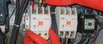
Electromagnetic ballast
However, their disadvantages far outweigh these advantages. The disadvantages of electromagnetic chokes include the following:
- bulky size;
- creating noise during operation;
- there is a strobing effect, which can negatively affect the quality of lighting;
- Such ballast consumes approximately 25% of the power.
Therefore, such devices are often used to create street lighting.
Note! All of the above disadvantages are not contained in the electronic choke, which is used in electronic ballasts.
Electronic ballast
Today, it is electronic ballasts that are most often used to turn on fluorescent lamps. Electronic ballasts began to appear en masse about 30 years ago, and today they have almost completely replaced electromagnetic types of ballasts and ballasts. This is due to the fact that electronic ballasts have the following operational advantages:
- increased luminous efficiency, which became possible thanks to high-frequency discharge;
- The strobing effect is minimized. This made it possible to significantly expand the scope of application of this type of lighting fixtures;
- no noise;
- no false starts;
- increase in service life;
- energy consumption decreased by approximately 30%;
- The efficiency is approximately 97%;
- there is no need to compensate for the reactive load.
Note! Some electronic ballast models have the ability to control the power of the lighting source. This became possible thanks to frequency regulation in the voltage converter.
As you can see, according to its characteristics, electronic ballasts are the most advantageous type of device for fluorescent lamps. Therefore, it is this type of ballast that should be chosen for the internal structure of fluorescent light bulbs.