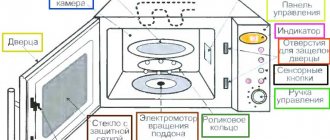
If your car's electrical equipment fails, you need to know how to check the fuse with a multimeter. Every year modern cars receive more and more additional equipment that runs on electrical power from the on-board network. To protect consumers from short circuit currents and other problems, the circuits are equipped with protective elements called fuses. If the current consumption significantly exceeds, the fuse blows, thereby eliminating the possibility of a fire in the wiring or installed equipment.
How to check a fuse in a car with a multimeter,
You also need to know because in some cases replacing it does not eliminate the malfunction; the circuit needs a more thorough check. Usually its failure is visible to the naked eye, but in some cases the break can be detected only after an instrumental check. To do this, use a car tester or even a simple voltmeter to measure direct current.
A few words about fuses
At its core, it is an ordinary wire, only of a certain thickness, which depends on the amount of current passing through this circuit. Its diameter is selected in such a way that if the calculated value of the current passed is exceeded, the wire will burn out. Thus, it is possible to avoid a possible fire in the electrical equipment of the protected objects. Such objects can be not only cars, but also residential buildings, industrial installations, and other objects where electrical energy is used.
For a long time they were a glass cylinder, hollow inside. A wire was laid inside it, which was soldered to metal tips. They are designed to provide contact with the protected circuit. Then they became widespread with ceramics instead of glass. A conductor and contacts for connection are laid on top of it.
Further improvement of these products led to the fact that they began to be made in the form of a kind of plug with flat knives for connection. This made them more reliable and practical, they received a modern look. There is an inscription on the plastic top part that indicates the current strength, but to simplify they are also painted in different colors:
- Thus, for protective devices that carry a current of 30 Amps, the color is green;
- Those intended for a current of no more than 25 Amperes are painted white;
- Yellow color is 20 Amps;
- Blue color is assigned for 15 Amps;
- The red color corresponds to a current strength of 10 Amps and so on.
Fuses also vary in size and can be large, medium or small.
Design
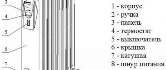
The most common tube fuses consist of:
- Porcelain body (1) with quartz sand (3);
- Plate-type fusible elements located inside the housing (4);
- Contact knife (2);
- Covers (5);
- Contact posts (6).
Diagram of the design of a tubular element.
The plates that must melt are attached to the disk near the lids of the device. Contact with the electrical circuit is made through contact legs and contact posts. Sand, which is poured into the housing, helps to quickly extinguish the electric arc that occurs when the insert burns due to a surge in current.
About voltage testing
The measuring device is switched on to voltage measurement mode and the measurement limit is set to approximately 20 Volts. This will be quite enough for the car’s on-board network, which is 12 Volts. To check, you must turn on the electrical equipment whose circuits are protected by the fuse being tested. One probe of the measuring device should be connected to the ground of the machine, and the second should measure the voltage on the fuse legs.
The measurement result could be like this:
- There is food on both legs;
- Voltage is present at the input of the protective device;
- The readings on both legs are zero.
- The last two cases will confirm the fuse is faulty.
Checking the current strength
. For such a measurement, the meter is switched to the DC current measurement mode. However, it should be warned that it is not always possible to make measurements in this way. Some circuits may carry a current that is significantly greater than the maximum limit of its measurement.
To check, the measuring device should be connected in series with consumers. If the device shows the current strength in the circuit, the fuse can be considered serviceable; if it is missing, the cause of this phenomenon should be determined.
You won't always be able to tell whether a fuse is blown or not just by looking at it. It is necessary to measure its resistance. If the fuse has zero resistance, then it is good and working properly. If there is no resistance, this means that the electrical circuit is open and the fuse has blown. Fuses come in different shapes and sizes, but they can all be tested for resistance in the same way. You can choose any multimeter to perform the test. For this demonstration we will use arrow and digital models. When using a dial model, first turn the dial to the position that measures the minimum resistance value in ohms. Calibrate the device by pressing the probes together and using the adjustment knob until the needle points to zero. When using a digital model, first turn the dial to the minimum resistance measurement position with a beep if your meter has this option. Before you begin, make sure the fuse you are testing is removed or disconnected from the appliance. Now press one probe to one contact of the fuse, and press the second probe to the other contact. If the device shows a resistance of zero ohms, the fuse is intact. If the tester's needle does not move or the digital display does not change readings, the resistance is very high, which means the fuse has blown and needs to be replaced. Be aware that a failed fuse often indicates a short circuit in the appliance's electrical circuit. For example, a short circuit of the heating element. _
Video.
For many car owners, the relay turns out to be a very incomprehensible thing. The failure of various equipment may depend on its malfunction, so you need to know how to check the operation of the relay.
To understand the operating principle of this device, it is worth reading the very detailed article How relays work in a car. In short, there is a small electromagnet installed inside the relay housing. When voltage is applied to its contacts, it attracts a jumper and closes the power line contacts - the equipment turns on. Based on this, there are some relay malfunctions that can lead to its failure.
When troubleshooting any equipment connected via a relay, you need to check whether it is working. In modern cars, relays are mounted in mounting blocks, so they will be based on this. If you have a "free-standing" relay, the testing principles are the same.
Checking the presence of power at the control contacts
When certain conditions necessary to turn on the equipment powered by the relay are met (for example, when the headlights are turned on from the interior), the relay should operate. If there is a click, skip straight to the next section of the article on power contacts. If there is no click, you need to check the voltage at the control contacts. You can determine the presence of voltage using a conventional test lamp or multimeter. Also, the multimeter can show low voltage, which the light bulb “will not notice.”
To measure the voltage at a relay contact, in some cases it is enough to slightly pull it out of the mounting block socket and touch one of the control contacts with a test lamp or multimeter probe. Therefore, the second probe must rest against the metal of the housing. However, it is safer and easier to completely pull out the relay and insert the probe into the desired slot on the block.
If there is no voltage at any of the control contacts, the relay will not turn on and, most likely, is not responsible for equipment failure. You must look for the reason why the current is not reaching the relay.
In order for the magnet inside the relay to work, in addition to the “plus” there must also be a “mass”, that is, a connection with the body. You can check its presence using the same “control”. Place one lamp probe on the positive pole of the battery, and the other in the ground socket of the mounting block. Just do not connect these places with a regular wire - this will lead to a short circuit! A light bulb or multimeter will eliminate this danger and indicate whether the appropriate outlet is grounded.
We check the presence of voltage at the power contacts of the relay
If the relay operates, this means that the electrical control circuit is working, the magnet is activated and the jumper is moving. In this case, it is necessary to check the presence of voltage at the power contacts of the relay. There is always voltage on one contact, and on the second it should appear when the relay is turned on. With the equipment turned off and connected through the relay under test, locate the power contact that is receiving voltage. To do this, insert a test lamp or multimeter probe into the corresponding socket of the mounting block, and the other end into the body.
If there is no voltage at any of the power contacts, then the power line is faulty and the relay has nothing to do with it. The reasons for power line failure can be different, but first you should check the fuse. If there is voltage at one of the power contacts of the relay, then when the relay is turned on (the relay clicked, there is voltage at the control contacts), there should be voltage at the second power contact.
If the relay is turned on and there is voltage at only one power contact, no current flows through the relay contact group. This usually happens due to burnout of the jumper contacts that close the power line. Replacing such a relay with a new one is easier, since disassembling this structure and trying to clean the jumper is a rather complicated and unreliable task. In addition, the cost of most relays is low.
Automotive fuses and their classification
On a car, most fuses are located in blocks. Most often there are two or more fuse boxes on a car. One of them is located under the hood or in the luggage compartment area. It is called the main one and includes the largest number of fuses. The other unit is located under the front panel in the passenger compartment, but in different places for all cars. Also, fuses can be located separately throughout the machine - 1, 2 or 3 pieces.
Automotive fuses are classified according to two parameters - size and rated operating current.
When choosing a car fuse, you should pay attention to the size:
In addition to the size, when purchasing a fuse, you should know its current rating. Most often, elements are installed in cars that have a rated current of 5 to 30 A. The easiest way to determine the fuse current is by its color, and below is a table that shows how the color and rated current of the fuse are related.
Types and characteristics
Depending on the element base used, relay regulators are divided into the following types:
- Microcontroller or microprocessor based. Their peculiarity lies in the inclusion of a working algorithm in the built-in chip. Used in expensive cars, such as BMW or Audi.
- Relays are based on switching relay contacts to cut off and stabilize the performance of the electrical network.
- Integrated relays are widely used in the automotive industry. The operating principle is based on solid-state switching parts or integrated semiconductors.
- Hybrid transistor-relay devices and simply transistor ones are based on semiconductor elements. They were actively used in industry until the early 90s.
Based on their design, they are divided into the following types:
- External relays are separate devices that are installed on body structures.
- Built-in switching parts are an integral part of generators.
- Combined or hybrid. Their peculiarity lies in their combination with the brush assembly of an electric generator.
An electric relay can be two-, three- or multi-level, divided into “+” and “-”.
How to check fuse resistance? About cars and motorcycles
You need to remember that fuses are in the electrical circuit, so you need to take precautions:
Expert opinion
It-Technology, Electrical power and electronics specialist
Ask questions to the “Specialist for modernization of energy generation systems”
How to ring a board with a multimeter and check the motherboard with a tester At the moment, all fuses are made with a transparent plastic case, that is, the thread located inside is visible to the naked eye. Ask, I'm in touch!
How to check a fuse in a car
If a circuit in a vehicle is overloaded, one or more fuses will interrupt the circuit and fail. However, if an electrical device stops working, it is far from certain that the problem is in the fuse. In this case, the right solution would be to diagnose the element in the fuse box that is responsible for a specific electrical device.
It is easy to determine which fuse has failed using the car's instructions. It contains a “map” that shows where the elements responsible for a particular electrical device are installed in the fuse box. This map determines the location of the fuse, due to which the circuit of the electrical device could be de-energized, and then it is necessary to diagnose it. In modern cars, the card is located directly on the fuse box cover.
Operational safety
Sometimes, not all lm324 channels are used in a project. If this is the case, then the unused ones should be connected in such a way as not to affect the others. See the manufacturer’s datasheet for options for connecting unused channels.
Under certain conditions, the polarity of the output voltage may become inverted, which may damage the chip. This is typical in comparator and voltage follower circuits. In order to avoid the appearance of negative voltage (phase inversion) at the input, manufacturers recommend adding a resistor in series to the non-inverting input of the circuit, which will limit the input current to 1 mA or lower. This amount of input current will reduce the risk of damage to the device.
All op amp inputs should not be directly connected to ground. It is always necessary to add some resistance to limit the current to 10 mA or less. All input pins must include a diode from input to Gnd. In circuits with two power supplies, the Gnd pin will be negative. However, during power-on, power-off, or when there is a sudden voltage fault, the Gnd pin may become positive. If this happens, a large current will flow through the grounded input pin, which can damage the chip.
Adding a series resistor from 1 kOhm to 10 kOhm at the input can prevent it from breaking. Do not connect to a power source with reverse polarity, as the lm324n may overheat and fail.
Manufacturers
Below are the datasheets of the main lm324 manufacturers:
Manufacturer of the Russian analogue of the electronics and communications microcircuit.
Source: shematok.ru
Visual inspection of the fuse
It is believed that the surest way to check a fuse is to visually inspect it for a break. To do this, the fuse is pulled out of the block and then examined in the light. If the wire inside is broken or there are burnt marks on it, then the circuit is broken due to the fuse.
This method is applicable for glass or transparent plastic fuses, which are the majority. However, the method has a significant disadvantage - it is based solely on human verification and does not have confirmation by a device. Visual inspection sometimes turns out to be erroneous, and it is better to use a tester to determine the integrity of the fuse.
Lm324 wiring diagram how it works
A DC motor with a control board was repaired; there is a problem with the motor not rotating. As with any such request, it begins with a “biased interrogation,” according to the client, it was established that this engine is installed on an industrial mixer of a bakery, where it has been running two shifts almost without interruption for several years. The specialist who services this equipment concluded that the problem is in the control board. I decided to start the repair by inspecting the engine; it turned out that the armature shaft was turning with great effort. The output bearings scattered or the commutator, brushes, after disassembling the engine, it turned out that the commutator was burnt out, I had to send it in for rewinding. To check the control board, I loaded it with a 100W light bulb, connected it to the network, and by rotating the resistor knob the brightness changes, which means the unit is working. Unfortunately, the experiment did not convince the customer that the board was working. We decided to check the correctness of my conclusions when the repaired engine arrives. Interest in how it works this time overcame laziness, I decided to draw a diagram using the tracks of the printed circuit board and the radio components connected to them. A diagram and a brief description, as far as I understand the purpose of the nodes, are attached below. The voltage indicators and oscillograms given in the article were taken with the working engine connected and the rotation speed knob in the middle position. The power part of the circuit is assembled using BT151-600 thyristors in a bridge circuit, the load of which is a 220V 1.8A DC motor, the control and protection circuit is made using an LM324 operational amplifier. U1.1 LM324 – current protection. As the current consumption by the engine increases, the voltage across the measuring resistor R1 at output U1.1 increases, the voltage becomes zero, diode D17 blocks the operation of the generator. It is possible to check the protection if you change the resistance of the resistor R1 0.1 Ohm by 0.5...0.9 Ohm. U1.2 - voltage feedback amplifier. The sensor, as for current protection, is resistor R1. You can check the unit if you disconnect the motor wire from the “+” contact of connector J2 (WJ25C_2), the voltage at pin 7 of U1.2 should be close to zero. It is possible that by short-circuiting resistor R1 the effect will be the same as described above with disconnecting the wire. U1.3 – engine speed adjustment with feedback adjustment of the generator comparator. The operation of the unit is checked; if there is no engine speed adjustment, when you turn the resistor R16 adjustment knob at pin 8 of U1.3, the voltage should change. It is possible to check the feedback if you connect a 47k resistor in parallel to R31 at pin 8 of U1.3 and the voltage increases. U1.3,Q1,Q2 – thyristor control pulse generator. It is advisable to check this node with an oscilloscope, but if it is not there, you can measure it with a voltmeter by comparing it with the data given in the table of voltages at the LM324 terminals. All measurements and recorded oscillograms were carried out relative to the minus of capacitor C1. Power supply to the control circuit - parametric stabilizer R2-R5, D13, D5, C1.
Source: vinratel.at.ua
How to check a fuse with a multimeter
To test a circuit element, a common device is used - a multimeter, also known as a tester. The device is indispensable for the car enthusiast, and it allows you to check the car fuse in two ways.
Voltage test
To diagnose a faulty fuse in a car circuit, you must:
Take a multimeter and set it to voltage measurement mode;
- Next, turn on the car circuit with which problems are observed - light, heater, mirror heater or another;
- After this, check the voltage at one terminal of the fuse responsible for this circuit, and then at the other terminal;
- If there is no voltage at one of the terminals, the fuse has blown and will need to be replaced.
This method is good for its simplicity, and in just a few seconds it allows you to determine if there is a problem with a fuse or other element connected to the circuit. However, it also has a disadvantage; using this method it will be difficult to measure the fuse voltage in some circuits, for example, a door lock or an audio signal. It is easier to do this using the second method described below.
Resistance test
A faulty fuse can be diagnosed by its resistance. To do this, you need to remove the element from the machine and switch the multimeter to the mode for measuring electrical resistance (Ohms). After this, the tester leads are connected to the fuse terminals, and if zero electrical resistance is displayed on the screen, it means the element is faulty and needs to be replaced.
It is believed that a failed fuse can be replaced with a wire that can restore the electrical circuit. This is true, but this method of “repair” is extremely undesirable. By installing a wire in place of the fuse, the motorist does not solve the problem, but only complicates it. In emergency cases, this is acceptable, but if you “ride on a wire” for a long time, the car’s electrical wiring will begin to melt, which can result in expensive repairs.
Methods for testing board parts with a multimeter
A situation often arises when a household appliance stops working due to a small, insignificant part that has failed. Therefore, many novice radio amateurs would like to know the answer to the question of how to ring a board with a multimeter. The main thing in this matter is to quickly discover the cause of the breakdown.
Before performing an instrumental test, it is necessary to inspect the board for damage. The electrical circuit of the board must be without damage to the bridges, the parts must not be swollen or black.
Here are the rules for checking some elements, including the motherboard.
Checking individual parts
Let's look at a few parts, if they break, the circuit breaks down, and along with it all the equipment.
Resistor
This part is used quite often on various boards. And just as often, when they break down, the device malfunctions. It is easy to check resistors for functionality with a multimeter. To do this, it is necessary to measure the resistance.
If the value tends to infinity, the part should be replaced. Part malfunction can be determined visually. As a rule, they turn black due to overheating. If the value changes by more than 5%, the resistor requires replacement.
Diode
Checking the diode for malfunction will not take much time. Turn on the multimeter to measure resistance. Red probe for the anode of the part, black for the cathode - the reading on the scale should be from 10 to 100 Ohms.
What to do when a fuse blows
Novice motorists are naturally interested in what they need to do in situations when a car fuse blows.
Remember that the cost of these elements is significantly lower than the price of the equipment they protect. These are actually cheap consumables. You can purchase them as a whole set and always keep them on hand in case problems arise, the old device burns out and requires replacement.
Don't worry if the fuses blow. This is an absolutely normal situation for any car, regardless of the make, model, year of manufacture, etc. That is, this happens both on old cars and on brand new expensive foreign cars. No electrical circuit has 100% protection against current and voltage surges.
But you need to react completely differently when burnout becomes regular and constantly repeats even after replacing components. In such a situation, you should diagnose the car and check what is wrong in the electrical system. Moreover, it is strongly recommended to begin diagnosis as soon as possible after the first symptoms are detected.
If you installed a new fuse and it burned out almost immediately, then the car owner's task is to identify the source of the problem. To achieve the desired result, a number of activities should be carried out:
- Using the technical documentation for your vehicle, check which devices and equipment are connected to the problematic fuse. These instructions must indicate which fuse does what;
- now you need to turn on all systems and equipment for which the constantly burning protective element is responsible;
- take a screwdriver, the handle of which must be insulated. Use a metal part to touch the terminals on which the fuse is attached in or outside the block;
- if a spark occurs at the moment of contact, there is some kind of malfunction in the electrical circuit;
- disconnect one of the previously switched on consumers, and then repeat the manipulations with the screwdriver;
- when, after turning off the next device, the spark disappears, this will allow you to determine the culprit. This is what causes your fuse to blow.