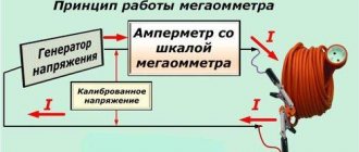
The principle of measuring insulation resistance with a megohmmeter.
The operation of the device is based on the famous Ohm's law for the circuit section I=U/R. To implement it, any modification has the following built in inside the case:
- source of constant, calibrated voltage
- current meter
- output terminals
The design of the voltage generator can vary significantly and can be created on the basis of simple hand-held dynamos, as in older models, or by using power from a built-in or external source. The output power of the generator, as well as the value of its voltage, can include several ranges or be performed with a single, fixed value. Connecting wires are connected to the terminals of the device, the other end of which is connected to the circuit being measured. Alligator clips are usually used for these purposes. An ammeter built into the electrical circuit measures the current flowing through the circuit. Taking into account the fact that the generator voltage is already known and calibrated, the scale of the measuring head is immediately calibrated in converted resistance units - megaohms or kiloohms.
This is what the scale of an old analog device, proven by fifty years of operation, looks like. It allows you to take measurements at two scale limits:
If the megohmmeter is created using new digital signal processing technologies, then its display also displays the resistance, but in a more visual form.
Megaohmmeter: principle of operation and design of the device
What is a megohmmeter, why is it called that and what is the purpose of its use? If we decipher this word, we will see that its part “mega” means the measurement value, “ohm” means a unit of electrical resistance, and “meter” means to measure. Thus, it becomes clear that a megameter is a device that tests electrical resistance.
Internal structure of the megohmmeter:
- Current generator;
- Measuring head;
- Measuring range switch;
- Current limiting resistors.
To perform a measurement, the device supplies current to the circuit being tested, and it must be constant. Alternating is not suitable here, since cable lines have capacitive reactances, and capacitors can conduct alternating current, which will lead to distortion of measurement results.
Types of megohmmeters, based on voltage:
- 100 volts – needed to check the insulation of low-voltage wires;
- 500 volts – for low-power electric machines;
- 1000 volts – for household lighting fixtures and socket modules;
- 2500 volts – for high-voltage devices and overhead lines.
The most popular models of devices are: ES0202/2G, M1101M, M4100, F4101, ESO 202/2G, electronic ut512UNI-T.
You can also ring an electric motor with a megameter to check the integrity of its windings. But basically, testing the engine or any other equipment is carried out with another device - a multimeter.
However, which device is suitable for what can be read in the technical documentation of electrical equipment.
By the way, some megohmmeters show the result after just a few seconds, while the true result is the resistance shown 60 seconds after the start of the test. Moreover, they do not have the ability to generate voltage over a long period. This is also bad, since in a short time you may not be able to see all the wiring defects.
Safety in measurements
Measurements with a megohmmeter always tell insulated conductors the charges, and the better the quality of the insulation, the longer the charge lasts. For safety reasons, be sure to remove these charges using wires with insulated handles. The connection points of the wires from the device are short-circuited and each of the conductors is additionally shorted to ground. There is only one goal - to remove all residual charges for the safety of people.
Measuring the insulation of electrical installations is easier than measuring lines and networks due to the concentration and proximity to personnel. Below is a step-by-step procedure for taking measurements on lines.
Safety regulations
Checking the cable insulation with a megohmmeter is carried out only with the equipment disconnected and de-energized.
The megaohmmeter is capable of producing high voltage (certain types up to 5000 Volts), so when working with it, strictly follow the following rules:
- ⚡personnel with the 3rd electrical safety group have the right to work with the device
- ⚡When testing, remove all strangers from the cable being tested
- ⚡before operating the device, carefully inspect its body, wires and measuring probes. They should not be chipped or damaged;
- ⚡it is recommended to measure cable insulation at positive temperatures
- ⚡do not touch the wires of the device when taking measurements
Basic rules for the safe use of a megohmmeter
Verification and testing
Any work in electrical installations may only be carried out with working electrical devices. In relation to a megohmmeter, this means that it must simultaneously meet two requirements and be:
Testing means testing the resistance of its own insulation and all components in an electrical testing laboratory with increased voltage. Based on its implementation, the owner of the device is issued a certificate authorizing the operation of the megohmmeter for a certain, limited period. Verification is carried out by metrology laboratory specialists in order to determine the accuracy class of the device and apply a stamp on its body indicating that it has passed control measurements. The owner is obliged to take measures to ensure the safety of the applied stamp with the date and number of the verifier. If it disappears, the device is automatically considered faulty.
Types of jobs
The megohmmeter is selected for each measurement primarily based on the output voltage. It can perform two different types of checks:
2. measurement of the resistance of the dielectric layer
The first method involves creating an extreme case for the test area. For this purpose, it is supplied not with the rated voltage, but with an overestimated voltage provided for in the technical documentation. The test time is also chosen to be quite long. This allows you to timely identify all insulation defects and eliminate their manifestation during operation.
The second method uses a more gentle mode. The voltage for it is selected to a lower value, and the measurement time is determined by the duration of the end of the capacitive charge of the measuring section. For electrodynamic devices, it does not exceed a minute (that’s how long you need to turn the knob at a speed of 120÷140 rpm), and for electronic devices - about 30 seconds (keep the button pressed).
For example, measuring the insulation resistance of a particular electrical circuit must be done with a megohmmeter that produces 500 volts at the output. Then to test it you will need a 1000 V device.
Insulation measurements are carried out by electrical personnel of various professions, and the testing function is provided only to specialists from the insulation service laboratory. Quite often, the capabilities of a megohmmeter for these purposes are not enough for them, and they include in their work additional installations and sources of extraneous voltage that have higher powers and measuring capabilities.
Knowledge of the features of the circuit being tested
Before applying high voltage to the area being measured, it is necessary to take measures to prevent breakdowns and malfunctions of its components. Modern electrical equipment uses many semiconductor elements, various capacitors, measuring and microprocessor devices. They are not designed for the operating conditions created by the megohmmeter generator voltage. All such devices must be protected. To do this, they are removed from the circuit or shunted in a certain way. After the measurements are completed, the entire circuit must be restored and brought into working condition.
How to connect a megohmmeter?
For each model of devices for this purpose, the output voltage value is determined, so in order to effectively test the insulation or measure its resistance, you need to choose the right megohmmeter.
Watch this video on YouTube
To check the cable insulation with a megohmmeter, a so-called extreme case is created, in which a voltage higher than the rated one is applied to the test section, but within the permissible standards specified in the technical documentation.
For example: a megohmmeter generator can produce:
- 100V;
- 250V;
- 500V;
- 700V;
- 1000V;
- 2500V.
Accordingly, the voltage supply should be an order of magnitude greater.
The duration of the measurement process usually does not exceed 30 seconds or minutes; this is necessary for more accurate detection of defects, as well as to eliminate their subsequent appearance during voltage surges in the network.
The basis of the technological process of measuring resistance is: preparation for the process, its implementation and the final stage. Each of them includes a certain list of manipulations necessary to achieve the goal without harm to others and, first of all, to oneself.
When preparing for work, you should organize your actions, study the electrical installation diagram to eliminate possible breakdowns, and also ensure your safety.
When starting work, you should first check the device for serviceability. To do this, the leads are connected to the measuring leads. Then their ends are connected to each other in an attempt to short-circuit. After applying voltage, the measurement readings are taken (they should be equal to zero). The next stage involves re-measuring. If there are no malfunctions, the reading should differ from the previous one.
Then they connect the portable grounding to the earth circuit, check and ensure that there is no voltage in the area, install the portable grounding, assemble the measuring circuit of the device, remove the portable voltage, remove the residual charge, disconnect the connecting wire, remove the portable voltage.
The final stage involves restoring the disassembled circuits, removing shunts and short circuits, as well as preparing the circuit for operating mode. The obtained results of measuring the resistance of the insulating layer are documented in the insulation verification report.
How to use a multimeter - measuring voltage, current and resistance
Resistance thermometer - sensor for measuring temperature: what it is, description and types
What is an oscilloscope for and how to measure current, voltage, frequency and phase shift
What are clamp meters used for?
What is a phase-zero loop in simple terms - measurement technique
Testing wires using a multimeter - what does it mean and how is it done?
What to pay attention to when working with a megameter
Increased device voltage
The output power of the megohmmeter generator is quite enough to not only detect the appearance of microcracks in the insulation layer, but also cause serious electrical injury. For this reason, safety regulations permit the use of the device only by trained and well-trained personnel authorized to work in live electrical installations. And this is at least the third group for TB. During measurement, increased voltage of the device is present on the circuit under test, connecting wires and terminals. To protect against it, special probes are used, installed on measuring wires with a reinforced insulation surface. At the ends of the probes, a restricted area is marked with safety rings. It should not be touched with exposed parts of the body. Otherwise, you may be exposed to voltage. To manipulate the measuring probes, grasp the surface of the working area with your hands. During measurements, well-insulated alligator clips are used to connect to the circuit. The use of other wires and probes is prohibited.
There should be no people in the entire test area during the measurement. This is especially true when measuring the insulation resistance of long cables, the length of which can be several kilometers.
Induced voltage
The energy passing through the wires of power lines has a large magnetic field, which, changing according to a sinusoidal law, induces a secondary EMF and current in all metal conductors. Its value on extended products can reach large values.
This factor must be taken into account for two reasons:
2. safety of working personnel.
The first reason is that when assembling a circuit for measuring insulation resistance, a current of unknown magnitude and direction will flow through the measuring organ of the megohmmeter, caused by the induction of electrical energy. Its value will be added to the meter reading from the calibrated generator voltage. As a result, two unknown current values are summed up in an arbitrary manner and create an insoluble metrological problem. Measuring the resistance of electrical circuits under any voltage, and not just induced voltage, is therefore generally meaningless.
The second reason is that working under induced voltage can lead to electrical injuries and requires strict adherence to safety rules.
Residual charge
When the generator of the device supplies voltage to the network being measured, a potential difference is created between the electrical equipment bus or line wire and the ground circuit and a capacitance is formed that receives a charge. After the megohmmeter circuit is broken by disconnecting the measuring wire, part of this potential is retained: the bus or wire has a capacitive charge. As soon as a person touches this area, he receives electrical injury from the discharge current through his body. For this reason, it is necessary to take additional safety precautions and always use a portable grounding device with an insulated handle to safely remove capacitive voltage. Before connecting a megohmmeter to a circuit whose insulation will be measured, it is always necessary to check that there is no voltage or residual charge on it. This is done with a tested indicator or a verified voltmeter of appropriate ratings. After each measurement, the capacitive charge is removed by portable grounding using an insulating rod and other additional protective equipment.
Typically, you need to take a lot of measurements with a megohmmeter. For example, in order to draw a conclusion about the quality of the insulation of a ten-core control cable, it is necessary to check it against the ground and each core and between all the cores in turn. For each measurement, it is necessary to use a portable grounding connection. For quick and safe work, one end of the grounding conductor is initially connected to the ground loop and left in this position until the work is completed. The second end of the wire is attached to an insulating rod and with its help, grounding is applied each time to remove the residual charge.
Tips for working with a megohmmeter:
- some people get confused with the scales of the M4100 device. Where is the measurement scale in megaohms located, and where in kiloohms? In order not to forget, use the hint: megaohm (mOhm) as a unit of measurement is higher than kiloohm (kOhm), respectively, and its scale is higher!
- Before measuring, clean the ends of the cable cores from dirt. Dirty insulation may give poor results, although the cable itself will be fine;
- The measuring leads of the megohmmeter itself must have an insulation of at least 10 mOhm. Do not use strange scraps or pieces of old wires. You will only worsen the measurement readings and will not know the exact results;
- when checking a cable in the circuit of which there is a meter, be sure to disconnect all phase conductors and the neutral conductor from the housing or busbar. Otherwise, due to the metering device, you will have megohmmeter readings as if the cable cores are short-circuiting among themselves;
- If you sequentially measure individual sections of wiring, always disconnect the neutral conductors from the common bus. Otherwise, you will get the same measurements on all cables. And these results will be equal to the worst resistance of one of the connected cables;
- if the cable is long (more than 1 km), with a large capacity, then the residual charge must be removed using a special rod. Otherwise you can create a big “boom” right before your eyes;
- When taking measurements in lighting networks, unscrew the incandescent light bulbs from the lamps and leave the switches themselves turned on. For gas-discharge lamps, measurements can be carried out without removing the lamps from their housings, but with the obligatory unscrewing of the starter.
Effect of residual stress
When the megohmmeter generator produces voltage entering the measured network, a voltage occurs between the wire and the ground loop. This leads to the formation of a capacitance endowed with a certain charge.
Once the test lead is disconnected, the megohmmeter circuit becomes open. Due to this, the potential is partially preserved, since a capacitive charge is created in the wire or bus. If this area is touched, a person may receive electrical injury from a discharge of current passing through the body. In order to avoid such troubles, you should. Its handle must be insulated, which makes it possible to safely remove capacitive voltage.
Before connecting a megohmmeter to measure insulation, it is necessary that there is no residual charge or voltage in the circuit being tested. For this, there are special indicators or a voltmeter with the appropriate rating. Using a megohmmeter you can perform a wide variety of measurements. For example, the insulation in a ten-core cable is first checked against ground, and then each core is measured. The quality of insulation is determined in turn between all cores. A portable ground should be used during each measurement.
To ensure fast and safe operation, the grounding conductor is initially connected at one end to. He remains in this position until the end of work. The other end of the conductor is in contact with the insulating rod. It is with her direct participation that grounding is applied to remove the residual charge.
How to use
To carry out tests correctly, it is important to correctly set the measuring ranges and test energy. The simplest method for doing this is to use special tables indicating parameters for different objects being tested
It is important to understand that dielectric gloves must be used during testing. It is also necessary to remove outsiders with appropriate warning posters posted
When connecting the probes, you only need to touch those parts that are insulated. Before measurement, a portable ground connection should be made to disconnect the control cables. In this case, the measurements themselves must be carried out with dry insulation until the permissible humidity limits are exceeded.
Using the device according to the operating manual ensures its correct operation and absence of breakdowns
How to ring a cable
You can check a single-core cable with several manipulations by setting the test voltage. The first probe should be attached to part of the core, and the second should be attached to the armor. After this, voltage will be applied. If there is no armor, then an earthen vein is needed. If the readings are up to 0.5 mOhm, it means the cable is not worn out and can be used further without being replaced.
Note! When calling a multi-core cable, you need to check each core, and assemble a single bundle from the remaining semiconductors. To obtain reliable results, good contact is necessary
Correct cable ringing using the device
Insulation check
Insulation testing is another function of the measuring instrument. Insulation allows you to protect the core from contact with another core. The characteristic of insulating quality is resistance. This is measured in ohms with derivatives. Resistance is the reciprocal of performance. That is, it can show the possibility of preventing the passage of electric current.
The less insulation, the greater the possibility of current finding a path and spreading from the cable to conductive surfaces and materials. That is, there may be an insulating cable breakdown
It is important to understand that insulation ages and deteriorates due to moisture and mechanical damage. Also worsens due to exposure to an aggressive external environment
Insulation check as one of the conditions of use
What is a megaohmmeter, scope of application and principle of operation
A megohmmeter is a special meter used to measure high resistance values. The main difference from traditional ohmmeters is that measurements are carried out at a significant voltage level, independently generated by insulation meters.
The functioning of insulation resistance meters is explained by Ohm's law, which operates in a section of an electrical circuit: I=U/R. The main components installed inside the housing are represented by a voltage source having a constant and calibrated value, as well as a current meter and terminal outputs.
The connecting wires are fixed to the terminals using conventional alligator clips, and the current values of the electrical circuit are measured using the ammeter present. Some models are characterized by the presence of a scale with two types of values or numbers displayed on the screen.
Operating principle of a megohmmeter
Megohmmeters are used to measure insulation resistance, as well as to determine the insulation absorption coefficient of electrical equipment that is not under operating voltage conditions. Insulation resistance meters are classified depending on the typical features of the circuit and indication method.
Digital models are cheaper devices, while analog devices are expensive, but are distinguished by high accuracy of measurements. The main area of application is currently represented by production and distribution systems of electrical energy, control systems for the operation of electrical equipment in industry, laboratories and in the field. In everyday life, such devices are not in great demand.
Types of megohmmeters
Today there are two types of megohmmeters on the market: analog and digital:
- Analog (pointer megohmmeter). The main feature of the device is the built-in generator (dynamo), launched by rotating the handle. Analog instruments are equipped with a scale with an arrow. Insulation resistance is measured through magnetoelectric action. The pointer is attached to an axis with a frame coil, which is influenced by the field of a permanent magnet. When current moves through the frame coil, the needle deviates by an angle, the magnitude of which depends on the force and voltage. This type of measurement is possible thanks to the laws of electromagnetic induction. The advantages of analog devices include their simplicity and reliability, the disadvantages are their heavy weight and significant size.
- Digital (electronic megohmmeter). The most common type of meters. Equipped with a powerful pulse generator operating using field-effect transistors. Such devices convert alternating current into direct current; the current source can be a battery or a network. The measurements themselves are carried out by comparing the voltage drop in the circuit with the resistance of the standard using an amplifier. The measurement results are displayed on the device screen. Modern models provide a function for storing results in memory for further comparison of data. Unlike an analog megohmmeter, an electronic one has compact dimensions and light weight.
Device and principle of operation
A megohmmeter is a device for checking insulation resistance. There are two types of devices - electronic and pointer. Regardless of the type, any megohmmeter consists of:
- Constant voltage source.
- Current meter.
- Digital screen or measurement scale.
- Probes, through which voltage from the device is transmitted to the object being measured.
This is what a pointer megaohmmeter looks like (on the left) and an electronic one (on the right)
In pointer instruments, the voltage is generated by a dynamo built into the housing. It is driven by a meter - it rotates the handle of the device with a certain frequency (2 revolutions per second). Electronic models take power from the mains, but can also run on batteries.
The operation of the megohmmeter is based on Ohm's law: I=U/R. The device measures the current that flows between two connected objects (two cable cores, core-ground, etc.). Measurements are made with a calibrated voltage, the value of which is known; knowing the current and voltage, you can find the resistance: R=U/I, which is what the device does.
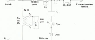
Approximate diagram of a magaohmmeter
Before testing, the probes are installed in the appropriate sockets on the device, and then connected to the object being measured. During testing, a high voltage is generated in the device, which is transmitted to the object being tested using probes. Measurement results are displayed in mega ohms (MΩ) on a scale or screen.
Megaohmmeter
Megaohmmeter - what is it?
A megohmmeter is a special device that is used by professional electricians to measure the winding resistance of electrical networks and electrical appliances. The difference between a megohmmeter and an ohmmeter is that the megohmmeter measures large resistance values at high voltage. The megohmmeter generates voltage to check resistance independently using a built-in mechanical generator or batteries. The voltage ranges from 100 to 2500 volts and is set to 100, 500, 700, 1000 and 2500 volts.
In appearance, the magohm meter is a rectangular box with an analog scale with divisions in two rows and an arrow that indicates resistance readings when measuring insulation. On the side there is a dynamo handle of the machine, which, when untwisted, generates a constant voltage, with the help of which the insulation resistance in the measured area is measured.
But we described the appearance of an analog megohmmeter; modern insulation resistance meters are smaller in size, do not have a machine dynamo, batteries are used instead, or even the power supply is connected from the mains. Instead of an analog gauge with an arrow, a digital display is used, and there is also memory for some past measurement cycles.
Why do you need a megohmmeter?
Megaommert is used to identify damage in the insulation of electrical networks before commissioning, as well as to identify the locations of emergency situations that have already occurred. For checking cable insulation in transformers, electric motors and any other devices that have an electrical winding with insulation. The main use of a megohmmeter is to measure the insulation of cables or in other words, to measure the insulation resistance of a cable.
Testing cable insulation with a megohmmeter can reveal weak points in electrical networks, both in building wiring and in electric motors. Indicators taken with a megohmmeter are used to determine the degree of wear of insulation, which can prevent unexpected and unwanted short circuits. A short circuit occurs due to mechanical damage or aging of the insulation, when the current-carrying wires come into contact with each other.
Operating principle of a megohmmeter
The megohmmeter works on the principle of generating various voltages, which are supplied to the test section of the electrical network to check the cable insulation resistance. Depending on the rated load of the device or electrical cable being measured, the appropriate voltage is used. Before testing, a suitable megohmmeter is selected, for example, if you need to check household appliances or wiring in an apartment, then a megohmmeter with a voltage of no more than 250V is used.
In simple words, the megohmmeter supplies a constant voltage to a section of the cable, which we check for normal insulation. Voltage leakage indicators are recorded and based on these indicators, conclusions are drawn regarding the standard insulation value of the cable being tested. If the leakage is greater than normal, then the insulation is considered to be damaged and there is a short circuit. Which is unacceptable during normal operation of electrical networks, because is fraught with fire of cables if the automatic switching off of contacts does not work when the cables are short-circuited.
What types of megohmmeters are there?
| Model name | Resistance measurement range | Test voltage | Device weight | dimensions |
| TsS0202-1, TsS0202-2 | from 200 kOhm to 100 GOhm | from 100 V to 2500 V | up to 1 kg. | 220x156x61 mm. |
| ES0210, ES0210-G | from 0 kOhm to 100 GOhm | from 0 V to 600 V | up to 1.9 kg. | 155x141x201 mm. |
| ES0202/1-G, ES0202/2-G | from 0 kOhm to 10 GOhm | from 100 V to 2500 V | up to 2.2 kg. | 210x150x230 mm. |
Megaohmmeters differ in external design and internal structure. Analog cable resistance meters have a dynamo machine, which, by rotating a special handle, generates a constant voltage that is used to measure insulation. There is also an analogue display with divisions on two scales and a mechanical arrow that indicates the indicators. More modern megohmmeters have power elements instead of a machine dynamo: rechargeable batteries or a direct power supply. There is a digital display that displays the measured insulation indicators and a memory that stores data from past measurements.
Each megohmmeter has its pros and cons, the analog one is larger and heavier than the digital one, but the digital one has a direct dependence on the batteries, when the analog one is always ready for work. But the choice of which megohmmeter to use is always yours.
{SOURCE}
Check the insulation resistance of the electric motor
To carry out measurements, the engine is disconnected from power. It is necessary to get to the winding terminals. Asynchronous motors operating at voltages up to 1000 V are tested with a voltage of 500 V.
To check their insulation, we connect one probe to the motor housing, and apply the second one to each of the terminals in turn. You can also check the integrity of the connection between the windings. For this check, probes must be installed on pairs of windings.
Electrical networks are characterized by various parameters. One of the most important parameters of networks is electrical insulation. Insulation is any material that prevents electrical current from flowing in the wrong direction. Insulation can be the protective sheath of wires and cables. Devices such as insulators prevent conductive lines from contacting the ground. All these measures to isolate conductive parts are aimed at preventing short circuits, fires, or electric shock to humans.
Checking the megohmmeter
Before checking the cable insulation with a megohmmeter, it is necessary to test the operation of the device itself. Here's how to do it on the M4100 megohmmeter. The device has 2 scales: the upper one for measurements in megaohms and the lower one for measurements in kiloohms.
To work in megaohms:
- ⚡connect the ends of the probe wires to the two left terminals. The probes must be open;
- ⚡rotate the knob and look at the arrow readings. If the device is working properly, it will tend to the left - towards infinity;
- ⚡ you close the probes with each other. When you rotate the knob, the arrow should deflect to the right to zero.
To work in kilo-ohms:
- ⚡ place a jumper between the 2 left terminals and connect one of the ends there. The second end is connected to the rightmost terminal. The probes are open;
- ⚡Rotate the handle and look at the readings. When the device is working properly, the arrow deviates as far as possible to the right;
- ⚡After closing the probes and rotating the handle, the arrow will tend to zero on the lower scale (i.e. to the left).
Safe operation of the megohmmeter
Any measurements should be made only with a working megohmmeter. The device must be tested in a laboratory where its own insulation and all components are checked. An increased voltage is used for testing, after which the megohmmeter is given permission to operate for a certain, limited period.
For verification purposes, the megohmmeter is sent to a metrology laboratory, where specialists determine its accuracy class. Passage of control measurements is confirmed by a stamp applied to the body of the device. During further operation, the safety and integrity of the mark must be maintained, especially the date and number of the specialist who carried out the verification. Otherwise, the device will automatically fall into the faulty category.
The correct application area also ensures safety when working with the megohmmeter. Before each measurement, the output voltage value is determined. The device is primarily used for insulation testing. For this purpose, extreme conditions are created for the area being tested, when not the rated voltage, but an overestimated voltage is supplied. The time period is also quite long. This contributes to the timely identification of possible defects and their prevention in subsequent operation.
Each circuit to be tested has its own characteristics that affect the safe operation of the megohmmeter. Therefore, before applying high voltage to the desired area, it is necessary to eliminate all malfunctions and breakdowns of the constituent elements. Modern equipment is literally saturated with semiconductors, capacitors, measuring and microprocessor instruments. They are not designed for the high voltage generated by the megohmmeter generator. Before testing, all such devices are bypassed or completely removed from the circuit. At the end of the measurements, the circuit is restored and brought into working condition.
Checking cable insulation using a megohmmeter
Insulation resistance is the most important parameter of cable performance, and as soon as the resistance drops below a certain level, the cable is considered unusable and must be replaced immediately. In this article I will talk about the reasons leading to the deterioration of insulation and how to correctly check its level using a megohmmeter.
Table of contents
Why is insulation getting worse?
Safety precautions when working with a megohmmeter.
Checking the performance of the megohmmeter.
How to understand that the insulation has become unusable.
Why is insulation getting worse?
There are a number of factors that influence the value of insulation resistance, namely:
1. Atmospheric conditions. If the cable is constantly surrounded by moisture, then even a microcrack in the insulating material will cause the insulation resistance to deteriorate sharply. That is why, in rainy weather, electrical appliances connected via a cable with poor insulation may simply not work.
2. Incorrect cable installation. If the insulating material is damaged when laying the cable, then even a new cable (if dampness forms) may show a low insulation resistance.
3. Insulation obsolescence. Whatever one may say, even the highest quality wire with extremely reliable insulation will become unusable over time due to constant exposure to the environment.
In order to identify a problematic cable in time and prevent an emergency, a device such as a megohmmeter is used to periodically check the condition.
There are both mechanical and electronic measuring instruments. Next, I will talk about the process of checking the cable with a mechanical Megaohmmeter ES0202/2-G.
Safety precautions when working with a megohmmeter
To carry out a safe inspection, the Labor Safety Rules during the operation of electrical installations (as amended by Order of the Ministry of Labor of Russia dated February 12, 2016 No. 74n) contain the following requirements:
Checking the functionality of the megohmmeter
Before direct insulation measurements, it is necessary to check the functionality of the measuring device itself. To do this, follow these steps:
— Take the device out of the case and carefully inspect its probes. You should not find any damage to the insulating material on them;
— Then we insert the probes, set the regulators as shown in the picture and scroll the knob several times and make sure that the arrow tends to show infinite resistance;
— The next step is to close the probes together (with the help of crocodiles) and also make several turns and make sure that the arrow shows a zero value;
So, having made sure that the measuring apparatus is in full working order, you can proceed to further actions.
Checking the cable insulation
1. Before checking, disconnect the cable from the electrical installation on both sides and ground it.
2. Then we connect the megohmmeter to the core being measured and the ground loop (or to two adjacent cores, if we are checking the insulation resistance between the cores), while the device itself must be installed on a horizontal surface.
Note. Depending on the position of the switch, the ES0202/2-G Megaohmmeter is capable of measuring resistance up to 50 and up to 10,000 MOhm.
3. Next, remove the grounding from the measured conductors.
4. We begin to turn the knob and monitor the indicators of the device. Moreover, if we measure a high-voltage cable, then we set the voltage regulator to 2,500 V.
If at the first limit the readings of the device go off scale, then we transfer it to the second limit and now the upper scale will be included in the readings.
5. Then we record the readings. And then, using a special jumper (an ordinary piece of wire will do), we remove the residual charge from the core being measured (connecting it to the ground) and install the grounding back.
6. All measurements of this particular core or cores are considered completed. Measuring the other ends of the cable occurs in exactly the same way. But according to the operating conditions of this megohmmeter, the break between each measurement should be equal to two minutes.
In this case, the choice of voltage for testing is regulated by the PUE, 7th edition, clause 1.8.7
How to understand that the insulation has become unusable
According to the requirements of technical documentation, the lower insulation limit after which cable replacement is inevitable is 0.5 MOhm
But for better orientation in the degree of cable insulation quality, you can use the following table
This will be quite enough to understand the degree of wear of the insulation of a particular cable.
That's all I wanted to tell you about checking cable insulation using a megohmmeter. If the article was interesting or useful to you, please rate it with a like.
How to check a megohmmeter
Before starting the measuring work, an operation is performed to check the serviceable condition of the device and its leads; for this, the wires connected to the device are short-circuited and the generator handle is rotated, the arrow should show “0”; the short circuit is in the “I” switch position. When checking, while connecting the wires, you must not touch them with bare hands, as you may receive an electric shock.
How to use a megohmmeter
or the sequence of measuring work:
- Connecting a megohmmeter to the resistance measurement sockets.
- Connecting the grounding conductor to the screen (casing) socket.
- Setting the switch to the desired measurement range, there are two of them, the higher the power of the equipment, the larger the measurement range.
- We check the operation of the device by closing the measuring probes while simultaneously rotating the handle.
- After connecting the measuring cords, rotate the handle of the megohmmeter (power generator), the speed should be at least 120 rpm.
- Moving the measurement arrow to a specific position is the start of the measurement report.
- To reduce the time it takes to measure resistance with a megohmmeter on scale II, short-circuit the resistance socket (before starting the measurement) and rotate the device knob for about 5 seconds.
- After using the megohmmeter, set the switch to the neutral position.
The permissible error in the operation of the megohmmeter is 0.05 Mohm + -15%. The additional error limit associated with the presence of industrial-frequency currents in the form of interference in the measurement circuit is about 500 μA. The device can be operated at temperatures ranging from 30 to +50 o C. At the terminals there is a measuring voltage of the megohmmeter from 500 to 2500V, depending on the measurement range used, therefore, upon completion of the measurement, it is necessary to discharge the generator by touching the “ground” with the measuring probes or short-circuit them for a second, between each other, until an electric discharge occurs.
How is the measurement made?
Measurements are made with a megohmmeter to measure the insulation resistance of cables
When measuring the resistance of power cables, you should always take into account the ambient temperature and carry them out at a temperature not lower than +5.
Such restrictions are introduced for the reason that the cable may contain moisture, which at subzero temperatures will turn into ice, which does not conduct electric current. The measurements themselves are made with a megohmmeter, which is included in the state register of devices approved for measuring cable insulation resistance and undergoes annual verification.
Before starting measurements, you should turn off the power to the line and make sure that there is no voltage on the cable being tested. The other end of the cable is disconnected from the consumer, its wires are separated to the maximum distance, and a person is placed nearby to prevent unforeseen situations. Prohibitory (“Do not turn on, people are working!”) and instructive (“Grounded”) posters are also posted. The measurement itself is carried out with a 2500 V megger for 1 minute in the following sequence:
- Resistance measurement between phase conductors: (A-B, B-C, A-C).
- Between phase conductors and zero: (A-N, B-N, C-N).
- When. if the cable is five-core, also measure the resistance between the conductors and ground (A-PE, B-PE, C-PE).
- Between zero and ground, having previously disconnected the zero from the busbar (N-PE).
Digital megohmmeter 2500 V
Upon completion of measurements, the results are recorded and compared with acceptable values, after which a protocol is drawn up, which displays:
- sequence of actions performed;
- type of means used for measurements;
- temperature regime.
At the end, a conclusion is written about the condition of the cables.
Algorithm for measuring insulation resistance of high-voltage power cables
High-voltage power cables are those with a voltage of 1000 V and above. The insulation resistance of high-voltage power cables must be at least 10 MΩ (10,000,000 Ω).
High voltage power cables
The conditions and preparation for measurements are the same as when measuring low-voltage power cables: the power supply and consumers are turned off, the air temperature is taken into account (also not lower than +5), posters are hung up and a person is left at the other end of the cable being tested.
The measurement algorithm for high-voltage cables differs from low-voltage cables; measurements here are carried out not directly between the conductors, but between the conductor and the ground, having previously grounded the other conductors.
The measurement is carried out as in the case of checking a low-voltage cable with a 2.5 kV megger in the sequence below. Each measurement should last 1 minute.
- Ground all cable cores.
- Connect one clamp of the megohmmeter to ground, the second to the wire being tested.
- Ground the tested conductor and remove the grounding from the next one being tested.
The above described actions are repeated with each tested conductor; the tested ones must be grounded, this is done for this purpose. to remove residual or induced voltage. As with low voltage cable, the data is recorded and logged.
Measuring the insulation resistance of control cables
Control cables are those that are not intended to operate in heavy-load circuits. They are mainly designed to work in secondary circuits and control various switching devices - relays, starters, as well as control and protection devices.
The insulation resistance of control cables must be at least 1 MOhm.
The preparatory work is the same as for measuring other types of cable:
- Power off.
- Checking for no voltage.
- Posting signs is mandatory!
The measurement is also carried out with a 2500 V megger using the same algorithm as for high-voltage cables, the only difference is that it is not necessary to disconnect consumers. As in previous cases, the time for measuring the resistance of each core is 1 minute. Upon completion of the measurement work, the results are also recorded, and at the end a protocol and conclusion is drawn up on the admissibility of further operation of the cable.
Cable insulation resistance standards
For cable insulation resistance, there are certain standards listed in this table:
The lowest permissible insulation resistance of secondary circuit devices and electrical wiring
Insulation resistance standards for various cables
- High-voltage power cables - resistance is not standardized, but not lower than 10 MOhm.
- Low-voltage power cables - at least 0.5 MOhm.
- Control cables - not lower than 1 MOhm.
How to measure cable insulation resistance
Most often it is necessary to measure the insulation resistance of cables. How to use a megohmmeter in this case? If the cable is already in use, it is disconnected from the power supply and the load connected to it is removed. There are several types of changes:
- Each cable core in relation to all the others, united in a bundle and connected there with an earth wire.
This is how the cable insulation condition is measured
Points 2 and 3 are performed if the results of the first measurement are below normal. These measurements are simple, but if you have lived a lot, they take a lot of time. It’s good that electricians mainly use three-core wires, and only when supplying a three-phase network can there be more of them.
How to use a megohmmeter: this is how you measure the insulation resistance between two wires in a cable
When measuring on the panel, all machines are switched to the “off” position, the load is removed, and then measurements are taken. In this case, you don’t have to remove the wires from the sockets, but touch the contact screws with probes. Be careful: the input line on the input machine (connected to the upper sockets) cannot be measured without turning off the power at the substation.
If the cable is shielded (there is a metal braid of wire, steel or aluminum tapes), install a probe with a forked tip, and the screen is added to the bundle to the wires and the “ground”.
Measurements with a megohmmeter
The measurement process itself is simple, but it must be carried out strictly following the rules and sequence of actions. During verification, high voltage is created, which can be dangerous if handled carelessly. Therefore, we carefully read the rules and strictly adhere to them.
Measuring the insulation resistance of one core to the screen
Preparing for work
Before using the megohmmeter, it is necessary to carry out preparatory work. To begin with, the circuits under test are disconnected from the load. If you measure the insulation resistance in home wiring, turn off the power using a switch or unscrew the plugs. When measuring cables of socket groups, remove all plugs from the sockets. When measuring wiring for lighting, unscrew the light bulbs from all lighting fixtures (chandeliers, sconces, spotlights). Only in this form - without load - can cables and wires be checked.
When checking the insulation resistance of home electrical wiring, turn off all devices by unplugging them from the sockets and unscrew the light bulbs
Another stage of preparation for working with a megohmmeter is connecting a portable ground. It is necessary to remove residual voltage in the measured circuits. A copper stranded wire with a cross-section of at least 1.5 square is attached to the grounding bus in the shield. Its second end is stripped of insulation and attached to a dry stick. The wire must be attached so that it is convenient for the copper to touch the conductors.
Safety requirements
At enterprises, measurements with a megohmmeter can be carried out by workers with electrical safety group 3 and higher. Even if measurements are carried out at home, you must act in accordance with safety rules. To do this, before using the megohmmeter, you need to learn the instructions. According to the instructions you need:
- Wear dielectric gloves (this point is almost always neglected, although probably in vain).
- Before starting work, prepare the lines and make sure there are no people on the line. Enterprises are required to display warning signs (“Do not turn on” and “Caution high voltage”). If you are measuring a long line, you can do the same at home - it is better to play it safe and put a warning poster on the dashboard than to treat the consequences of electric shock.
- Hold the probes by the insulated handles at all times. They have finger rests and are designed to withstand high voltage.
- Before using a megohmmeter, remove residual voltage from the line using a portable grounding device.
Do the same after each measurement. Hold probes only by insulated handles - Each time you finish measuring, connect the probes by crossing their non-insulated parts. This relieves residual voltage on the device. Some electronic models have a self-discharge function, when the residual voltage is removed automatically after each measurement. If there is no such function, do not forget to do it yourself.
- After each measurement, connect portable grounding to each conductor to remove residual voltage.
Pay special attention to residual stress. If the tested line is long, a significant charge accumulates, which can even cause lethal damage.
Connecting a megohmmeter to the line being tested
Three probes are included as standard. One of the bottoms has two tips on one side. It is used when measuring shielded cables to eliminate leakage currents (the probe with the letter “E” clings to the cable shield).
At the top of the device there are three sockets into which probes are connected. They are marked with letters:
- Z - for connecting protective grounding;
- L - line (the line being tested is connected);
- E - screen (used if it is necessary to exclude leakage currents).
How to use a megohmmeter: standard equipment for most devices
In preparation for work, single probes are inserted into sockets “L” and “Z”. This is how most measurements are made. Only if it is necessary to exclude leakage currents, use a double probe. One of its tips with the letter “E” is inserted into a socket with a similar inscription, the second into the socket “L”.
Next, using alligator clips, we connect the device to the measured line:
- If you need to measure the insulation resistance between the cable cores, we attach both probes to the bare part of the wires.
- If a “ground fault” is being checked, we attach one probe to the wire, the second to the ground terminal.
There are no other options. Except for the case described above with a shielded cable. But they are practically not used in private houses and apartments. If, after all, there is a cable with a screen and it is necessary to exclude leakage currents, we use a probe with a forked end, twist the shielding braided wires into a bundle and add them to the general bundle of measured wires.
We take measurements
Now specifically about how to use a megohmmeter. After installing the probes on the megohmmeter, you need to select the test voltage. For this, there are special tables that indicate at what voltage it is necessary to check the insulation resistance for a wide variety of devices and devices, as well as what resistance can be considered “normal”.
| Measured object | Test voltage | Minimum permissible insulation resistance value | Terms, notes |
| Electrical wiring and lighting network | 1000 V | 0.5 MOhm and above | For premises with normal operating conditions, check once every 3 years, with increased danger - once a year |
| Stationary electric stoves | 1000 V | 1 MOhm and above | Preheat the stove and turn it off, check it at least once a year |
| Electrical panels, switchgears, conductors (main cables) | 1000-2500 V | Not less than 1 MOhm | Check with each line separately |
| Devices with voltage up to 50 V | 100 V | See product data sheet, but not less than 0.5 MOhm | When measuring semiconductor products, shunt |
| Devices with voltage from 50 V to 100 V | 250 V | See product data sheet, but not less than 0.5 MOhm | |
| Devices with voltage from 100 V to 380 V | 500-1000 V | See product data sheet, but not less than 0.5 MOhm | Electric motors and other products |
| Devices with voltage from 380 V to 1000 V | 1000-2500 V | See product data sheet, but not less than 0.5 MOhm |
When checking the insulation resistance of home wiring cables, a voltage of 500 V or 1000 V is applied. The procedure is as follows:
- The object is being prepared for measurement (described above).
- Portable grounding is installed.
- The switch on the device is placed in the required position, the measurement scale is selected (based on the expected resistance value).
- The absence of voltage on the line is checked (with an indicator screwdriver or multimeter), after which the probes are connected to the objects being measured.
- The portable grounding is removed.
This is what a finished portable grounding looks like. You can do something like this
- We take measurements. On electronic ones we press the “test” button, on manual ones we turn the dynamo knob until the signal lamp lights up (this means the test voltage has been created).
- We record the instrument reading.
- We turn off the probes, remove the residual voltage on the device and the line.
If the measured insulation resistance is greater than or equal to the rated value (or what is indicated in the table), everything is fine with the device/cable. If the insulation is lower than required there are two options. The first is to look for the cause, eliminate it, measure it in a new way. The second is to replace.
Measuring the insulation of an asynchronous motor with a megohmmeter
Before measurements, turn off the power and remove the residual voltage. Then you need to gain access to the winding terminals. We attach one dipstick to the engine body. Make sure that the contact is with clean metal - you need to find an area without paint or rust. When checking, we connect the second probe to each of the windings (you also need to make sure that it is clean under the “crocodile”.
According to the table, asynchronous motors connected to a 220 V or 380 V network are tested at a voltage of 500 V.
Work with a megaohmmeter can be carried out without a work permit only in electrical installations up to 1 kV. In this article we will tell you what safety rules are required when using it.
From the article you will learn:
Design features of megaohmmeters
There are different models of megaohmmeters, but they all include a high-voltage DC source (generator) and an ammeter. The generator produces a calibrated voltage, the value of which is set in advance. For this reason, the measuring scale of the device can be immediately calibrated in units of resistance rather than current.
Types of megohmmeters
There are two main types of devices:
1. Megaohmmeters equipped with a mechanical generator. These are old-style devices that use dynamos as a voltage source. They must be actuated manually at a frequency of approximately 2 rps. They are quite large and heavy, but do not require a power source. Such devices are convenient due to their autonomy.
This is what a megohmmeter with a mechanical generator looks like
2. Megaohmmeters equipped with an electronic converter. These are new generation devices. In them, the constant voltage source is powered by built-in batteries or a power supply. Such devices are compact and lightweight, but their performance depends on the power source.
This is what an electronic megohmmeter looks like
Megaohmmeter device
A typical megohmmeter consists of a direct current generator, a measuring head, a toggle switch and current-limiting resistors. The operation of the measuring head is based on the interaction of the working and counteracting frames. The toggle switch can be set to certain measurement limits. It switches various resistor chains that change the output voltage and operating mode of the head.
All elements are enclosed in a durable, sealed dielectric case, equipped with a handle for more convenient carrying. There is also a portable folding generator handle located here. To begin generating voltage, it unfolds and rotates. On the case there is a toggle switch control lever and three output terminals to which connecting wires are connected. Each output has its own designation: “G” - ground, “L” - line and “E” - screen.
Terminals “Z” and “L” are used in all cases where it is necessary to measure the insulation resistance in relation to the ground loop. Terminal “E” is necessary to eliminate the impact of leakage currents when measuring between cable conductors located in parallel or similar current-carrying parts. Terminal “E” works in conjunction with a special test lead that has shielded ends. It is usually connected to a casing or screen. This terminal provides the most accurate measurements. In some models, terminals “L” and “Z” are designated by the corresponding markings “rx” and “-”.
The principle of operation of megohmmeters using internal or external generator power supplies is the same as that of designs with a handle. In order to output voltage to the circuit being tested, you must press the button and hold it in this state. There are devices that can produce different combinations of voltages by combining several buttons.
Modern megohmmeters have a more complex internal structure. The voltage produced by generators of different designs is approximately a range of values: 100, 250, 500, 700, 1000 and 2500 V. Some megohmmeters can operate only in one range, while others can operate in several at once.
The output power value of a megohmmeter capable of checking insulation on high-voltage industrial equipment is many times higher than the same parameter for megohmmeter models capable of checking only household wiring. Their sizes also differ markedly from each other.
The main types and brands of megohmmeter devices from my practice (design and principle of operation)
Megaohmmeter ESO-210
4. Let's start with the simple ones. So, the first participants in today's parade are the Ukrainian devices ESO 210/3 and ESO 210/3G. The letter “G” indicates that the device is powered by an internal generator and has a handle. The model without a handle operates from a 220V network and from a button. They are small in size and easy to use. These are faithful assistants to energy workers. They are convenient for testing any electrical equipment. You can also take one of the ends after the test and ground it with it, because the ends on both sides have metal tips. In models with a handle, an alternating current generator acts as a voltage source, in models with a button - a transformer that converts alternating voltage into direct voltage.
So, let's go through the device settings. The device can be tested by applying a constant voltage of 500, 1000 or 2500 Volts. The readings appear on a dial scale, which has several limits that are switched by a switch. This is a scale of “I”, “II” and “IIx10”.
Scale “I” – lower numbers of the upper scale. The countdown goes from right to left. Values from 0 to 50 MOhm.
Scale “II” – the upper numbers of the upper scale. The countdown goes from left to right. Values from 50 MΩ to 10 GΩ.
Scale “IIx10” – similar to scale “II”, however, values from 500 MOhm to 100 GOhm.
The device also has a lower scale from 0 to 600 V. This scale is available in the ESO-210/3 device and, when the voltage supply button is not pressed, shows the voltage at the ends. In general, we brought the ends of the megohmmeter to the socket, and the needle rose to 220V. But you just need to connect them correctly to measure voltage, not insulation resistance. One on the zipper and the other on the Ux.
When voltage is applied, the red light on the scale lights up, which indicates the presence of voltage at the ends of the device.
How to connect the probes of the device? We have three holes for connecting probes - a screen, a high voltage and a third measuring hole (rx, u). In general, two probes are paired and one of them is signed. It is not easy for an attentive person to make a mistake.
Megaohmmeter sonel mic-2510
Let's step further and focus our attention on a powerful Polish device called Sonel - megohmmeter mic-2510. This megohmmeter is digital. Outwardly, it is very nice, the kit includes a bag in which alligator type probes (quite powerful and reliable) and plug-in ones are folded. In addition, the kit includes a charger. The device itself runs on a battery, which is quite convenient. No network connection is required and no rotation of the knob is required, as with older models of domestic megohmmeters. There is also a tape for comfortable placement on the neck. At first it didn’t seem very convenient to me, but eventually you get used to it and realize all the advantages. In addition to a reliable battery, the advantages include the ability to supply voltage without holding the button. To do this, first press start, then “enter” and that’s it – watch the readings and don’t let anyone get under voltage.
This device can measure the following quantities using a two-wire and three-wire method. The three-wire method is used for measurements where it is necessary to exclude the influence of surface currents - transformers, cables with a screen.
The device can also measure temperature using temperature sensors, voltage up to 600 volts, and low-resistance contact resistance.
The device scale has values of 100, 250, 500, 1000, 2500 Volts. This is a wide enough range to suit engineers' needs for a wide range of testing needs. From absorption coefficient to polarization coefficient. The maximum measurable insulation resistance that the device can measure is 2000 GOhm - an impressive value.
The polarization coefficient characterizes the degree of aging of the insulation. The smaller it is, the more worn the insulation is. The polarization coefficient is 2500V and we measure the insulation resistance after 60 and 600s or after 1 and 10 minutes. If it is more than two, then everything is fine, if from 1 to 2, then the insulation is questionable, but if the polarization coefficient is less than 1, it’s time to sound the alarm. Western chief engineers do not welcome high-voltage tests, by the same AID, but are happy to conduct a vigilante test at 5 kV or 2.5 kV with the measurement of this coefficient.
The absorption coefficient is the ratio of the insulation resistance after 60 and 15 seconds. This coefficient characterizes the moisture content of the insulation. If it tends to unity, then it is necessary to raise the issue of drying the insulation. More details about its value for different types of equipment are described in the electrical equipment testing standards of your country.
In the process of work, I came across other devices, but these two show how far progress has come in the production of megaohmmeters. Each of the devices I have seen has its pros and cons.
Permissible resistance scale
As a rule, each enterprise has its own scale, depending on the equipment. The following are examples of permissible insulation resistance of electrical installations, devices, circuits and wiring:
- Electrical installation 12 watts = less than 0.5 megohms;
- Device voltage from 42 to 380 watts = less than 0.5 MOhm;
- Hand-held electric tool in the form of a transformer, portable lamp = less than 0.5 MOhm, and a voltage of 2 MOhm;
- Household stationary electric stove = 1 MOhm;
- Tap and play = 0.5 MOhm;
- Power and lighting wiring, distribution installation, panel and current conductor = 0.5 MOhm;
- Secondary control metering or signaling protection circuit = 1 MΩ or higher;
- Control circuit, power circuit and voltage circuit - 1 MOhm and above.
User manual
The insulation resistance is checked on de-energized equipment or cable lines or electrical wiring. Remember that the device generates high voltage and if the safety precautions for using a megohmmeter are violated, electrical injuries are possible, because Measuring the insulation of a capacitor or long cable line can cause a dangerous charge to accumulate. Therefore, the test is carried out by a team of two people who have an understanding of the dangers of electric current and have received safety clearance. During testing of the object, no unauthorized persons should be nearby. Remember about high voltage.
Each time the device is used, it is inspected for integrity, for the absence of chips and damaged insulation on the measuring probes. Trial testing is carried out by testing with open and closed probes. If tests are carried out with a mechanical device, then it must be placed on a horizontal, flat surface so that there is no error in the measurements. When measuring insulation resistance with an old-style megohmmeter, you need to rotate the generator handle at a constant frequency, approximately 120-140 rpm.
If you measure resistance relative to the body or ground, two probes are used. When testing the cable cores relative to each other, you need to use the “E” terminal of the megohmmeter and the cable screen to compensate for leakage currents.
Insulation resistance does not have a constant value and largely depends on external factors, so it can vary during measurement. The check is carried out for at least 60 seconds, starting from 15 seconds the readings are recorded.
For household networks, tests are carried out with a voltage of 500 volts. Industrial networks and devices are tested with voltages in the range of 1000-2000 volts. You need to find out exactly what measurement limit to use in the operating instructions. The minimum permissible resistance value for networks up to 1000 volts is 0.5 MOhm. For industrial devices, no less than 1 MOhm.
As for the measurement technology itself, you need to use a megohmmeter according to the method described below. As an example, we took the situation with measuring insulation in a switchboard (power panel). So, the procedure is as follows:
- We remove people from the part of the electrical installation being tested. We warn about the danger and post warning posters.
- We remove the voltage, completely de-energize the shield and input cable, and take measures against erroneous voltage supply. We hang up a poster - DO NOT TURN ON, PEOPLE ARE WORKING.
- We check that there is no voltage. Having previously grounded the terminals of the test object, we install the measuring probes, as shown in the megohmmeter connection diagram, and also remove the grounding. This procedure is carried out with each new measurement, since nearby elements can accumulate a charge, introduce an error in the readings and pose a danger to life. Installation and removal of probes is carried out using insulated handles while wearing rubber gloves. Please note that the insulating layer of the cable must be cleaned of dust and dirt before checking the resistance.
- We check the insulation of the input cable between phases A-B, B-C, C-A, A-PEN, B-PEN, C-PEN. The results are recorded in the measurement protocol.
- We turn off all automatic devices, RCDs, turn off lamps and lighting fixtures, disconnect the neutral wires from the neutral terminal.
- We measure each line between phase and N, phase and PE, N and PE. The results are entered into the measurement protocol.
- If a defect is detected, we disassemble the measured part into its component elements, look for the fault and fix it.
At the end of the test, we use portable grounding to remove the residual charge from the object, by short-circuiting, and from the measuring device itself, discharging the probes among themselves. According to these instructions, you need to use a megohmmeter when measuring the insulation resistance of cable and other lines. To make the information more clear to you, below we have provided videos that clearly demonstrate the order of measurements when working with certain models of devices.
Operating rules
A megaohmmeter is a dangerous device due to high voltage. Only a person who has knowledge and experience can work with it.
Only trained people who know safety precautions can start working with a megohmmeter. Work in electrical installations where the voltage is more than 1000 volts is carried out with permits, that is, a work permit. However, issuing a document for several works is not permitted. Also, working at a similar mains voltage is allowed for people who have the third and fourth electrical safety groups.
Note! Before starting, you need to check the integrity of the device. When working with the device, you must use dielectric gloves and under no circumstances touch live elements. After activity, it is necessary to remove the remaining charge by grounding.
How to inspect electrical wiring
An inspection of the electrical wiring can only be done after inspecting its integrity. So, there should be no broken, cracked or crumbled parts on the wire bends. If, after a visual inspection, no prerequisites for replacing the cable have been identified, it is necessary to measure the insulation resistance. To do this you need to use a megohmmeter.
Wiring Research
According to the rules of electrical installations, the network must not have a resistance of less than 0.5 megohms in order to correctly carry out a test with a voltage of a thousand volts.
In addition, electrical wiring is being investigated as a preventive measure. For example, insulation resistance must be checked every three years according to the rules for the technical operation of electrical installations. Where there are particularly dangerous objects and outdoor installations, inspections are done once a year.
Note! When starting work, it is necessary to calculate the total power of potential installed electrical appliances. Based on this information, it is necessary to calculate the cable cross-section based on power indicators. Next, you need to compare the resulting figure with the one equal to the cable cross-section. If it is less, then you need to urgently change all electrical wiring.
Then you need to check all hidden wiring. There should be no damage to any part of the insulation. The wires must have special terminals.
It is imperative to check the switchboard. It must be assembled correctly. Otherwise, when all electrical appliances are connected to the panel, the machine will knock out due to the maximum load.
View cable integrity as necessary before testing it