Methods
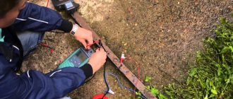
Testing methods depend on the purpose for which it is performed. To check the integrity of the cable for a break or electrical connection between its wires (short circuit), the continuity test can be done with a tester based on a battery and a light bulb, or you can use a multimeter for this purpose. The latter is preferable.
Despite the fact that the price of a multimeter is higher than a primitive device, we recommend buying it; this device will always be useful in the household.
To check the cable, the multimeter must be turned on in the appropriate mode (diode or buzzer image).
The testing methodology is as follows:
When checking a wire for a break, the tester is connected to its ends as shown in the figure. If the cable is intact, the light will glow (when testing with a multimeter, a characteristic sound signal will be heard).
Explanations for the picture:
- A – electrical cable;
- B – cable cores;
- C – power source (battery);
- D – light bulb.
If the cable has already been laid, then on one side it is necessary to connect the wires together and ring the wires at the other end;
when checking the presence of an electrical connection between the cable cores, the tester probes are connected to different wires. Unlike the previous example, there is no need to twist the wires on the other side. If there is no short circuit between the wires, the light will not light (when testing with a multimeter, no beep will sound).
Testing home electrical wiring
We will talk about an apartment in which the wiring of power lines complies with modern standards and requirements: each room has a separate line, and its power is supplied through its own “automatic machine”.
If the light in a room suddenly goes out, but in all other rooms it lights up normally, then first of all you need to check whether the light device is working. Before starting work, the power supply to the room must be turned off. If the lamp lamp is transparent, the broken filament will be immediately visible; if not, you will have to test it with a multimeter.
First you need to see whether the circuit breakers in the electrical panel have worked or not. If they are on, the problem most likely lies in the socket, switch, or the light bulb itself, and the wiring is fine. When the machine is triggered, it is necessary to check all elements of the circuit, except the switch, including the switch itself.
The machine didn't work
If the light goes out and the switch remains in the on position, then you first need to ring the switch. If it is working properly, then when the element is in the on position, the multimeter should emit a sound signal, and when it is off, the number 1 should appear on the display if there is no sound.
Further checking occurs in the following order:
- Turn the multimeter into voltage measurement mode, and then check the input and output of the switch.
- If there is a potential difference on the machine, unscrew the light bulb from the socket and touch its central contact with one probe and the base with the other. If there is no signal and the display shows 1 or 0, the lamp is faulty.
If the check shows that the light bulb is working, you should proceed to testing the socket. Having disassembled the lighting device, you need to inspect the connected conductors and contacts. If a visual inspection does not reveal any problems, the problem is not in the cartridge.
Such a check usually reveals that one of the listed elements is faulty. After replacing or repairing it, the problem disappears.
The machine worked
If the light in the room turns off along with the operation of the machine, first of all you should check the cartridge and the integrity of the cables connected to the lamp. How this is done was described above.
Damage to it occurs infrequently, but sometimes occurs, for example, when installing decorative parts or installing suspended ceilings.
The procedure for dialing the electrical line is as follows:
- Disconnect the supplied cable and move it to the side using a screwdriver.
- Unscrew the incandescent light bulb from the socket.
- Put the multimeter in dialing mode. Use one of the probes to touch the neutral wire, and the other to the end of the disconnected wire. The tester's sound signal will notify you of a short circuit in the electrical wiring.
- After making sure that there is a short circuit, you need to find and then open the junction box and disconnect the conductors in it from each other.
- Check all cable groups for short circuits. To determine a closed section, you must first ring the circuits located on the apartment electrical panel with a tester. The signal that is heard will indicate a malfunction of the conductor leading from the panel to the junction box. If it is OK, then the diagnosis continues until a damaged cable is detected.
An example of searching for a broken wire in the video:
In this material, you learned how to test wiring to detect faults using a multimeter. This procedure is quite simple, but when carrying it out, as during any other electrical installation work, safety precautions must be strictly observed.
Testing multi-core cables for the purpose of marking them
When marking multi-core cables, you can use the methods described above, but there are ways to significantly simplify this process.
Method 1
: the use of special transformers that have several secondary winding taps. The connection diagram for such a device is shown in the figure.
As can be seen from the figure, the primary winding of such a transformer is connected to the power supply network, one end of the secondary winding is connected to the protective shield of the cable, and the remaining terminals are connected to its conductors. To mark the wires, it is necessary to measure the voltage between the screen and each wire.
Method 2
: Using a block of resistors with different values connected to the cable wires on one side, as shown in the figure.
To identify the cable, it is enough to measure the resistance between it and the screen. If you want to make such a device with your own hands, then you should select resistors in increments of at least 1 kOhm to reduce the influence of wire resistance. Also, do not forget that the value of the resistors has a certain error, so first measure them with an ohmmeter.
When checking a multi-core telephone cable, installers often use a dialing headset, for example TMG 1. Actually, these are two telephone handsets, one of which is connected to a 4.5 V battery. Such a simple device allows you not only to check the cable, but also to coordinate your actions during installation and testing.
Determining the cause
The first step in dealing with network access restrictions is to find the cause of the problem.
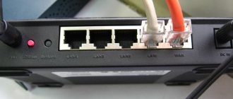
First of all, if you access the Internet through a router installed at home, you should check its functionality, namely:
When using Wi-Fi, you need to check the operation of your device's wireless network adapter by connecting to another computer or mobile phone's access point. If you use a special utility from your provider to connect to the Internet, you will need to reinstall it to check.
In cases where there is a connection, but there is no Internet, you will most likely have to contact the technical support service of the service provider, since this situation often arises when the cable is broken, the provider’s network equipment malfunctions, or access to the global network is blocked due to late payment.
Expert opinion
It-Technology, Electrical power and electronics specialist
Ask questions to the “Specialist for modernization of energy generation systems”
How to Crimp Twisted Pair: Step by Step Guide - Lifehacker Nowadays, most routers have Gigabit Ethernet, so one step we can take is to enter the router configuration and check the speed at which it is connected. Ask, I'm in touch!
Insulation check
To test insulation with a megohmmeter or multimeter, the principle of continuity is the same as when searching for an electrical connection between the cable cores.
The testing algorithm is as follows:
- set the maximum range on the device - 2000 kOhm;
- connect the probes to the wires and see what the device display shows. Considering that the wires have a certain capacitance until it is charged, the readings may vary. After a few seconds, the device display can display the following values:
- one, this indicates that the insulation between the wires is normal;
- zero – there is a short circuit between the cores;
- some average readings, this can be caused either by a “leak” in the insulation or by electromagnetic interference. To determine the cause, switch the device to the maximum range of 200 kOhm. If the insulation is faulty, the display will display stable readings; if they change, then we can confidently talk about electromagnetic interference.
Attention!
Before checking the insulation of the electrical wiring, it must be de-energized. The second important point is that when taking measurements, do not touch the probes with your hands, this can introduce errors.
Video: Wire continuity check - integrity check.
Options for wire testing
In general, the term “continuity” of wires includes a wide range of issues, from checking their integrity to determining the insulation resistance of the wire. We are primarily interested in issues related to faults in the wiring of a house or apartment, so we will focus on them.
Checking the integrity of a single piece of wire
The most common problem is a broken wire. It can happen for a variety of reasons, ranging from outside interference to burnout. To determine this damage, you can use a multimeter, a tester, a two-pole voltage indicator with a circuit monitoring function (the most common model is “Contact”) and a single-pole indicator - a screwdriver.
- Let's start with the simplest case, when the wire that needs checking is lying on our table. Before testing a wire with a multimeter, you should turn it on and set the parameter being measured. We will measure the resistance. This value is usually denoted "Ω". If there is no such designation, then we look for values with units of measurement “Ohm” - resistance is measured in these units.
- When testing with a multimeter, you can select any measurement limit. But usually they choose within 100 Ohms. After this, we check the functionality of the multimeter by shorting its two ends. Ideally, it should show 0 Ohm, or a value very close to this.
- Now we take the wire that needs testing and touch the leads of the multimeter to its ends. Ideally, a value should appear as close to 1 Ohm as possible. If the wire has a break, a very large value or “-EL-” will appear.
Multimeter Controls
Note! When touching the leads of the multimeter to the ends of the wire, do not touch the contact part. This may negatively affect the measurement results.
After all, if a person’s insulation resistance is lower than that of the wire, it will show exactly that.
To measure the integrity of a wire with a tester or “Contact”, simply touch the ends of the cable. If a light bulb or diode lights up, this is a signal of wire integrity. Accordingly, if the light does not light, then there is a break. But there are times when it is necessary to determine the integrity of the wire, and only an indicator screwdriver is at hand. In this case, you can also check the integrity of the wire, but our instructions cannot recommend it, because it involves a certain risk
Therefore, it can only be used in extreme cases and very carefully.
Voltage indicator "Contact"
In this case, we determine the phase in the nearest outlet
We insert one end of the wire into the phase terminal of the socket, and at the other, taking all precautions, we check for the presence of voltage. If the wire is intact, then the voltage will be
Determining wire integrity in hidden wiring
But unfortunately, it is not always possible to get easy access to both ends of the wire that needs to be checked. Often they are hidden under a layer of plaster and it is impossible to reach both ends with a multimeter, tester, or indicator. But don't despair! There are ways to test a wire with a tester or multimeter in this case too.
Note! Before drawing a conclusion about a broken phase wire, make sure that there are no switching devices in the circuit. On a car these could be fuses, but in an apartment they could be switches
The photo shows the simplest test of wire integrity
- With the neutral and protective wires, everything is a little more complicated. Since it is difficult to ring a wire with a tester due to the distance of its ends, you need to make sure that this is possible. First of all, we remove the voltage from all the wires located in the junction boxes in which work is to be done.
- Now, using a jumper or regular twist, we connect the wires that require testing. To ensure accurate readings and eliminate errors, it is better to disconnect them from other wires in the box. If there is no protective wire, then after checking that there is no voltage, we connect the neutral and protective wires.
- Now our wires have formed a single circuit. Therefore, in the area opposite to the connection point, we check the presence of a circuit between them. This is done in the same way as in the method described above with a separately located wire.
- You say okay, we know that there is a break, but in which of the two wires? It's simple. If you decide to check the network due to a breakdown, then the break is in the neutral wire. Since the protective wire only provides safety against electric shock and does not affect the performance. If you have a two-wire circuit and you checked by connecting the neutral wire to the phase wire, then we have already checked the integrity of the phase wire.
Finding the break point
After a break in the electrical wiring has been discovered, it is necessary to localize the place where it happened. For dialing in this case, you can use a tone generator, for example, the Cable Tracker MS6812R or TGP 42. Such devices allow you to determine the location of the break with centimeter accuracy, as well as determine the route of hidden wiring; in addition, the devices have other useful functions.
Devices of this type include an audio signal generator and a sensor attached to an earphone or speaker. When the sensor approaches the place where the UTP cable pairs or electrical wiring wires are broken, the tone of the sound signal changes. When a tone test is performed, the wiring must be de-energized before connecting the sound generator, otherwise the device will be damaged.
Note that with the help of this device you can test both power and low-current cables, for example, check the integrity of twisted pair cables, radio wiring or communication lines. Unfortunately, such devices will not allow you to determine the correct connection; special equipment is used for this purpose - cable testers.
Simple cable testers with additional features
Such devices are a further development of the testers described above, and perform a similar basic function, but with a number of nuances. For example, the tester kit may include a set of identifiers to match the sockets and sockets of the patch panel. Just the kind that are made by the system administrator himself when testing the cable with a multimeter. In the factory version, such identifiers are as convenient as possible and the transmitting module of the tester has an indication for their entire number at once. By connecting the indicators to the sockets of the patch panel and walking with the tester itself through unknown sockets, you can immediately see where the cable route from each of them ends and whether it is in good condition. A useful feature that significantly reduces network layout time.
Also, such testers may have an additional generator (for supplying an analog signal to the line) complete with an inductive probe - an analogue of the old method of cable technicians with a nine-volt battery to search for pairs by “unpairing” the wires. The probe has a light and sound indication when it approaches a core with a signal from the transmitter.
The disadvantage of this method is the strong susceptibility of the probe to extraneous electrical influences, both low-current and from a 220V network.
To avoid interference, it makes sense to use test sets with a digital signal or equipped with a probe with a 50 Hz filter. Such generators are convenient to use where power lines pass nearby or where fluorescent lamps are installed. Sets with a digital signal can be used even on lines that contain active Ethernet (without disconnecting from the patch panel).
Homemade contactless dialing
Below is a diagram of a simple non-contact break detector; it can be assembled within one evening. Considering the small number of parts, you don’t have to bother making a printed circuit board, but use wall mounting.
List of required radio components:
- variable resistance R1 – 100 kOhm;
- resistor R2 – from 4 to 8 MOhm;
- electrolytic type capacitors: C1 and C3 – 220 µF, C2 – 33 µF;
- ceramic capacitor with a capacity of 0.1 μF;
- D1 – LAG 665 chip (preferably in a DIP package);
- SP is a regular earphone from a telephone headset.
The circuit can be powered from a source with a voltage of 2 to 5 volts.
The dipstick (P) is made on the basis of a regular spoke from a bicycle wheel.
Properly assembled contactless cable testing does not require adjustment.
Video: Do-it-yourself cable testing. How to test wires using a light bulb and battery
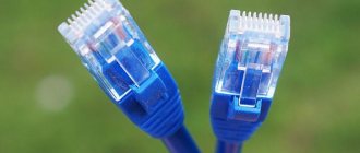
For testing telephone cables and twisted pair patch cords.
This device was taken to test specifically twisted pair patch cords on RJ-45
.
It often happens that during work a wire gets bent somewhere, and some core simply breaks off and stops working. Thanks to this tester, you can easily find which jelly is the problem, and if necessary, re-crimp the entire wire, for example into 4 wires. It is known that patch cords crimped onto 4 wires support a speed of 100MB
, which is quite suitable for the Internet. This is very important if the wire is quite long, it is not clear where the break is, and there is simply no way to buy a new one.
Of course, there are professional testers that show in which wire and at what distance there is a break, and measure the length of the wire itself, but this equipment will be relevant for professionals, but such a device is enough for me.
To check, I will use two patch cords, one straight and one cross. Direct twisted pair crimping is used to connect a computer to a modem, router, switch and any other network equipment. This crimp is universal and supports gigabit speed when using 8 wires, or 100Mb when using 4 wires. It is very easy to crimp, the wires correspond to each other, that is, 1=1, 2=2, etc. The image shows more detail.
For the test, I have a wire with a direct crimp, I will crimp another, the so-called cross crimp. This type of patch cord is used to connect computers together without using network switches. The procedure for crimping the wires can be seen in the image below.
For crimping we will need: a crimping tool, two RJ45
and a piece of twisted pair.
We align the wires according to the picture for cross crimping, cut off the uneven edges and insert them into the plug.
We insert the wire so that the ends of the wires are visible from the other end, then crimp the wire itself.
Plugged and crimped RJ45
In this sequence we make the second end
Now about the tester itself.
The tester is supplied in a protective case, which is very convenient during operation.
Power is supplied from a 9 volt element of the crown type. The tester itself consists of two parts, this is the main “setting part” with LEDs and an operating mode switch, and the response part, which shows which wire is currently ringing. The tester parts can be easily separated from each other.
The switch has 3 positions, this is OFF
(off),
ON
(normal operation),
S
(slow switching).
Checking straight cable.
We connect the cable to the connectors and turn on the tester. Lights 1 to 8 on both parts of the tester should light up alternately. If at some stage a light bulb does not light up, then there is a break in that jelly.
Checking the crossover cable.
The situation is more complicated when checking the crossover cable. Since the wires there are not sequential, the resulting light bulbs will light up in this order:
If we insert the wire in reverse, the sequence will reverse. In principle, if the light comes on, then there is already contact.
I was very pleased with the ability to work without using a response part. Instead, a network card for a computer or other network equipment can serve.
This means that if you connect one end to the network card, the other to the master part, the lights will light up alternately, indicating that the patch cord is working, or vice versa, that it is broken. By the way, I also found RJ45 plugs on Aliexpress:
This article will discuss mistakes that can be made when installing RJ45 connectors and types of damage to the twisted pair cable used in data transmission cable systems. The drawings are provided as examples of malfunctions and do not serve as examples of the correct crimping pattern.
Split pairs:
What is a split pair?
A split pair is a serious installation error in which wires from two different pairs are mistakenly combined into a “working” pair (the wires are not twisted together). This fault occurs when the installer confuses the same color sequence of wires in the connector at both ends of the cable. Data transmission, as before, will be carried out over two conductors, but they will no longer be twisted together.
Why is it necessary to twist wires in pairs?
In telecommunications, data is transmitted over wires twisted together—called “twisted pairs.” The conductors are twisted to minimize mutual interference and reduce electromagnetic interference. Several twisted pairs in turn form a cable. Pairs even have different pitches of this twist so as to have less impact on each other. A split pair results in problems such as line crosstalk, excessive signal propagation delay between pairs, video interference, bit errors, or data loss.
Will a simple cable tester see a split pair?
Simple cable testers typically test conductors for continuity, electrical integrity, resistance, and capacitance, but do not test for crosstalk typically associated with separated pairs. Accordingly, by checking the cable with a budget twisted pair tester, you will get a good result if the line is installed incorrectly. This is because the test will be carried out only for the possibility of current flow, and since this possibility exists and the wire numbers at both ends of the cable match, the fault will not be detected. To detect split pairs you need to use a good professional cable tester. The cable length must be at least 50 cm; on shorter patch cords, it is almost impossible to detect this damage with test equipment; only visual inspection of the color scheme of the wires will help.
You can detect a split pair using Softing cable testers:
Open pair:
| Example of pair break_1 | Example of pair break_2 |
A broken pair, or simply a lack of contact in a UTP, STP, FTP cable is a simple, common damage. It can be detected by any cable tester that works in tandem with a remote identifier. The device will supply a signal (current) to each conductor, and the response part will receive it. If a signal is not received from the main device, then there is no integrity of the wire. The principle of the simplest “dialing” works here. Of course, it is worth mentioning the limitations of the measuring equipment itself, which is designed for a certain maximum cable length, usually at least 305 meters, so that an entire coil of cable can be tested. The distance to a pair break can be measured by testers that can determine the line length by capacitance or by time domain reflectometry (TDR).
Break of one conductor (Miss wire):
| Example of a broken wire_1 | Example of one wire break_2 |
A broken conductor is also an easily identifiable fault. The detection methods are similar to pair breakage. It is worth noting that testers can recognize the absence of one contact as a break in the entire pair, however, this is not too important, since the line will still have to be repaired.
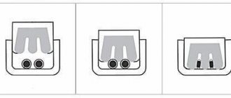
Reversed pair:
| Inverted pair example_1 |
|
An inverted pair is an installation error of a modular connector or socket (for example RJ45). May also be called inverse or reverse. Occurs when the wires of one pair are attached to the correct contacts at one end of the cable, but are facing down at the other end. The core, which at the beginning of the line had serial No. 3 (Fig. Example of an inverted pair_1), at the end of the cable is crimped onto contact No. 6, and No. 6, in turn, comes to contact No. 3. This damage can be detected by any tester, but it can only be localized by visually inspecting the connector.
Crossed wires:
| Example of crossed wires_1 | Example of crossed wires_2 |
The “crossed wires” twisted pair installation error occurs when the installer, having crimped the connector correctly on one side of the cable, swapped wires from different pairs on the other end. The problem is easily identified even by simple testers. This can be solved by repeated, more careful crimping of the connector in compliance with the correct crimping pattern.
Sometimes it happens that your home Internet connection disappears on your computer. This is not always due to non-payment of services, viruses or problems with the router. There are times when the Internet cable is physically damaged. Most often, its role is played by a twisted pair cable. This material will discuss in detail how to check the Internet cable for integrity.
If at a certain moment a notification appears on the screen of your personal computer that there is no cable Internet or it has stopped working, but it is paid for and there are no problems with the router, then most likely a problem has arisen such as a violation of the integrity of the Internet cable.
First of all, you need to reconnect the router to the network. To do this, remove the power plug, wait a couple of tens of seconds, and the router is turned on again. If there is still no access to the network, the quality of the connection has nothing to do with it and the reason lies elsewhere. Most likely, the problems lie in the network card or a damaged cable. If the connection suddenly disappears without user intervention, this may be due to:
- Viruses that have entered the PC;
- Installing and launching unverified games and applications;
- Voltage surges.
Important!
Finding out this in Windows is quite simple. You need to go to the “Control Panel” and go to the “Network Connections” item. Here you can find out whether there is a network connection or not. You can also diagnose your PC to ensure the network card is working correctly and update drivers.
The functionality of the card can be checked using the following steps. You need to go to the “Start” menu and find “Control Panel”, and in it “Device Manager”. The latter can also be found through Start. In the manager you need to find the section with network cards. If an alarm icon appears next to the selected board, then this is the problem. The cause of its malfunction may be thunderstorms and lightning. To check the card, you can move it to another computer with preliminary installation of drivers, provided that the computer is working.
All this may not help. Then it is recommended to call your provider's hotline. Perhaps the problem with the lack of Internet is due to failures on its side. If this does not solve the connection problem, then most likely there is a problem with the Internet cable. Among them:
- Broken wires;
- Short circuit of individual cores;
- Complete break.
Important!
The cable may be located on the floor and break at the junction of the walls. One way or another, in these cases the Internet cable needs to be repaired. You can check the cable for signs of faults without specialists, using various methods.
Fault Analysis
We will start from the losses received when sending packets. It is important to understand that the ping command is a protocol of the fourth level according to the nesting of the OSI model, that is, software, network and hardware errors are excluded, but data levels 5-7 according to the OSI model are not checked.
It turns out that a cable break, if present, can be identified in this way and is the easiest to do. But the programs do not allow you to identify the specific location of the cable failure, but only indicate the area.
How to check an Internet cable or local cable and understand that there is a break? Eliminate other options related to a faulty network card or router. If there were packet losses when scanning the computer itself:
- Restart your network connection.
- Disconnect from all network add-ons (VPN, proxy).
- Do a Network Reset.
- Update or reinstall the network card driver.
If packets are lost in the PC-router section:
- Reboot your router.
- Check that the Ethernet cable connectors are securely seated in the port of the router and the network card (motherboard).
- Switch the Ethernet cable to the next port on the router.
- Restore the router to factory settings.
Check the connected port indication on the router. If it doesn’t light up, there are two possibilities: the capacitors on the router board have malfunctioned (or another hardware failure of the router) or the cable is faulty.
If packets are lost when accessing the Internet:
- Reboot your router.
- Free up a dynamic IP address in your router settings.
- Turn off VPN and proxies.
- Ping other remote servers to ensure that the server is not accessible.
- Load Internet pages through another browser.
- Restore your router to factory settings.
- Call your provider to find out the cause of the problem.
If packets are still not being passed through, there are three possible reasons: a faulty Internet cable, a problem with DNS processing, or problems with the provider’s equipment.
Using verification software
Users often start searching for software online, but do not realize that they already have these programs as standard on their PC. This is not only a diagnosis of network errors, but also a program responsible for the Internet icon. If she detects its absence, then the picture changes to the appropriate one. This symbolizes problems associated with a broken or shorted twisted pair cable.
No program will show you exactly where the cable is damaged, but there are solutions that have more functionality than standard ones.
An example is a good software solution called Network Traffic Monitor. It is completely free and has wide functionality, including:
- Measuring network speed in case of problems and instabilities;
- Analysis of network speed changes;
- Saving all reports on your hard drive;
- Making deep settings;
- Possibility of using useful services;
- Many languages supported.
Installing the software doesn't take even a minute. All you need to do is run the EXE file and agree to the installation. After this, the program will install and be ready to use. Network Traffic Monitor is considered one of the best testing and diagnostic programs. This is evidenced by numerous user reviews.
Prepare everything you need
It is advisable to take extra plugs in case it doesn’t work out the first time. The crimping itself is performed with a special tool - a crimper. But for one-time use there is no point in buying it. After all, you can easily get by with improvised means, such as a flat-head screwdriver or a knife.
Cut a piece of twisted pair cable to the required length and carefully remove 2-3 cm of outer insulation from both ends. It must not be cut all the way through so as not to damage the wires. To do this, take the scissors, squeeze them slightly and twist them around the axis of the cable. Then simply remove the cut shell with your hands.
Do not strip too much: if the insulation does not go inside the connector, it will not fit well on the cable and the contact may break over time.
Slow cable Internet: causes and solutions | ITIGIC
The driver may be missing for some reason. Then specialized utilities, for example, Driver Genius, will come in handy. Download it from the developers site, and then update all outdated drivers. The utility database is regularly updated, so it is always up to date.
Expert opinion
It-Technology, Electrical power and electronics specialist
Ask questions to the “Specialist for modernization of energy generation systems”
The network cable is not connected. What to do if it is connected but not working Nowadays, most of the routers have Gigabit Ethernet, so one step we can take is to enter the router configuration and check the speed at which it is connected. Ask, I'm in touch!
About connecting a PC to an active network using twisted pair cable
To carry out a quality check of the Internet cable, you need to understand the elementary circuit of connecting a twisted pair of a personal computer to another device. You can see the diagram in the picture below.
Of greatest interest is the diagram showing the diagram of the card or hub to which the PC is connected. Most often it is connected via an RJ-45 connector. Each twisted pair is connected to the transformer symmetrically. This may mean that the transformer has a winding and its middle. Inside it there is a tap, which, in turn, is connected to a common conductor using a resistor and capacitor. This ensures that there is no interference in the cable and a clear, unchanging signal. Another advantage of such a transformer is the protection of cables from tangling and short circuiting.
What types of internet sockets are there?
Internet socket rj 45 can be found in two different versions:
- Outdoor. This type of socket is installed on the wall. These sockets are used when the network cable runs along the wall.
- Internal. These sockets are installed in the wall. If your twisted pair wire is hidden in the wall, then for convenience and beauty use an internal socket.
Both options can be easily disassembled into several parts. One half of the case performs a protective function, the second half is designed for mounting on or into a wall. There is also an internal part, it is needed to connect the socket to the wire. It is equipped with thin contacts, with their help, with a slight pressure, the insulation of the twisted pair is cut and a reliable contact appears.
You can find single and double RG-45 sockets on sale. Internet sockets, depending on the manufacturer, will differ visually and in quality, but functionally they are all the same.
About the swing strength and waveform of twisted pair
The first thing to do is an oscillogram of the information signal. After analyzing it, we can conclude:
- The presence in the network of Rx and Tx type signals of the same shape and a swing of 2 Volts;
- That one pair transmits a signal and the other receives it;
- The fact is that if any one falls out of the connector, the signal will stop transmitting;
- The signal shape is round;
- The signal has distance restrictions between its various points, which does not exceed 100 meters.
Important!
A two-volt swing does not pose a risk to human health or equipment operation. You can check a twisted pair cable without disconnecting from the network or turning off the equipment in the same way as a telephone cable.
Features of RJ-45 cable pinout
Before connecting Internet sockets, you need to clearly know and understand where and what color to mount each individual twisted pair wire. To do this, you need to know the crimping scheme and the rules for crimping RJ-45 cables with your own hands.
There are two main types of RJ-45 wire pinouts: straight and crossed. The first type of cable is used to connect end devices (computer/PC, smart TV/Smart TV, switch/Switch) to the so-called router.
The second type of cable is used to connect devices with similar functions (computer - computer, router - router, switch - switch) to each other.
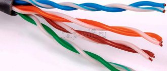
For a direct scheme, the color matches the color in this order: white-orange, orange, white-green, blue, white-blue, green, white-brown, brown. For the cross, everything is the same, but the green ones change places with the orange ones, respectively
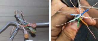
First, we leave about 100-150 mm from the plane of the wall along the length of the cable, and cut off the rest of the cable. This length will be sufficient for possible subsequent rewiring of the wiring.
Now you need to free 4 pairs of wires from the outer sheath and from the foil (it acts as protective shielding), if any.
Inside the twisted pair there is also a special thread with which you can easily release all the necessary wiring. You can also use a regular knife or a special cutting surface, which is equipped with almost all crimping pliers.
Crimping pliers will help you easily mount any RJ-45 and RJ-11 connector, the main thing to remember is that if the tool itself does not press the wires enough, then you can press it with a knife or a thin screwdriver
At the next stage, we straighten all twisted pairs of multi-colored wires and carefully “seat” each individual color into its niche according to the color pinout in the socket terminal block.
This must be done in such a way that the rest of the wire with “untouched” insulation falls under the fixing clamp of the terminal block. Now we tighten the fixing bolts with a screwdriver on the terminal block and at the same time press the remaining wires so that they do not come out of their seats.
Finally, with a “feeling of strength,” we recess the clamping connectors on the terminal block with a screwdriver and separately secure each core in the terminal group, while cutting through the braid of small wires. Then we cut off the remains. The wiring must all be located at the same height from the base of the terminal block.
You may also find information about ways to extend twisted pair cables useful.
How to check the break of an Internet cable and the integrity of its insulation at home
If all methods for determining the cause of the failure fail, then most likely the cable has suffered a break or short circuit. To find a problem area, it is not necessary to inspect the cable along its entire length, but if it is not large, then this can be done. If the twisted pair is not completely broken, it is impossible to find the break inside with your eyes. Instruments and folk remedies for detecting breaks and short circuits come to the rescue. These include professional testers, simple multimeters, and testing methods using salted water or potatoes.
Our ISP outages and software issues
If the Internet is slow over the cable, this may also be due to a failure of our Internet provider. If everything is going wrong and you have checked your hardware and software, there may be a specific glitch. Also, one way to check this could be to test on multiple computers.
- Make sure we don't have any viruses or malware. To do this, we will pass on antivirus and, if possible, anti-malware software such as Malwarebytes.
- We must update our operating system with the latest security patches.
- Clear our browser cache and try other DNS servers.
In short, cable Internet is slow due to hardware problems, software problems, saturation or failure of the Internet connection.
There is no Internet on the computer through the router. What to do if there is no Internet connection: expert advice
Users can change the MAC of the network card itself in two ways. The first includes the following steps:
Expert opinion
It-Technology, Electrical power and electronics specialist
Ask questions to the “Specialist for modernization of energy generation systems”
Connecting the Internet without a router - directly via cable and without it | Hardware setup Remember that without an antivirus installed, your computer will be absolutely defenseless against malware from the global web. Ask, I'm in touch!
Tester is an excellent way to check
Using a tester is the best way to find out if there are cable breaks. Before starting the test, you should inspect the cable along its entire length, and especially pay attention to the quality of the crimp on the plug. If the crimp is bad, there will be problems with the contact of some wires. They can also be overlapped in a fixed position. This way they won't close themselves off. If a breakdown cannot be detected at first glance, then you can use a tester that will provide a quality check.
Important!
Modern testers have great functionality and are easy to use thanks to their displays. They allow you to ring the cable and accurately determine the location of the break and short circuit. We can recommend the Tester MicroScanner Pro model.
This is one of the most popular devices on the market because it has many features, including:
- determining the degree of correctness of the wiring;
- determining the location of the breakdown;
- determination of the type of failure;
- determining the distance to the breakdown site;
- wire tracing product.
Such a device is good, but only if you have a multimeter or a regular pointer tester at hand. They will help you measure the resistance in the circuit, voltage and type of current. A multimeter may well be enough to analyze a twisted pair cable. To start the analysis, you need to turn on the resistance mode and bring the ends of the cable to one point. If this happens, then further verification is carried out in the following order:
- checking the integrity of all cable cores separately;
- testing each cable by color;
- checking for short circuits with adjacent conductors;
It often happens that it is impossible to make ends meet. Then the connector is either cut, or the wires at one end are stripped and connected to each other. After this, the pairs at the other end are probed with a multimeter.
conclusions
Based on the real tasks performed by the average system administrator every day, we can say with confidence that the most common of them are:
- Check the correspondence between the socket and the patch panel socket.
- Checking the correct crimping of the RJ45 connectors on both ends of the patch cord.
- Checking the contact in sockets, checking the contact of crimped patch cords, checking each core in the twisted pair route from the socket to the switching cabinet for signal passage.
- Pulling cables to new workplaces with paneling, sockets and their marking.
The administrator usually solves other tasks using a laptop and many different utilities. An administrator can ping a server, workstation, or test the data transfer speed in his organization without the use of expensive equipment. Of course, it is optimal if it is available, but as a rule, the administrator’s main “weapon” is simple cable testers of low and medium price ranges, providing a quick solution to urgent problems.
High-price network analyzers are more suitable for more complex tasks, which require the appropriate qualifications of a network engineer to solve. Such tasks, as a rule, are of a deeper nature and are mainly focused on the high-quality operation of business applications and services, the downtime of which determines the financial losses of companies.
See professional tool kits on pronabor.ru.
Checking with a dial multimeter
This is almost the easiest way to ring a cable, since such a device is found in almost every home. To check, take green and orange pairs of veins. The procedure is as follows:
- switch the device to search for resistance;
- touch the orange veins with a chisel;
- the resistance should be set at several ohms;
- touch the green veins and carry out a similar check;
- touch the orange and green veins and get a resistance value of 100 Ohms and above.
If the measurement was successful and showed the same numbers, then this indicates the excellent condition of the wires. If pairs do not ring through, it is necessary to replace them with unused ones, for example, brown or blue.
Setting up and preparing the multimeter
To use the multimeter correctly, you need to configure it. This means that you need to select the value to be measured and the limit of its operation, that is, the value beyond which it will not go.
Symbols on the front panel of the meter
A multimeter can be used to check various electrical quantities: current, voltage, resistance, frequency. It is also used to test the performance of various radio elements: resistors, capacitors, diodes and transistors. The very part of the word “multiple” implies the presence of several types of measurements. To select these types, there is a knob on the front panel of the tester, by turning which you can select the required value.
In most cases, the symbols depicted on the body of the multimeter represent designations of electrical quantities accepted in physics or conventional graphic designations of radioelements intended for testing. On the front panel you can find the following symbols:
- U - voltage symbol;
- V - stands for volts, this is also a measure of voltage;
- I is the current; when you set the knob to this designation, the current strength will be measured;
- A - amperes, a measure of current strength;
- Ω, R - symbol of resistance;
- Ohm is a measure of resistance, Ohms;
- -| |- - this icon indicates a capacitor, the multimeter will measure its capacitance;
- Diodes and transistors are also marked on the tester body with their symbols.
But not only the measured values are indicated on the front panel of the tester: the holes for connecting the probes also have their own designations. One of the meter slots will always be occupied by the black probe. This is a common hole, it is usually marked with the inscription COM, which means “common”. In addition to it, the multimeter has two or three working holes, designed respectively for measuring voltage, low current and high current.
The socket marked U, Ω, Hz is intended for measuring resistance, voltage and frequency, as well as for testing various radio elements. You also need to install a probe here to test wires and cables for breaks.
https://youtube.com/watch?v=DU1hvRCR2Rw
The hole marked mA (mA) is used to test low currents (up to 1 ampere), and the hole marked A (10 A) is needed to measure high amperages.
Limits of measured values
In addition to designations of the values of the parameters being tested, designations of measurement limits are printed on the front panel of the multimeter. In more advanced equipment, these inscriptions are not present, since the tester electronics itself selects the limit based on the signal supplied to it at the input. However, most multimeters require manual adjustment of measurement limits.
Typically, limits are given by numbers that are multiples of 2: 2, 20, 200... Thus, when choosing a limit, you should be guided by the rule: choose a limit higher than the one being measured, but of the same order. For example, to measure the voltage in a home electrical network (in an outlet), you need to select the AC voltage measurement mode and the measurement limit of 2000 volts. And to test the wires with a multimeter, you need to select the resistance mode and the minimum measurement limit of 2 ohms. However, long cables require a higher measurement limit of 20 ohms. Additionally, you can turn on the button with a sound signal that sounds when a short circuit occurs (circuit presence).
Connecting the tester
To check the parameters of electrical circuits and the continuity of wires and cables with a multimeter, you must correctly connect the meter to the circuit being tested. When checking for circuit integrity, the required area between the meter leads is checked. Therefore, the tester is connected to the terminals of the circuit. If voltage is being measured, the multimeter must be connected in parallel to the section where the voltage is being tested.
When measuring current, the multimeter must be connected in series to the open circuit of the circuit being tested, for example, between the power supply terminal and the load terminal.
Checking in the absence of testers
A multimeter and tester may not be at hand. In this case, you can use the manual verification method. To do this, you need to cut off pieces up to 15 cm long from each end of the cable. Next, you should remove the winding by 5 cm. And expose the cores by a couple of cm.
After this, prepare a container with water, which should be made of glass or plastic. Ordinary table salt weighing 1/4 of the weight of water is added to the liquid and mixed until completely dissolved. The cable cores are conductors and their contact must be avoided.
The other side of the cable section must be connected to a power source with a voltage of more than 3 Volts. A regular battery, a smartphone battery, and other safe sources may also work.
After applying voltage, you should monitor the wires in the water. The negative conductor should be covered with white bubbles, and the positive conductor should be covered with yellowish-green ones. If everything is so, then the twisted pair is in good condition and no short circuit has occurred. If there was a short circuit, then bubbles will come from the other vein.
Possible problems and how to fix them
Now let's look at the most common problems.
Incorrect wire connection
If you have connected the wires incorrectly, then either your Internet will work too slowly (about 10 times slower than it should) or will not work at all. Incorrect connection of wires can be corrected only by dismantling the socket:
- Remove the decorative and front panels, pull out the terminal block.
- Open the cover and carefully check that the wires are in their proper places. It is very easy to confuse the connection according to marking A with marking B and connect half of the cores according to one standard, and half according to another.
- Correct the connection if necessary.
The wires were cut before the latch closed
If, after thinking about it, you accidentally cut off the wires before you pressed them with the clamp, that’s okay. You need:
- Remove the wires from the socket.
- Strip the cable a couple of centimeters higher.
- Redistribute the cores as required.
- Close the cover/lock.
- Cut off excess pieces of wire.
Sources
- https://Vpautinu.com/internet/rozetka
- https://lanportal.ru/lan/kak-podklyuchit-internet-rozetku.html
- https://FishkiElektrika.ru/kak-podklyuchit-internet-rozetku-k-vitoy-pare-instruktsii-i-shemy
- https://help-wifi.com/poleznoe-i-interesnoe/montazh-kompyuternoj-setevoj-rozetki-rj-45-svoimi-rukami/
- https://kak-sdelano.ru/elektrica/kak-podklyuchit-internet-rozetku
- https://itmaster.guru/nastrojka-interneta/internet-na-pk/kak-podklyuchit-internet-rozetku.html
- https://stroychik.ru/elektrika/podklyuchenie-internet-rozetki-rj-45
- https://camodelkin.ru/izolyaciya/kak-podklyuchit-internet-rozetku.html