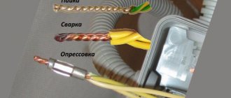
Fiber-optic communication lines have a high information signal throughput. Their work largely depends on the quality of the wire connection: the better the hairs are connected, the lower the degree of signal attenuation at the point of contact. Multilayer wire has a complex structure; special equipment is used to weld the joints. It's quite easy to work with.
Splicing fiber optics does not require special skills or training. Just follow the instructions. Before doing this, it will be useful to know some of the nuances of the work. When installing communication lines, a lot of time is spent preparing the cable for the welding process; there is special equipment for this.
FOCL welding technology
The length of the optical fiber is measured, it is produced in coils. Multi-kilometer long fiber-optic transmission lines are created by two types of connections:
- detachable;
- one-piece.
Detachable ones require additional costs; connectors and adapters significantly reduce the light transmission of the signal. More often, permanent connections are made by welding fibers with special devices.
Necessary tool
High-quality installation of fiber-optic lines is impossible without two devices:
- cleaver, an apparatus for optical fiber, allows you to cut the cleaned cable strictly at a right angle;
- reflectometer or tester, it determines the accuracy of the connection.
Tools are needed to strip the insulating sheath. A standard soldering kit will do the job. There is everything there: wire cutters, pliers, solvent or alcohol, special thick wipes for removing the waterproof layer. The reliability of the connection depends on the quality of surface cleaning.
Fiber optic cable tool
Preparatory work
The process of preparing the cable before refilling takes a lot of time. First, the optics are examined. Water destroys the light-conducting layer. If the end of the wire is wet, cut off at least a meter from it with a wire cutter. To remove the sheath, the cable is stripped down to a hydrophobic gel. Cutting with a stripper knife does not take much time: after a circular cut at a distance of at least 3 cm from the end, it is enough to pull the cable together. The waterproof layer is removed with a solvent and lint-free wipes. It is necessary to remove the insulation completely, this affects the quality of the chip.
Connection process
The cleaver produces a high-precision perpendicular cut. After this, the welding process begins. Main stages of work:
- the ends of the wire are placed in the device towards each other and fixed;
- the device adjusts the conductor and brings the ends together;
- then an electric discharge is passed through, dust particles are destroyed in the arc zone;
- the fibers are soldered together under the action of an arc, the silicon melts, and a diffuse connection is formed;
- after welding, the connection is tested: the device moves the soldered ends apart with a certain force;
- A heat-shrinkable tube is placed over the connection; in the oven, it forms a protective sheath on the wire;
- When the device completes the second part of the work, the timer gives a sound or light signal.
Cleaver and reflectometer
A cleaver is a high-precision mechanical device that provides a perpendicular cut of an optical fiber. The quality of the weld depends on the quality of the chip.
If the cleavage is bad, smart welding machines simply do not weld the optical fibers. Among cleavers, Japanese ones are also the best.
Some experts attach such great importance to it that, if there is a shortage of funds, they prefer to purchase a high-quality Japanese cleaver, and in addition to it they buy a relatively cheap Chinese welding machine.
Immediately after chopping the optical fiber, it is necessary to insert it into the welding machine and begin welding; there should be no intermediate actions, otherwise this will lead to contamination and poor welding quality.
The third device that you can’t do without is a reflectometer; it measures the quality of the line; its readings determine whether the fiber-optic splicing needs to be reworked or not.
A combination of precision welding equipment combined with operator experience will produce a reliable connection with optimal signal transmission characteristics.
Cable structure
The signal is transmitted through a thin silicon dioxide glass filament, the size of the conductor is calculated in microns. The cable can contain up to 38 cores, all of them are insulated. Silicon glass is a very fragile material and is susceptible to moisture, so it is covered with multilayer insulation. First, they are coated with a protective varnish, then placed in modular tubes filled with water-repellent gel, which protects the glass conductor from swelling. The tubes are additionally covered with flexible insulation, then with a layer of polyethylene.
Structure of a fiber optic cable
Insulation depends on the operating conditions of the cable. It is divided by type:
- external cable can be suspended or underground;
- internal for laying is rarely used; it can be found in business centers.
Overhead cables are used to make overhead communication lines; sometimes the cable is additionally equipped with a cable and clip holders. Some manufacturers produce underground ones for laying in the ground in corrugated armor.
FOCL welding procedure
FOCL - fiber-optic communication lines. Their welding is carried out in stages:
- The fiber optic cable is divided: the insulating coating is removed, individual modules consisting of a certain amount of optical fiber are separated. They are welded separately.
- The fibers are cleaned (the moisture-proof coating is removed from them).
- KDZS is put on the optical fiber - a special attachment made of heat-shrinkable tubes and reinforcing rods.
- The protective layer (gel, varnish) is removed from the fiber ends and treated with alcohol.
- Then the fibers are fixed with precision cleavers (the cleavage should form perpendicular to the fiber axis).
- The fibers to be welded are placed in V-shaped grooves (clamp).
- They are combined under a microscope. In modern models, this procedure is performed automatically.
- The fibers are heated by an electric welding arc to the required temperature.
- By means of mechanical deformation, the welding of the fiber optic cable is tested for strength, and the attenuation process carried out by the joints is evaluated.
- The welding equipment operator installs a protective kit on the welding area of the product, which is then placed in a special thermal chamber for temperature shrinkage.
Optical fiber welding parameters:
| Types of fibers welded | Single quartz optical fibers:
|
| Spliced fiber diameter | 80 µm - 150 µm |
| Spliced fiber coating diameter | 100 µm - 1000 µm |
| Stripped fiber length |
|
| Average losses per welded joint |
|
| Reflection coefficient from the welded joint, dB | No more than 60 |
| Types of Heat Shrink Tubing Used | Standard, 60 mm or 40 mm long, as well as smaller sizes |
From us you can also purchase everything you need for optical communication lines (cable, couplings, cross-connects, connectors, cords), as well as equipment for installing and testing optical lines, including professional reflectometers from Fluke Networks.
Optical line repair
FOCL repair consists of the following steps:
- finding the location of the optical line break;
- organizing repairman access to damaged optical fibers;
- optical cable repair;
- re-checking the cable route.
As stated earlier, the break point is looked for using a reflectometer. Signal loss can occur either in one of the cross-connects or couplings, or in the middle of an entire cable section (for example, underground work at the cable laying site).
fiber-optic connection coupling
In the first case, the place of the poor-quality seam is broken and a new welding of the optics is done. In the second case, everything is much more complicated; repairing the optical fiber is impossible. If technical reserves and the particular location of the cable allow it, then an additional coupling is installed at the break point. Otherwise, the entire cable section is changed, welding work is carried out at both ends of the new cable. Repairing fiber-optic communication lines is a very expensive process, so it is better to carry out high-quality installation work in advance.
Fiber optic cable: types and composition
Before looking at the cable welding instructions, let’s look at what an optical cable is. FOCL are fiber-optic communication lines that are divided into categories.
- Design features: can consist of a shell with pipe modules or a multi-layer connection and two-level protection.
- Place of application: external or internal. Considering the high cost of optical cable, internal laying of a fiber-optic communication line is used extremely rarely, only in cases where high-speed, integral and accurate data transmission is necessary.
- Cable laying conditions: overhead, ground, sewer, underwater, suspended from power poles. The most commonly used cables are overhead, underground and sewer cables. Patch cords with cables and corrugated armor are less commonly used.
Recommendations for choosing methods for installing optical connectors
All the solutions described in the article have the right to life. However, as stated above, each of them has its own advantages and disadvantages that determine their use.
Thus, at the moment, adhesive connectors are practically no longer installed by users on their own due to the complexity of the technology and the low quality of the result. Basically, they are installed by manufacturers of patch cords and pigtails. At the same time, these companies have polishing machines, which increases the speed of installation. And the quality of polishing will be noticeably better than doing it manually.
Fast Connectors - recommended for use as a temporary solution during repair and restoration work, if there is no welding machine at hand, or if it is impossible to use it. Such connectors must subsequently be replaced with more reliable and durable solutions.
Terminating optical fiber using pigtails is the most common method. Pigtails provide excellent optical performance and reliability. They are justified in using when installing large optical cross-connects installed in the operator/provider premises. But for installation in street distribution boxes and for terminating fiber-optic lines in the subscriber’s premises, pigtails are not very suitable due to poor resistance to mechanical loads and dimensions.
Splice On connectors are still inferior to pigtails in popularity.
However, even despite the higher cost, their use is already justified for the installation of outdoor distribution boxes and cable termination at the subscriber premises when deploying FTTx and PON. This is due to excellent optical characteristics, protection from mechanical damage and climatic influences, durability, as well as simplicity and fairly high speed of installation. Most likely, with a decrease in cost and an increase in consumption, this technology can completely displace all others. And at the same time, all manufacturers of patch cords, because with a welding machine, Splice On connectors and a patch cord cable, any user can produce a high-quality patch cord in a few minutes. See also:
Searching for armored and unarmored optical cable underground: how to avoid mistakes
Certification and diagnostics of fiber optic lines: a complete guide!
How to choose passive optical components?
TOP 5 best splicing models for fiber optics
Device for splicing fiber optics.
Let us describe the most attractive machines for splicing fiber optic material in terms of functionality, quality of welds and cost:
- The Fujikura 80S fiber optic splicing machine is fully automatic. It has built-in video instructions and a Russian-language menu, which greatly simplifies the process of mastering its capabilities. The unit is capable of aligning optical fibers along the core, has automatic arc power adjustment, and is reliably isolated from moisture, dust, and mechanical damage. It features the highest possible welding speed and supports all types of networks. Approximate cost – 425 thousand rubles.
- Jilong KL-280G is an economical machine that features fast welding - 9 seconds. The optimal welding program is selected automatically, after which the device independently controls the quality of the created joint. It has a 5.5” liquid crystal display, capable of determining and displaying the fiber chopping angle, as well as its core. Cost – 355 thousand rubles.
- The Furukawa S177A automatic unit has proven itself to be one of the most compact and lightweight devices capable of center-aligning fiber optics. The welding machine is equipped with a bright liquid crystal display, a built-in battery, and welds all types of fiber optic cables with high precision. Price 690 – thousand rubles.
- Inno Instrument IFS-15S is particularly compact and aligns optical fibers in the middle. The unit is equipped with universal replaceable holders and a 4.3” display. Cost – 400 thousand rubles.
- DVP 730 operates with all types of networks, the device is equipped with a Russian interface, and is capable of operating from built-in power supplies for a long time. The device must be configured manually, and calibration and testing of the ends is carried out automatically. Price – 150 thousand rubles.
Cable cutting and cleaning
A stripper knife is used to remove the outer shell. It has rotating blades that can be used to cut off the outer layer. If the cable is self-supporting, then the cable is removed with cable cutters.
The inner shell should be removed with a specially adjusted stripper knife.
Threads, film, hydrophobe and other elements are removed from the modules. D-Gel solvent is used to remove the hydrophobe. You need to wear gloves when working; the gel is difficult to remove from your hands. Then the modules are wiped with disposable lint-free wipes with solvent, then with alcohol.
At the required distance, the modules are cut with a stripper and removed, leaving the fibers bare. Fiber failure often occurs at this stage.
The welder must work with extreme caution
The length of the optical fiber without sheaths is usually 1.5-2 m; this is required by the instructions for installing the couplings; welding and installation make the work easier.
Fibers must be handled with care. Any damage at any stage of the work leads to the fact that everything has to be done all over again. Before welding, the optical fibers are wiped with 3-4 dry wipes, then a new wipe is moistened in alcohol and wiped clean.
A heat-shrinkable tube is put on the cable for subsequent sealing of the entry into the coupling. When the cable is welded and laid in the coupling, the tube is shrinked using a torch.
The cable is inserted into the coupling, secured, and you can begin measuring the required length of the optical fiber and stripping it. Then a KDZS heat-shrinkable tube is put on it, which will further protect the welding site.
The bare, cleaned end of the optical fiber is inserted into the cleaver. The device cuts the fiber so that the end should be at an angle of 90 ° to the central axis. The permissible error is no more than 1.5 °.
Preparation for the process
The performance of fiber optic lines largely depends on the quality of the fiber connection. FOCL welding requires preparatory work, which, in particular, includes cutting the cable. The optical cable welding process itself requires cleanliness, so before starting it is necessary to ensure that there is no dirt and dust. The modules are removed using a stripper.
With its help, it is easy to get rid of the insulation of wires so that you can weld optical fibers. In addition to the welding machine, you must leave a cleaver on the workbench. This device is designed to ensure the ends of optical fibers are flat and perpendicular.
The device provides an even chip, which will guarantee the quality of welding of the fiber optic cable.
The procedure for using the cleaver is as follows:
- strip the fiber from the varnish covering it;
- remove dirt using a cloth soaked in alcohol;
- place the fiber in the groove of the device, focusing on the ruler;
- put the cleaver into action;
- remove the fiber from the device without touching its end.
In addition to the cleaver, it is necessary to prepare a reflectometer, with which you can check the quality of the resulting connection.
Cable cutting
Equipment for welding fiber-optic lines
The fiber optic cable is cut using the following tools:
Equipment for welding fiber-optic lines
- stripper;
- rope bite;
- screwdrivers;
- side cutters;
- a bottle of alcohol;
- lint-free wipes;
- insulating tape;
- numbers-markers on a self-adhesive basis and others.
If the fiber optic cable was stored in a damp warehouse, approximately a meter of cable should be cut off and discarded. If there is a cable, it must be cut with a cable cutter.
The outer sheath of the cable is removed using a stripper. This knife has a blade that rotates in all directions and can be adjusted according to the thickness of the cable. Using a stripper, a cut is made in a circle on the sheath, then two longitudinal cuts are made along the cable so that the outer covering breaks into two parts.
Removing the outer shell using a stripper
If the next layer is a Kevlar coating, then it is cut with a cable cutter. The metal corrugation is removed using a reinforced knife. The last thin shell is removed with a stripper.
Opened modules are treated with napkins using alcohol. To remove the hydrophobe, use a solvent. The module itself is bitten and removed using a special stripper. All that remains is to make sure that all the optical fibers are not broken.
Optical cable classification
Optical cables can be classified:
By structure:
- standard cables having a sheath with modular tubes;
- modern multilayer cables, which are endowed with two-level protection and other advantages.
By area of application:
- for outdoor use;
- for internal routing (this option is rarely used exclusively in data centers).
According to operating conditions:
- hanging;
- ground;
- for cable sewer systems;
- underwater;
- for power lines.
The most popular are overhead, ground cables, thin, paired patch cords. Cables with corrugated armor and cables are used a little less frequently. Other types of fiber optic cables are rare.
Tools used
As with soldering fiber optics, cutting a cable requires a special set of tools.
The standard set of tools for an assembler-soldier includes:
- set of strippers;
- screwdriver set;
- pliers;
- rope bites;
- set of knives;
- other additional tools for various work situations.
Today there are many tool sets from different manufacturers, with different configurations. They can be fully equipped with the necessary tools or contain only basic ones. Many manufacturers do not pay much attention to the strength of tool storage cases, but only to their appearance. They are made of fiberboard and covered with textured foil. Accordingly, such cases do not withstand long operating conditions under difficult operating conditions and require periodic repairs.
And some of the tools from the set may also be of poor quality, and some may not be needed at all. Expensive, high-quality branded consumables can be replaced with cheaper products.
Optical fiber connection methods
The fiber optic industry does not stand still: optical fiber splicing is constantly being improved, the methods of its implementation and the consumables used are changing.
Selecting the optimal fiber connection technology for each specific case is important from the point of view of reducing financial costs and increasing productivity.
Inexperienced welders do not always know exactly what needs to be taken into account when working with this material
When choosing a fiber splicing technology, it is important to consider the following aspects:
When choosing a fiber splicing technology, it is important to consider the following aspects:
- optimal speed of operations;
- the time period required to prepare the optical fiber for welding;
- amount of time for welding cables;
- cost of work;
- experience of specialists.
When laying fiber optic fabric, there is always a need to weld the optical cable into a single line.
Coupling for connecting fiber optics.
Today, the most common ways to perform this operation are:
- using mechanical connectors;
- directly on the optical cross-country;
- welding of optical fibers using special equipment.
The first method is used extremely rarely, because the gel in mechanical connectors dries out over time, which worsens the parameters of cable joints. The second is quick and easy to make, but the best fiber optic cable connections are made by welding.
This technology is characterized by the best indicators in terms of quality, durability, and reliability of the created connections.
First, you will need to cut an optical cable of 6-8 fibers connected in a module and covered with insulating material. The insulation is removed and the fibers are cleaned using special alcohol-based products.
After this, the fibers are placed in a welding machine for subsequent automatic welding
It is important to control the strength of the seams formed at the junctions of optical fibers. The welded elements will need to be placed in an optical coupling or cross cassette
On a note! The simplicity of this technology allows it to be performed even by an inexperienced welder who has personally observed this process being performed by a specialist. But the main thing is to have a special welding machine: conventional models will not cope with this task.
Production of welding works
For this, a special welding machine is used. The procedure for performing the fiber connection operation is approximately the same for all types of machines:
- After switching on, the clamp cover opens, the prepared 16 mm conductor is laid along the installed limiters, with a gap of 1-1.5 mm. to the junction. This operation requires visual control;
- Close the lid and press the start button. The connection process occurs automatically with the process displayed on the monitor screen.
- At the end of the connection, signal losses at the junction are automatically determined; a decrease in the level by 0.022 dc (Decibel) is considered a good result.
Then the KDZS protective tube is placed over the joint. To heat the heat-shrinkable tube, the welding device has a special compartment - a heat stove, where the “raw” insulation is placed. After warming up (about 40 seconds), the device gives a ready signal - you can take out the finished cable sheet. The process of joining fiberglass is clearly shown in the video.
Difficulties in splicing fiber optics
A fiber optic network, according to modern experts, is the best medium for high-speed transmission of various types of information. The material used to create such an environment is lightweight and low susceptibility to interference and radiation.
It is not capable of causing any obstacles to the path of information from one point to another, and due to its low power it is characterized by absolute electrical safety.
Since fiber optic materials provide soldered connections with high functionality and impressive efficiency, their scope of application is growing every day.
Today, optical communication lines are widely used to transmit information over long distances, as well as for wiring in one specific building. But it is not possible to lay such lines without splicing fiber optics.
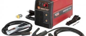
Welding of optical fiber is carried out using special welding machines that allow you to perform the entire range of current operations: from connection to protecting the welded area.
A conventional welding machine will not be suitable for such operations, since it will not be able to provide the master with minimal attenuation at the welding site.
The equipment needed to work with optical fiber operates on the same principle: the ends of the optical fibers are heated to a certain melting point using an electric arc, and then connected together.
It is difficult for an inexperienced welder to accurately adjust the edges of the cables being joined, since they lose functionality if there are errors during adjustment.
When working with fiber optic cables, it is extremely important to pay attention to their colors when welding. It is in addition to the marking and indicates the specific identity of the cable.
Thus, twelve different color claddings are used to identify optical fibers, allowing a specialist to quickly identify the type and purpose of the fiber, even if it is mixed with other cables in a large bundle.
On a note! The problematic issue is that today there is no single international standard for marking fiber optic cables. This situation provokes unpleasant mistakes that young professionals can make.
Common mistakes when welding OM
After studying the instructions for the welding machine and reading this article, you can safely begin welding work. Will it work? If you have a head on your shoulders, your hands grow from the right place and the instructions are followed... Why not, of course it will work out! But this statement is true to the extent that the opposite is also true - it will not do without mistakes. Moreover, let us tell you an annoying fact - they will happen regularly and for some time. Some installers make some mistakes without even realizing they are mistakes.
The thing is that it is perhaps impossible to foresee and prevent all possible undesirable situations when working with optical fiber - because each installer can make new mistakes, as no one has done before.
Let's look at several common mistakes and comment on them.
- Some installers stubbornly refuse to hold the stripper correctly while removing the acrylic coating. We look at Fig. 14, Fig. 15 and Fig. 16:
Fig. 14. The stripper should not be held at a strong angle to the stripping direction - the fiber experiences local bends and may receive microdamage.
Fig. 15. It's even worse!
Fig. 16. But this is correct.
- If you handle the chopped fiber carelessly and proceed as shown in Fig. 17, then when placed in the apparatus we will see a picture like in Fig. 18. And the welding result will be as in Fig. 19:
Fig. 17. Accidentally poked chipped fiber into clothes... Or was it not by accident?
Fig. 18. Accident or not, it doesn’t matter anymore. It is important that dirt sticks to such fiber.
Fig. 19. If welding is done, the result is guaranteed to be disappointing. And don’t let the 0.01 dB “estimate” reassure you. This is a marriage!
- Sometimes on the screen you can see a picture like the one in Fig. 20. Cleaving angle 3.7°! The device signals indignantly, highlighting this circumstance in red. Actually, there is no error here; such a situation can happen sooner or later - as a rule, this means that the cleaver blade has become dull. A mistake would be the decision to ignore the warning about a bad chip and still carry out welding. We didn't.
Fig.20. The angle of the chip is no good. If you weld with such a chip, expect losses.
- A serious mistake is that the shrink sleeve does not cover the edge of the buffer coating (the same is true for acrylic coating). The strength of the fiber near the joint decreases. See Figure 21:
Fig.21. The sleeve moved to the side while being placed in the heater. You can not do it this way!
- And a very amateurish option - the sleeve, which had not had time to cool, was installed in a splice cassette. See Figure 22. It doesn't cost anything to crush hot shrink. And along with it, the fiber inside!
Fig.22. Flattened.
How to avoid this and any other disgrace in your future work? The answer is simple - only practical work experience will give you confidence and teach you to be careful.
And you can take the first steps in this direction quite successfully in editing classes at Educational. In the presence of teachers, you will be able to immediately notice your mistakes, and most importantly, learn not to make them!
More about training
Cable structure
The essence of welding technology is to connect the ends of an optical fiber and then heat them until they melt and join into a single whole.
For those who have worked with glass, this will seem elementary, but you need to keep in mind that the fiber through which data is transmitted has a diameter of 9 microns (10 times thinner than a human hair) and it is required that the signal attenuation does not exceed hundredths of a decibel.
To understand the essence of the welding process, you need to understand the structure of the optical cable. It is a complex structure, in the center of which there is a glass thread with a diameter of 125 microns. This is just a shell of a 9 micron thread made of ultra-pure glass, which is the information carrier.
The outer glass has a different refractive index than the inner glass. Thanks to this, the light spreads only along the inner thread, reflecting from the walls.
To protect the optical fiber from external influences, it is coated with varnish and placed in module tubes with a hydrophobic gel. In addition to this, the modules are covered with a protective film.
As additional protection from moisture, everything is covered with plastic film. Next comes armor made of Kevlar threads or steel wire, which is covered with a thick layer of polyethylene.
What is important to consider?
It may seem that there is nothing complicated at the stage of connecting a connector to an optical adapter. How to plug a plug into a socket. However, no.
Let's look at least from a technology point of view. What is a kit - patchcord/pigtail + adapter? This is the joining of two optical fibers, the thickness of which is approximately equal to the thickness of a human hair. In this case, a connection shift of even 1 micron causes a loss of power.
That is, the cross connection must provide:
- ideally precise contact of cores (fiber optics);
- protection of this ideal contact from external influences - shifts, the appearance of an air gap, etc.;
- mechanical protection of fibers during repeated connection and disconnection;
- mechanical protection of the cable in the connector during bending, pulling, etc.
In particular, this is why so many types of optical connectors have been created. Each manufacturer strived to create the ideal connector specifically for their equipment.
But that's not all the difficulties
To ensure an accurate connection, the tips of the optical connectors must not be cracked (if a crack crosses the optical fiber, the connector must be replaced), dusty or dirty. Even if you just touched it with your finger, the mark must be thoroughly wiped off with an alcohol wipe. Every speck of dust, pollution, etc. - this is weakening, attenuation of the signal, back reflections.
Therefore, optical connectors are regularly wiped with alcohol, and sockets are blown with compressed air or cleaned with special sticks.
The picture on the right shows the tip of the connector after touching it with a finger and after cleaning.
The mechanical strength of connections is ensured differently in each type of connector, but basically it is:
- especially durable connector tip material - ceramics, metal-ceramics;
- protective plastic and metal caps over the connectors;
- latches and position locks both in optical adapters and in “plugs”;
- Kevlar and other reinforcing threads under the sheath of the cable section leading to the connector.
Welders
For welding optical fibers in Russia, devices most often used are from Japanese companies Fujikura, Sumitomo and Chinese Jilong. Japanese manufacturers initially showed themselves excellently in this area, their machines are the best, but the Chinese are stepping on their heels and producing decent welding machines at low prices.
To obtain high-quality welding of an optical fiber, you need a welding machine capable of aligning the fibers not only along the cladding, but also along the core.
They have several servomotors that can move the fiber in all planes. This allows you to achieve the greatest accuracy in connecting fiber optics. Most of the products from the above-mentioned companies can produce high-quality alignment.
Where the requirements are not as stringent as on trunk communication lines, welding machines with sheath adjustment can be used. The optical fiber in these devices is fed through V-shaped grooves.
If there is an eccentricity of the central core or a scratch on the groove, the welding quality will be lower, and accordingly the attenuation will be greater. Japanese devices are universal and work with almost all types of fiber.
Where to buy a high-quality optical fiber splicer?
Contact Komponent JSC if you need to purchase a high-quality fiber optic splicing machine at a reasonable price. The company's specialists will be happy to help you choose the optimal model within your existing budget.
Splicing machines perform welding and heat shrinking of optical fibers in a minimum amount of time. Working with the device is convenient due to the automatic windproof cover and the automation of the shrink oven. Light weight combined with a large capacity built-in battery ensures mobility and the ability to be used anywhere along the cable route. Excellent protection from environmental influences allows welding to be carried out in difficult weather conditions.
You can also buy other equipment used for welding optical fibers from us: compact cleavers and accessories - strippers, electrodes, cleaver blades, holders. All products offered have been tested and appreciated by hundreds of customers in the construction of fiber-optic lines and fiber-optic networks.
Fiber optic cable cutting
The main task when cutting a fiber optic cable is to maintain the length of its components as indicated in the coupling instructions. Therefore, in some cases it is necessary to leave long power components designed to be secured in the coupling, and sometimes this is not necessary. In some cases, you need to make a “pigtail” out of Kevlar and secure it with a screw; it is better not to cut the Kevlar. These nuances depend on the design features of the coupling of each cable. So, the stages of completing the work:
The hydrophobic protective layer is first removed from the fibers. To do this, they are wiped with special wipes: first dry, then treated with alcohol.
It is quite important to follow this rule, since a large amount of hydrophobic material will remain on the first napkins. But when it is no longer possible to remove minor remnants of the protective layer with a dry cloth, alcohol will help
It will easily dissolve hydrophobic particles and instantly evaporate from the surface of the fiber.
It should be noted that the cleanliness of the fibers, especially their ends, is the key to high-quality optical fiber welding. When working with microns, even the slightest contamination is unacceptable! It is imperative to check the fibers for the integrity of the varnish coating and the absence of broken areas
If there is damage to the varnish coating, then it is recommended to redo such a cable (but it should not be broken)
It is imperative to check the fibers for the integrity of the varnish coating and the absence of broken areas. If there is damage to the varnish coating, then it is recommended to redo such a cable (but it should not be broken).
- The coupling kit includes a special heat shrink, which is put on an already cut cable (which beginners often forget about). If the cable will be clamped with rubber and sealant, then heat shrinkage is not needed. To ensure a tight connection between the cable and the coupling, it is recommended to use a hair dryer, a soldering iron, or a torch to shrink it. But the most practical is considered to be a small burner, mounted on a gas canister.
Before you start welding an optical cable, it is recommended to purchase additional coarse sandpaper. This will help ensure better adhesion to the adhesive.
Pros: a) Compactness. b) Touch screen that supports fingers and any stylus. c) Built-in red laser for illumination (this is an option), tester functions and other features. For example, there is a terminal for testing the operation of IPTV (I did not use it).
d) Low price for reflectometers (about 90,000 rubles, in 2010 it cost 80,000). e) Quite a capacious battery. f) USB port for a flash drive (to transfer reflectograms onto it) and mini-USB (to connect the device itself to a computer as a removable drive with a capacity of 1 GB - this is more than enough for reflectograms). g) The body is partially aluminum. g) While working at noon under the hot southern sun, it happened to get very hot - and this did not affect its work. Cons: a) A narrow dynamic range of 34/32 dB (1310/1550 nm), which is why they cannot measure a long line. So, in my experience, this device barely penetrates 40-50 km, then it is no longer enough (the end of the route is drowned in noise and the measurement time stretches to an indecently long time). True, in the memory of the new device, when I received it, there was a very beautiful and not at all noisy reflectogram of a route about 75 km long, but no matter how hard I tried, I could not get such a result on long routes. Maybe, of course, it’s my hands that are crooked, or I didn’t have the patience to wait for an hour for the results of one measurement, or the photocell has already degraded, but one way or another, taking a reflectogram of a path more than 25 km long with this device becomes problematic. In the best case, you will have to wait many minutes for each measurement, which means that the 64-port cross-connect will have to be measured for more than one day. The impression is that when setting the measurement parameters for a route of more than 25 km, the brakes begin to grow exponentially: at the limit of “25 km” you can still work, at 50 it’s almost impossible. Below 25 everything flies. b) Poor quality of assembly and materials: on one device, the Mini-USB port soon fell off for no particular reason and the USB fell off, on the second, after 2 years, the VHL illumination module with red light stopped working, for both devices, after about 2.5 years, it was not particularly intense During operation, breaks appeared in the power cords (both power and low-voltage), I had to take a screwdriver and a soldering iron and resolder the wires, as well as change the plug. When shaking, something heavy dangles inside both devices; it looks like the battery was not secured properly. c) Annoyingly low quality of software. The main disadvantage of this device, may the programmers from Svyazpribor forgive me! There are often strange glitches and unexpected windows with errors, indecently long measurements on large lengths of the route and wild lags when trying to cancel such a started measurement.
Frequent spontaneous shutdowns, reboots and factory resets. It happens that when the device is turned on cold, it does not find the OTDR module (that is, the module of the reflectometer itself) or simply does not complete loading at a certain stage, but if after this error you put the device into sleep mode and wake it up, everything is found. And sometimes it’s not there: once my partner went to another city on a business trip and there the device refused to boot, so I had to use the device of the local team. Upon returning, the device soon started working again. Sometimes a glitch appears in the measurement results, and sometimes in such a cunning and confusing way that it’s not easy to formulate a bug report... You can easily be misled and incorrectly determine the distance to the cliff, so people will go looking for the cliff in the wrong place: the reflectogram is drawn, but how - it’s faster than usual, it’s kind of crooked, and guess what, it’s a glitch, especially if you have no experience working with such a tricky device)) Most likely, what happens is the following: after several normally drawn reflectograms, some of the settings are silently reset, including the set one length range (and the default range is 300 or 500 m on different firmware), the reflectometer begins to draw what it sees at these 300 meters, but for some reason it draws a drop into noise, similar to the end of the route... Or this: on a smaller scale everything normal, but when you set the length scale one step smaller, the working area of the reflectogram is generally drawn somewhere outside the permissible vertical area, and it simply is not in the reflectogram file, only the beginning of the trace, signs of the final peak and noise are visible. During automatic analysis, it can show one route length, but when manually placing the cursors exactly at the beginning and end of the route, the value of the route length will be slightly different. With some special combination of settings and trace parameters, strange dips or shifts appear at the beginning of the reflectogram, due to which the customer may not accept the documentation (I believe this occurs at certain lengths of the measured trace - maybe some wave and resonance effects are processed incorrectly in the fiber, or due to a dirty port in the cross-connect, but this does not happen with other reflectometers).
In the case where a priori only noise should be shown (say, if you start the measurement without unscrewing the cap on the port and without connecting it to the trace), you can draw something similar to a trace, with a working section, an indistinct end and an area of noise. In the case of a poor connection on the connector (dirt at the end of the patch cord) and, accordingly, there is a smooth transition from the initial illumination zone to the route zone, during analysis the reflectometer can place “events” in this place (that is, decide that there are several places there, where the signal attenuates). When measuring at the minimum length range (300 m), the reflectograms are curved and uninformative (although this is probably due to the low sensitivity of the receiver). And so on. Moreover, a reboot does not always help; glitches appear and disappear according to the superposition of the Martian calendar and the phases of the Moon. On one trace the reflectograms are ideal, like those of an expensive device, but on the other trace they are unimportant. Subjectively, more often than not, some of the glitches (not finding the OTDR module) appear in the cold. I would have thought that this was an isolated defect, but I have 2 devices with different firmware and both firmware on both devices are weird about the same. Subjectively, the newer firmware is a little more stable, but also a little slower. In my opinion as a user, the firmware differs only in some interface changes, a modified keyboard and the logic of its operation, as well as a slightly modified logic for drawing reflectograms. This list of software shortcomings also includes extremely inconvenient work with text when naming and renaming files. There is no convenient automation so that, say, by pressing one button, reflectograms are taken one by one at 1310, then at 1550 nm, automatically named according to a flexible template and saved as 2 files in a pre-selected folder. Yokogawa has it. d) Sparse equipment: a tight, short-lived bag, only 1 optical (FC-FC) and 1 copper (8P8C-8P8C) patch cord, USB-mini USB cable, power supply with a removable “computer” cord, disk with software and a brochure ( instructions + passport with verification). The stylus seemed to be included, but it was bad: the “antenna” folding mechanism quickly broke. There is not enough set of patch cords so that each has an FC connector on one side, and on the other - all common standards: FC, SC, LC, ST, FC/APC, LC/APC, SC/APC. It’s bad that the bag is too tight: you can’t put in it a box of napkins, a bottle of alcohol, a bottle of compressed air for blowing out sockets, a compensation coil, an extra pack of cleaning sticks, or a pack of network diagrams. It is difficult to fit what is included in the kit, plus several separately purchased patch cords. e) The case is not lined with rubber and there is no protection from moisture. e) There is no folding frame at the back on which the device can be rested when placed on the table at 45°: either lay it flat or place it perpendicularly. f) The touch screen is very far from the level of modern smartphones in terms of touch processing quality: no multi-touch (but it would be very useful for scaling areas of reflectograms), and in general the Windows CE-like interface is poorly designed for fingers, a stylus is needed (although I got used to it over time and without him). g) Inconvenient work with text on the sensor. At first it is incredibly difficult to select text or place the cursor between certain letters, even with a stylus, because... The accuracy of positioning the point of contact is poor, but over time you get used to this intricate and capricious task. Drag'n'Drop was stuck completely out of place: it gets in the way when working with text, when instead of moving the cursor, pieces of this text begin to be highlighted and moved. The timer that distinguishes a double tap from two single taps is too long, and in general, a double tap to highlight an entire word is also out of the question, especially with the accuracy of the sensor, when the “blinking” of a single tap appears. Well, at least when opening one specific file from a small list, it is not necessary to use a double tap, but you can select the file and click on the “Open” button. Two different firmwares have different keyboards: in one QWERTY, in the second ABCD and the text controls are different (in one you can move the cursor with arrow buttons, in the other you can place the cursor between the desired letters with a stylus or tap), it is inconvenient to switch between one to the other. h) Maybe we shouldn’t count this as a disadvantage, but still: you can’t collapse or close the “measuring” shell and surf in the OS itself.
Weld quality check
During the welding process, it is necessary to pay attention to the shape of the weld arc. Perfect welding is almost invisible to the naked eye
If the arc is crooked, it is recommended to chop off the weld and repeat the work again.
If the welding machine produces significant signal attenuation at the seam site (more than 0.1 dB), then it is better to digest the fibers. But even if the signal loss is insignificant, the total of several welds can still result in signal loss at the other end of the cable.
Reflectometer
The attenuation of the entire optical path, consisting of several couplings and cross-connects, is checked using a reflectometer. This is a measuring device that sends a pulse along an optical path and analyzes its scattering and reflection. With its help, you can see the total length of the path and the signal attenuation in a separate section. This way, it is possible to find out exactly where the fiber optic cable is causing a signal break or significant attenuation. The instrument saves measurements in an electronic file, allowing dispersion analysis to be carried out some time after testing.
Installation of optical connectors using pigtails
Figure 5 – optical pigtails: a) in a dense buffer; b) in a free buffer
An optical pigtail (Pig tail - literal translation - pig's tail) is an optical cable 1.5 m long terminated on one side.
Typically pigtails have a buffer shell diameter of 0.9 mm. Moreover, they are supplied both in a dense buffer (Fig. 5a) and in a free buffer (Fig. 5b). The main difference between these two types of buffer layer is its removal. The dense buffer is removed only together with the 250 micron acrylic coating of the fiber. The floating pigtail buffer is removed separately from the fiber varnish coating.
Figure 6 – optical splice cassette
To save space in the splice cassette, some operators require the 900 micron jacket to be removed from the cable before installation.
A splice cassette is a structural element of any optical distribution box or optical coupling. It has seats for installing KDZS, as well as space for placing a supply of fiber with an allowable bending radius.
Pigtails also differ in the type of optical fiber used in them, the type of housing and the polishing of the installed optical connector.
Figure 7 – optical box (ODF): a) on the operator’s side; b) on the subscriber side
To terminate an optical fiber using a pigtail, you must do the following:
- Place a protective sleeve - KDZS - on one of the fibers to be welded (fiber from a cable or pigtail). It is worth noting that the KDZS (welded joint protection kit) is a product consisting of two tubes (one inside the other) and a metal or ceramic stiffener placed between them. The upper tube shrinks (reduces in diameter) under the influence of temperature, preventing dust and moisture from entering the fiber welding site). Stiffening element – protects the welding site from bending. The most common are KDZS with a length of 40 and 60 mm. However, with the development of Splice On technology, micro KDZS with a length of less than 20 mm are also gaining popularity.
- Remove the buffer layer of the cable fiber and pigtail using a buffer layer stripper
- Wipe the fibers with a lint-free cloth soaked in isopropyl or ethyl alcohol 96%
- Cleaving fibers using a precision cleaver
- Weld the fibers using a welding machine
- Slide the KDZS sleeve (welded joint protection kit) onto the welding site
- Perform heat shrinkage of the KDZS in the oven of the welding machine
- Mark the KDZS using a marker or a special sticker with a serial number
- Install the KDZS into a special clamp on the splice cassette
- Place a supply of optical fibers in a splice cassette
As you can see, the procedure is quite simple. The use of this method of installing connectors on fiber optics is quite justified in operator cross-connections or large distribution boxes. However, on the subscriber side everything is not so simple.
Firstly, on the subscriber side, most often only one, or at most two, fibers are terminated. Using a large ODF (as depicted in Figure 7a) does not make sense.
Second, there is much less space in a small PO box, which results in large bends in the fiber optic cable. And if for pigtails, which are most often made on the basis of the G.657 standard fiber, which is less sensitive to bending, this is not very critical, then for cable fiber (another standard) it is noticeable. Additional signal loss occurs where the fiber bends. This can be easily verified by illuminating such a fiber with a damage visualizer (red light source).
Figure 8 – loss of optical signal power at the macrobend location
Therefore, on the subscriber side, it is recommended to terminate the cable using Splice-On connectors (the KDZS is located in the shank of the connector itself) with a minimum number of spare loops.
Nuances of fiber optic welding
If the cable is multicore, the optical fiber sheath is made in different colors to make it easier to weld individual conductors. After this, they are placed in a special coupling. In the process of chipping the conductor, glass particles are formed; they are collected immediately, because it is easy to be injured by the transparent fiber.
Be careful when cleaning the insulation - the wire core is very fragile. If there is any damage, you will have to start the process again
Before inserting the ends into the welding machine, they are thoroughly degreased and dried; the work area should not be dusty. Any extraneous inclusion increases the loss of power of the transmitted signal.
Installation of reinforced Splice On connectors for installation on outdoor optical cable
Reinforced Splice On connectors are a unique solution for organizing optical cable distribution in FTTx and PON networks. They are installed using a welding machine on street cables of round (5.0 mm and 5.8 mm) and flat (8.1×4.5 mm and 5.4×3.0 mm) sections. Thanks to the design features of Splice On, the connectors are resistant to temperature, sun and precipitation, so the distribution box can be installed directly on a light pole.
Features of reinforced Splice On connectors:
- Low insertion loss: ≤0.15dB
- Return Loss: >60 dB (APC)
- Hull resistance to direct tension (0°): 20 kgf / 10 min
- Adapter resistance to direct tension (0°): 11.3 kgf / 60 sec
- Adapter resistance to lateral stretch (0°): 6.8 kgf / 60 sec
- Resistance to water penetration: 3.04 m for at least 7 days
The technology for installing a reinforced connector on an outdoor fiber-optic cable is demonstrated in the video:
As follows from the video, the dimensions of the external heat-shrinkable tubes do not fit into the standard furnace of the welding machine. To shrink them, you can use a gas burner (as in the video) or a special shrink oven.
Fiber Splicing Equipment
Choosing a welding machine for fiber-optic lines comes down to determining the type of welding:
- manual;
- semi-automatic;
- automatic.
Manual devices do not allow high-quality and quick work on connecting cables. The labor-intensive mixing process is controlled under a microscope.
It was replaced by semi-automatic equipment. All work is done under a microscope, and the operator can evaluate the quality of the automatic connection of the welding site. This device significantly saves the technician’s time.
A negative characteristic of the device is that optical cords cannot be welded. This part of the work is done manually by the master.
A positive assessment of the device is its low cost compared to fully automatic welding machines.
A fully automated device has recently appeared on the market. It allows you to significantly save operator time. The built-in microscope allows the master to control the cooking process. The disadvantage of modern models is their high price.
welding equipment
Welding optics requires equipment designed for this purpose. Welding machines allow you to carry out the entire welding process, which is fully automated. It is controlled by operator actions.
Main elements of the device:
- power unit;
- the electronic unit;
- mechanical part;
- monitor.
There are several modifications of welding machines. Each model has unique software. When choosing a machine for splicing fibers, preference should be given to those models that ensure the alignment of the fibers in the center, which guarantees precise alignment of their ends. You should also pay attention to such a parameter as the speed at which welding can be carried out.