What is PV 3 wire
The PV 3 wire is a copper conductor, which is insulated with a layer of PVC (polyvinyl chloride).
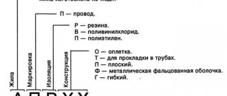
This type of wire is used almost everywhere: connecting electrical mechanisms and devices, laying power networks and lighting networks. Its main difference from its predecessor PV 1 is that it is more flexible. PV 3 has more outstanding properties, which makes it capable of withstanding all kinds of bends and turns during laying without loss of quality. PV 1 is the least flexible of all conductors. The abbreviation is explained as follows:
- The letter "P" is the designation of the wire. There is, for example, “Sh” - cord or “K” - cable;
- The letter “B” is a determination of the presence of a certain type of insulation. In this case it is polyvinyl chloride, which is also simply called "vinyl". Hence the letter “B”;
- The number “3” indicates the flexibility class of the wire. As has already become clear, PV 1 is the most inflexible wire, while PV 6 is the most flexible. Three is somewhere in the middle.
Important! According to outdated standards, the name of any wire may be preceded by another letter, which should decipher what exactly the conductor’s veins are made of. For example, if there is the letter “A”, then it is aluminum, and if it is “M”, then it is copper.
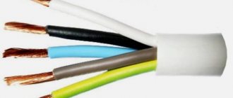
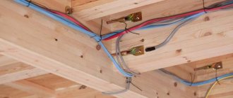
Cord device
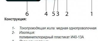
Decoding of PV markings
The main structural features of PV3 can be learned from its factory markings. According to generally accepted principles, PV-3 is deciphered as follows:
- The absence of the letter A before the marking indicates that copper conductors are used as a current-carrying element;
- The letter P means that this is a wire, not a cable;
- The letter B indicates that the insulating layer is made of polyvinyl chloride or a vinyl derivative;
- The number 3 indicates the flexibility class of the wire.
Regarding the flexibility class, it should be noted that there are six classes in total, in which the first is the least flexible, and the sixth is the most flexible wire. Therefore, PV3 has average flexibility among other brands. The level of flexibility is ensured due to the design features of the wire.
Consider the example of marking PV-3-2.5, it indicates that this brand of wire is copper, with one layer of vinyl insulation, has a third category of flexibility and a core cross-section of 2.5 mm2.
Modern analogue.
Today you can find a domestic analogue of PV3 - this is the PuGV wire. The first of them is manufactured on the basis of the Soviet standard GOST 6323-79, the second is produced on the basis of the newer GOST 31947-2012. The only difference is that PuGV has increased flexibility compared to PV3, but otherwise they are completely identical.
Design elements of PV3 wires
Each cord or cable has certain design features. The type and number of elements are influenced by the purpose, operating conditions, and maximum voltage level. The structural details of the PV 3 installation wire are:
- copper core (according to GOST No. 22483 can be solid or multi-wire);
- external protection (insulating layer).
Explanation of the name of the wire PV-3
Despite the minimal number of elements, the wire has high technical characteristics, thanks to which it is used in various fields. For example, the PV 3 grounding cable is used in residential buildings and electrical devices.
Specifications
All characteristics of PV3 can be conditionally divided into mechanical, thermal and electrical, which determine its ability to fully solve the assigned tasks. Check them all out:
- Permissible wire bending radius – determines by what amount, depending on the parameters of the brand, a given conductor can be bent. This parameter is checked immediately after production and entered into the product passport. For PV3, the radius ratio is observed when laying at least 5 diameters of the outer part of the wire itself.
Rice. 4: bend radius - Permissible mechanical elongation of insulation - characterizes the ability of the polyvinyl chloride layer to change its geometric parameters, but not less than 50% of the existing length. So that the wire can be easily bent within a given range.
- Operating temperature is the permissible temperature limit at which normal operation of the wire is allowed without loss of its declared parameters. In relation to this brand, the nominal limits range from – 50°C to +70°C.
- Short-term overheating - exposure is allowed in an emergency or when the system is overloaded up to 150°C. At the same time, the insulation maintains dielectric and mechanical parameters.
- Resistance of the insulating layer to single impacts , acoustic and vibration influences. Due to its narrow specialization, such characteristics of PV3 are not relevant for the average consumer; they are important for communication lines and specific equipment.
- Electrical insulation resistance is tested at the manufacturing stage by immersing the wire in water and then applying a voltage of 2.5 kV for 5 minutes.
- Conductivity of the core is determined by the resistance of the copper conductor; this value is standardized for each brand separately and can vary depending on the temperature of the wire.
Table: dependence of PV-3 parameters on the number of wires and their cross-section.
| Nominal cross-section (mm2) | Minimum number of wires in the core (pcs) | Wire outer diameter (mm) | Maximum electrical resistance of the core at direct current and temperature 20°C. (MOhm/km) |
| 0,5 | 7 | 2,0 | 39,6 |
| 0,75 | 7 | 2,2 | 25,5 |
| 1,0 | 7 | 2,3 | 21,8 |
| 1,5 | 7 | 2,8 | 14,0 |
| 2,0 | 15 | 3,1 | 9,97 |
| 2,5 | 19 | 3,5 | 8,05 |
| 4,0 | 19 | 4 | 4,89 |
| 6,0 | 19 | 4,6 | 3,11 |
| 10 | 49 | 6,3 | 2,0 |
| 16 | 49 | 7,5 | 1,21 |
| 25 | 77 | 9,9 | 0,809 |
| 35 | 105 | 10,9 | 0,551 |
| 50 | 144 | 13,3 | 0,394 |
| 70 | 210 | 15,5 | 0,277 |
| 95 | 285 | 17,6 | 0,203 |
| 120 | 360 | 19,5 | 0,162 |
| 150 | 444 | 21,2 | 0,129 |
| 185 | 555 | 23,8 | 0,104 |
| 240 | 760 | 27,1 | 0,0808 |
It should be noted that despite the lower operating temperature limit of – 50°C, it is allowed to lay the wire in conditions not lower than – 15°C, since the insulation becomes fragile and can be easily damaged when bent. If you need to lay PV3 in a cold climate below – 15°C, it needs to be additionally heated.
Table 3
| Number and nominal cross-section of cores, mm2 | Maximum external dimensions, mm | Number and nominal cross-section of cores, mm2 | Maximum external dimensions, mm | ||
| thickness | width | thickness | width | ||
| 2×0,75 | 2,6 | 6,4 | 3×0,75 | 2,6 | 10,2 |
| 2×1,0 | 2,8 | 6,8 | 3×1,0 | 2,8 | 10,8 |
| 2×1,2 | 3,1 | 7,4 | 3×1,2 | 3,1 | 11,7 |
| 2×1,5 | 3,3 | 7,8 | 3×1,5 | 3,3 | 12,3 |
| 2×2,0 | 3,7 | 8,6 | 3×2,0 | 3,7 | 13,5 |
| 2×2,5 | 3,9 | 9,0 | 3×2,5 | 3,9 | 14,1 |
| 2×3,0 | 4,0 | 9,2 | 3×3,0 | 4,0 | 14,4 |
| 2×4,0 | 4,4 | 10,0 | 3×4,0 | 4,4 | 15,6 |
| 2×5,0 | 4,6 | 10,4 | 3×5,0 | 4,6 | 16,2 |
| 2×6,0 | 4,9 | 11,0 | 3×6,0 | 4,9 | 17,1 |
Mechanical properties
Determine the scope of application and operating conditions:
- Flexibility. A remarkable property that increases operational value and efficiency of use. The cross-section of each wire is the same, the number in the set determines the degree of flexibility. According to GOST 22483-77 for PV 3 wire, the wire diameter is 0.79 mm. For small cross-section cables, the wire diameter can be 0.53 mm and the minimum number of cores is 7, which corresponds to the fourth class of flexibility. The sum of the cut areas of the cores is the nominal cross-section of the cable, indicated in the technical specifications. The permissible bending radius is at least five outer diameters;
- Strength. The concept of the conductor design in the form of a cable provides, in addition to flexibility, increased mechanical strength and increases the ability to bear loads. The insulation material, which can be two-layer, can successfully withstand various mechanical influences without loss of useful properties and destruction. Linear tension until the moment of failure is 150% of the original length, that is, it lengthens one and a half times. The thickness of the insulation depends on the diameter of the core;
Nominal core cross-section, mmNominal insulation thickness, mm
| From 0.5 to 1.0 incl. | 0.6 |
| 1.5 | 0.7 |
| from 2.5 to 6 | 0.8 |
| 10.0 and 16.0 | 1.0 |
| 25.0 and 35.0 | 1.2 |
| 50.0 and 70.0 | 1.4 |
| 95.0 and 120.0 | 1.6 |
| 150 | 1.8 |
| 185 | 2.0 |
| 240 | 2.2 |
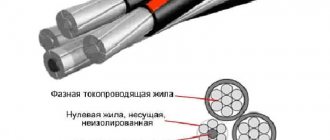
- Colors. Using the right color is very important and must comply with generally accepted standards. Creates convenience, reduces labor costs for dialing, troubleshooting for installers and repairmen, and promotes the creation of safe conditions for handling electricity. The colors are determined by the PUE and the European standard: o Yellow-green, yellow or green - intended for connection to the ground contact, the international designation of the contact is “PE”; o Blue or cyan connects the neutral, or “zero” (“N”); o The remaining colors are designated by “phase” (“L”) and are chosen arbitrarily.
In three-phase versions, it is customary to mark the phases:
- A – white;
- B – black;
- C – red.
DC circuits use different markings. Here white, black is “plus”, red is always, the rest are, as necessary, “minus”;
- Temperature. High electrical safety indicators are ensured by the presence of two layers of elastic insulation made of polyvinyl chloride modifier. Allows flawless operation in the ambient temperature range -50⁰С - +35⁰С, allowing long-term operation when the core is heated to +70⁰С. Installation, to prevent the formation of shell cracks, is prohibited when the air is cooled below -15⁰С.
ACCEPTANCE RULES
3.1. The rules for acceptance of wires must comply with GOST 26445 and this standard.
3.2. Acceptance tests
3.2.1. The volume of a batch of wires is no less than 300 m and no more than 100 km.
3.2.2. The composition of the tests and the sequence of their conduct within each group must correspond to those indicated in table. 9.
Table 9
| Items | ||||
| Test group | Type of test or inspection | technical requirements | control methods | |
| GOST 6323 | GOST 6323 | GOST 26445 | ||
| C—1 | Checking the appearance | 2.4.2; 2.4.3; 2.4.6 | — | 4.2.1 |
| S-2 | Checking design dimensions | 2.4.1; 2.4.2; 2.4.3—2.4.7 | 4.2.1 | — |
| S—3 | Voltage test | 2.5.2 | 4.3.1 | — |
| C—4 | Checking the electrical resistance of current-carrying conductors | 2.5.1 | — | 4.3.1 |
| S—5 | Checking labeling and packaging | 5.2; 5.3 | — | 4.6.1 |
| S-6 | Bend strength test | 2.7.2 | 4.5.1 | — |
3.2.3. Tests for groups C-1, C-2, C-4 and C-6 are carried out sequentially on one sample, for groups C-3 and C-5 - on independent samples.
3.1—3.2.3. (Changed edition, Amendment No. 3).
3.2.4. To carry out tests in groups, selective single-stage control is used with an acceptance number C = 0.
The sample size for groups S-1, S-2, S-4 and S-5 is 5%, for group S-3 - for category EI-2 - 100%, for category EI-1 - 2%, but not less three bays or construction lengths, for group C-6 - three samples from batches.
(Changed edition, Amendment No. 3, 4).
3.3. Periodic testing
3.3.1. The composition of the tests and the sequence of their conduct within each group must correspond to those indicated in table. 10.
Table 10
| Items | ||||
| Test group | Type of test or inspection | technical requirements | control methods | |
| GOST 6323 | GOST 6323 | GOST 26445 | ||
| P—1 | AC voltage test | 2.5.3 | 4.3.2 | — |
| Checking the electrical resistance of wire insulation | 2.5.4; 2.5.5 | 4.3.3 | — | |
| Cold resistance test | 2.6.9 | 4.4.5 | — | |
| P—2 | Determination of resistance to cracking and deformation at elevated temperatures | 2.6.13 | 4.4.24 | |
| P—3 | Checking the physical and mechanical properties of insulation | 2.7.1 | — | 4.5.6 |
| I 1 -fc. | Flame retardation test | 2.6.12 | — | 4.4.21 |
3.3.2. Tests are carried out once every 12 months.
3.4. The consumer assesses the compliance of the electrical parameters of the wires with the requirements of this standard (clauses 2.5.2, 2.5.4) during incoming inspection within 12 months from the date of manufacture according to the standards established for the acceptance and delivery of wires.
3.3—3.4. (Changed edition, Amendment No. 3).
3.5, 3.6. (Excluded, Amendment No. 3).
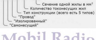
What does marking mean?
PV-3 wires of different sections
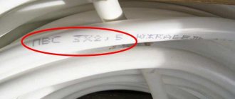
The cable is used in different situations - installation of electrical wiring, instruments, devices. There are different types and types of wires, the characteristics of which are indicated on the outside (on the “rubber” part). Symbols - letters, numbers, signs - allow you to determine:
- the number of cores inside and their material;
- insulating type;
- cross-section - cross-sectional area of the element - from 3.5 to 24 cm square;
- permissible voltage - nominal values of electrical indicators;
- attitude to environmental influences - humidity, heat;
- features of the internal design;
- flexibility - usually marked with numbers from 1 to 6, PV3 wire has an average rating.
Design features are also reflected in the markings. For example, the solidity or multi-wire nature of the internal element, the presence of insulation. Additionally, the type is indicated - wire, cable or cord.
Design features
Wire design PV-1
PV-1 is a single-core wire. Can be used to connect only one equipment. An electrical part is made from high-quality copper, which is pre-tinned.
The PV has an extremely simple design. Includes the following elements:
- An insulating material covering the surface of a wire. Consists of polyvinyl chloride. Has a color marking, which is selected by the customer, if it is not a grounding cable.
- The current-carrying wire is made of copper. Its structure depends on the cable cross-section.
In the range from 0.5 to 10 mm2, the cores are cast; above that, multi-wire cores can be used.
Mark dimensions of wire PV3
- PV3 0.5
- PV3 0.75
- PV3 1.0
- PV3 1.2
- PV3 1.5
- PV3 2.0
- PV3 2.5
- PV3 3.0
- PV3 4.0
- PV3 5.0
- PV3 6.0
- PV3 8.0
- PV3 10
- PV3 16
- PV3 25
- PV3 35
- PV3 50
- PV3 70
- PV3 95
- PV3 120 *
- PV3 150 *
- PV3 185 *
- PV3 240 *
- PV3 300 *
- PV3 400 *
* Mark dimensions are not provided for in regulatory documentation.
Table 6
| Nominal core cross-section, mm2 | Estimated mass 1 km p | ewater, kg, brands | |||
| Automatic reclosing | PV1 | PV2 | PVZ | PV4 | |
| 0,5 | — | 8,5 | — | 9,0 | 10 |
| 0,75 | — | 10,5 | — | 12 | 12 |
| 1,0 | — | 13,5 | — | 14 | 15 |
| 1,2 | — | 17 | — | 18 | — |
| 1,5 | — | 20 | — | 20 | 20 |
| 2,0 | 13,5 | 26 | 28 | 28 | — |
| 2,5 | 15,5 | 30 | 31 | 31 | 31 |
| 3,0 | 18 | 38 | 41 | 38 | — |
| 4,0 | 21 | 45 | 48 | 48 | 48 |
| 5,0 | 24,5 | 55 | 62 | 62 | — |
| 6,0 | 28,5 | 65 | 69 | 70 | 70 |
| 8,0 | 39,5 | 90 | 94 | 94 | — |
| 10,0 | 47 | 108 | 116 | 116 | 120 |
| 16,0 | 66 | 172 | 177 | 182 | — |
| 25,0 | 114 | 274 | 285 | 287 | — |
| 35,0 | 146 | 366 | 370 | 378 | — |
| 50,0 | 202 | 490 | 518 | 520 | — |
| 70,0 | 266 | 695 | 705 | 730 | — |
| 95,0 | 366 | 965 | 975 | 985 | — |
| 120,0 | 422 | — | — | — | — |
Electrical parameters
The basic values of quality characteristics sufficient for practical use are the electrical insulation strength and the resistance of the conductive copper core, standardized by GOST to one kilometer of length. The values are presented in the table.
Number of cores X cross-section, mm 2 External diameter (size), mm. Wire weight, kg/km. Diameter of the conductor, mm. Maximum electrical resistance to direct current of the conductor (at +20°C), Ohm/km. Electrical resistance of wire insulation, kOhm/km, not less (at +70°C)
| 1×0,75 | 2.31 | 11.4 | 1.11 | 24.5 | 11 |
| 1×1,0 | 2.46 | 13.8 | 1.26 | 18.1 | 10 |
| 1×1,5 | 2.96 | 20.6 | 1.56 | 12.1 | 10 |
| 1×2,5 | 3.7 | 34.3 | 2.1 | 7.41 | 9 |
| 1×4,0 | 4.2 | 49.4 | 2.6 | 4.61 | 7 |
| 1×6,0 | 4.8 | 70.6 | 3.2 | 3.08 | 6 |
| 1×10,0 | 6 | 110 | 4 | 1.83 | 5.6 |
| 1×16,0 | 7.8 | 184 | 5.8 | 1.21 | 4.6 |
| 1×25,0 | 9.6 | 285 | 7.2 | 0.809 | 4.4 |
| 1×35,0 | 11.4 | 401 | 9 | 0.551 | 3.8 |
It can be seen that with an increase in the nominal cross-section, the maximum current resistance decreases, the permissible current load and the maximum connected load power increase. The physics of operation of alternating current circuits is manifested by mutual interference of the electromagnetic field. It is important to consider the number of wires in a joint installation. The table illustrates this. PV 1, shown in the table, differs from PV 3 in the presence of a single solid core rather than a twisted one, that is, only flexibility.
The electrical strength of PV 3 is guaranteed to allow successful operation in alternating current (frequency up to 400 Hz) and direct current networks up to 1000 volts inclusive. Insulation testing is carried out with an increased voltage of 2500V.
The section ends with a summary table of the main technical characteristics of PV 3. The data given in it is sufficient for practical use:
| Air humidity at 35 0 C [%] | 100 |
| Warranty period [month] | 24 |
| Test AC voltage 50 Hz for 15 min. After staying in water for 24 hours [B] | 2500 |
| Maximum operating temperature of the core [0 C] | 70 |
| Rated voltage U0/U [V] | -15 |
| Bending radius of cables [outer diameters] | 450/750 |
| Construction length, not less [m] | 10 |
| Ambient temperature, upper limit [0C] | 100 |
| Ambient temperature, lower limit [0 C] | +35 |
| Electrical insulation resistance, not less than [Mom*km] | -50 |
| 1.0 |
GOST 6323-79
Wires with copper and aluminum or aluminum-copper conductors with insulation made of polyvinyl chloride plastic for voltages up to 450 V (for networks up to 450/750 V) with a frequency of up to 400 Hz or constant voltage up to 1000 V are intended for electrical installations with stationary installation in lighting and power networks , as well as for the installation of electrical equipment, machines, mechanisms and machine tools.
Type of climatic modification OM2, HL2.
The brands, names and primary areas of application of wires are given in table. 1.
Scope of application
The scope of application of PV-3, on the one hand, is quite broad, but on the other hand, it is very narrow. The whole point is that it is a single wire. It can, according to GOST, be used for electrical wiring, lighting, connecting various installations inside both residential and non-residential premises, but it is more convenient to carry out power installation with cables with two or more conductive cores - for single-phase and three-phase connections, respectively.
Therefore, at present, one of the main tasks of PV-3 (PuGV) is the grounding connection, where a single conductor is required. In some cases, they may connect the neutral. A bundle of several wires of different colors can be used instead of a common cable where flexibility is primarily required. It is also often used in the assembly of power cabinets, for connecting automatic machines, contactors and RCDs, in industry - where for some reason single conductors are required. In this case, the wire must be connected only using a crimp lug - pointed or in the form of a loop, since otherwise the wire may burn out.
It can also be used to create jumpers.
PV-3 has a voltage limitation - 450 V for alternating current or 1000 V for direct current. To connect powerful consumers, it is recommended to use it with caution, carefully selecting the appropriate cross-section.
When used, the cable must be placed in a corrugated pipe, cable duct or armored sheath. Laying in the ground or embedding into a wall is not allowed, since during excavation or repair and construction work it can easily be damaged or even cut down. The protective sheath of this type of conductor is designed to resist only minor mechanical stress.
Open installation with staples is permitted as a temporary measure, but nothing more. It is not used outdoors, including the pulling method. Firstly, it is not self-supporting, and secondly, polyvinyl chloride gradually decomposes under the influence of direct sunlight.
If you have additional equipment, the wire can be used as a heating element - for heating frozen water pipes, and the like.
Its main advantage is lightness and flexibility. The minimum bend radius is 10 outer diameters, or exactly 90 degrees.
Note: modern PuGV has a higher flexibility class than its ancestor PV-3 - fifth.
This type of wire is moderately resistant to fire. When laid alone, it does not support combustion; in case of a short circuit, it melts, but does not spread fire. However, PV-3 is not fire-resistant wire and cannot be used in areas of increased explosion and fire hazard.
Scope, operation
The parameters that the PuGV wire has correspond to the standard. This allows it to be used as an installation device in fixed networks. The insulation properties, strength and huge temperature range allow for installation in open and hidden ways. The open method will require minimal protection with a cable duct or corrugated hose. It can be laid under plaster, in construction voids, without additional protection. Flexibility will be fully demonstrated positively when passing the laying route with numerous turns of channels and gutters, pipes and cable ducts.
For inputs to objects and switching on sockets, it is better to use a hard wire, but the PuGV wire is good for connecting devices and equipment that are not permanently fixed. It is in great demand when laying lighting networks. In places where lighting fixtures are connected, a rigid conductor often breaks.
Using a soft conductor when connecting to a terminal screw, according to the PUE, requires additional hassle. The stripped ends must be tinned or crimped with special tips that prevent thin wires from fraying.
The use of the wire mainly determines the type of manufacture for fire safety:
| Type of execution | Designation | Advantageous Applications |
| Does not propagate fire when laid alone with insulation and sheath made of polyvinyl chloride plastic. | Without designation | Laying single lines and performing power supply circuits for pantographs located indoors |
| Insulation and shell made of polyvinyl chloride plastic compound of reduced fire hazard with reduced smoke and gas emissions | ng-LS | Group laying of lines in indoor (closed) electrical installations. For electrical wiring in residential and public buildings |
| Reduced smoke and gas emissions, with insulation and shell made of halogen-free polymer compositions | ng-HF | Lines and electrical wiring for group and single installation in office premises equipped with computer and microprocessor equipment, entertainment complexes and sports facilities |
| Insulation and shell made of polyvinyl chloride plastic compound of reduced fire hazard with reduced smoke and gas emissions and low toxicity of combustion products | ng-LSLTx | For electrical wiring in public buildings, in buildings of preschool educational institutions, specialized homes for the elderly and disabled, hospitals and children's boarding schools |
| Reduced smoke and gas emissions, with insulation and shell made of halogen-free polymer compositions with low toxicity of combustion products | ng-HFLTx |
A relatively small increase in the purchase price of modified grades of wire will pay off by guaranteeing the safety of people.
The disadvantage of a single-core design is eliminated by using the KUGV installation cable.
Installation and operation
The PV 3 (PUGV) cable, due to its good flexibility, can be laid in any conditions. Vinyl coating is flame retardant. One of the advantages of PUGV is its immunity to destructive fungi and mold formations.
The installation wire PV 3 for installation in conditions where the ambient temperature is below -150C must be warmed up. This is done using various heating equipment. If this is not done, the “frozen” PVC shell may crack, especially at the bends. As a result, the insulation will be broken and the conductor will become unusable.
According to the installation technology, the PV 3 installation wire must be installed inside equipment that is well protected from high levels of humidity and condensation accumulation. PUGV is placed in cable ducts, boxes, sleeves and inside other protective devices. The practice of laying cables in the voids of reinforced concrete structures is also known.
Operation of PV 3 wiring is allowed in the ambient temperature range from -500C to +500C. The selection of the cross-section of the cores and the strength of the flowing current should not allow the conductor to heat above +700C.
MANUFACTURER'S WARRANTY
GOST 1508-78 control cables with rubber and plastic insulation.
technical specifications (as amended n 1, 2, 3, 4, 5) 7.1. The manufacturer guarantees that the wires comply with the requirements of this standard subject to the conditions of transportation, installation, operation and storage.
The warranty period is two years from the date of commissioning of the wires.
(Changed edition, Amendment No. 3, 4).
APPENDIX 1 Mandatory
OKP codes and control numbers (CC)
Table 11
| Wire brand | Code | CC |
| PV1 | 35 5113 0100 | 08 |
| PVZ | 35 5113 0300 | 02 |
| PV2 | 35 5113 2000 | 03 |
| PV4 | 35 5113 2100 | |
| PV1—HL | 35 5113 2800 | 01 |
| PVZ-HL | 35 5113 2900 | 09 |
| PV2—HL | 35 5113 3000 | 10 |
| PV4—HL | 35 5113 3400 | 09 |
| AP V | 35 5133 0100 | 07 |
| APV-HL | 35 5133 0600 | 03 |
| ppv | 35 5313 0100 | 05 |
| APPV | 35 5333 0100 | 04 |
Note. Set OKP code for PV1u brand wire with a cross section of 1.0 mm2 to 35 5113 0121.
Table 12
| Nominal core cross-section, mm2 | The value of the ninth and tenth digits of the OKP mark-size of wires PV1, PV2, PVZ, PV4, APV | Nominal core cross-section, mm2 | The value of the ninth and tenth digits of the OKP mark-size of wires PV1, PV2, PVZ, PV4, APV |
| 0,5 | 01 | 6,0 | 11 |
| 0,75 | 02 | 8,0 | 12 |
| 1,00 | 03 | 10,0 | 13 |
| 1,2 | 04 | 16,0 | 14 |
| 1,5 | 05 | 25,0 | 15 |
| 2,0 | 06 | 35,0 | 16 |
| 2,5 | 07 | 50,0 | 17 |
| 3,0 | 08 | 70,0 | 18 |
| 4,0 | 09 | 95,0 | 19 |
| 5,0 | 10 | 120,0 | 20 |
Table 13
| Number and nominal cross-section of cores, and x mm2 | The meaning of the ninth and tenth characters of the OKP code of the mark-size of wires of the PPV and APPV brands | Number and nominal cross-section of cores, and x mm2 | The meaning of the ninth and tenth characters of the OKP code of the mark-size of wires of the PPV and APPV brands |
| 2 x 0.75 | 01 | 3 x 0.75 | 11 |
| 2 x 1.0 | 02 | 3 x 1.0 | 12 |
| 2 x 1.2 | 03 | 3 x 1.2 | 13 |
| 2 x 1.5 | 04 | 3 x 1.5 | 14 |
| 2×2,0 | 05 | 3 x 2.0 | 15 |
| 2×2,5 | 06 | 3 x2.5 | 16 |
| 2 x 3.0 | 07 | 3 x 3.0 | 17 |
| 2 x 4.0 | 08 | 3 x 4.0 | 18 |
| 2x 5.0 | 09 | 3 x 5.0 | 19 |
| 2 x 6.0 | 10 | 3 x 6.0 | 20 |
APPENDIX 1. (Changed edition, Amendment No. 3, 4).
APPENDIX 2 Information
Table 14
Maximum outer diameters of current-carrying wire cores
| Nominal current cross-section of the conductor, mm2 | Wire brand | |||
| PV1, APV, APPV, PPV | PV2 | pvz | PV4 | |
| 0,5 | 0,82 | __ | 0,96 | 0,95 |
| 0,75 | 0,99 | — | U7 | 1,20 |
| 1,00 | 1,15 | — | 1,26 | 1,35 |
| 1,2 | 1,27 | — | 1,49 | — |
| 1,5 | 1,40 | — | 1,62 | 1,65 |
| 2,0 | 1,62 | 1,86 | 1,95 | — |
| 2,5 | 1,80 | 2,07 | 2,26 | 2,4 |
| 3,0 | 2,02 | 2,4 | 2,35 | — |
| 4,0 | 2,26 | 2,61 | 2,7 | 2,95 |
| 5,0 | 2,54 | 3,0 | 3,0 | — |
| 6,0 | 2,76 | 3,28 | 3,3 | 4,15 |
| 8,0 | 3,23 | 3,7 | 3,75 | — |
| 10,0 | 3,61 | 4,15 | 4,15 | 4,65 |
| 16,0 | 5,16 | 5,35 | 5,95 | — |
| 25,0 | 6,48 | 6,95 | 7,9 | — |
| 35,0 | 7,62 | 7,85 | 8,95 | — |
| 50,0 | 9,15 | 9,25 | 11,8 | — |
| 70,0 | 10,75 | 10,9 | 13,9 | — |
| 85,0 | 12,7 | 12,9 | 15,3 | — |
| 120,0 | 14,4 | — | — |
APPENDIX 2. (Changed edition, Amendment No. 3).
APPENDIX 3 Information
Table 15
| Nominal | Estimated weight of 1 km of wire, | kg, marks | |||
| core cross-section, mm2 | Automatic reclosing | PV1 | PV2 | pvz | PV4 |
| 0,5 | 8,5 | — | 9,0 | 10 | |
| 0,75 | _ | 10,5 | — | 12 | 12 |
| 1,0 | _ | 13,5 | — | 14 | 15 |
| 1,2 | — | 17 | — | 18 | — |
| 1,5 | _ | 20 | — | 20 | 20 |
| 2,0 | 13,5 | 26 | 28 | 28 | — |
| 2,5 | 15,5 | 30 | 31 | 31 | 31 |
| 3,0 | 18 | 38 | 41 | 38 | — |
| 4,0 | 21 | 45 | 48 | 48 | 48 |
| 5,0 | 24,5 | 55 | 62 | 62 | — |
| 6,0 | 28,5 | 65 | 69 | 70 | 70 |
| 8,0 | 39,5 | 90 | 94 | 94 | — |
| 10,0 | 47 | 108 | 116 | 116 | 120 |
| 16,0 | 66 | 172 | 177 | 182 | — |
| 25,0 | 114 | 274 | 285 | 287 | — |
| 35,0 | 146 | 366 | 370 | 378 | — |
| 50,0 | 202 | 490 | 518 | 520 | — |
| 70,0 | 266 | 695 | 705 | 730 | — |
| 95,0 | 366 | 965 | 975 | 985 | — |
| 120,0 | 442 | — |
Table 16
| Number and nominal cross-section of cores, | Estimated weight of 1 km of wire, kg, grades | |
| n X mm2 | PPV | Automatic reclosing |
| 2×0,75 | 21,9 | — |
| 2 x 1.0 | 29,5 | — |
| 2 x 1.2 | 34,3 | — |
| 2 x 1.5 | 39,8 | — |
| 2 x 2.0 | 52,5 | 27,5 |
| 2x 2.5 | 62 | 31,5 |
| 2x 3.0 | 76 | 36,5 |
| 2 x 4.0 | 92,4 | 43,2 |
| 2 x 5.0 | — | 49,2 |
| 2×6 | — | 58 |
| 3 x 0.75 | 33,2 | — |
| 3 x 1.0 | 44,6 | — |
| 3 x 1.2 | 51,1 | — |
| 3 x 1.5 | 60,0 | — |
| 3×2,0 | 79 | 41,5 |
| 3×2,5 | 94 | 48 |
| 3 x 3.0 | 112 | 53,5 |
| 3 x4.0 | 137 | 64 |
| 3 x 5.0 | — | 74 |
| 3 x 6.0 | — | 86,5 |
APPENDIX 3. (Introduced additionally, Amendment No. 3).
INFORMATION DATA
1. DEVELOPED AND INTRODUCED by the Ministry of Electrical Industry DEVELOPERS
Yu.K. Kabalyan, L.G. Atabekyan, Ph.D. tech. sciences
2. APPROVED AND ENTERED INTO EFFECT by Resolution of the USSR State Committee for Standards dated July 24, 1979 No. 2716
3. INSTEAD GOST 6323-71
4. ST SEV 587-87 has been fully introduced into the standard
5. The standard is fully compliant with IEC 227-3
6. REFERENCE REGULATIVE AND TECHNICAL DOCUMENTS
| Designation of the referenced technical document | Item number |
| GOST 20.57.406—81 | 4.4.4, 4.4.5, 4.4.6 |
| GOST 1579—93 | 4.5.1 |
| GOST 2990—78 | 4.3.1, 4.3.2 |
| GOST 3345—76 | 4.3.3 |
| GOST 5151—79 | 5.3.1 |
| GOST 5960—72 | 2.4.10 |
| GOST 12177—79 | 4.2.1 |
| GOST 15150—69 | 2.2, 5.4.1, 5.4.2 |
| GOST 17491—80 | 4.5.2 |
| GOST 22483—77 | 2.4.1, 2.5.1 |
| GOST 23286—78 | 2.5.2, 4.3.1 |
| GOST 25018—81 | 4.4.4 |
| GOST 25706—83 | 4.2.1 |
| GOST 26445—85 | 2.1, 3.1, 3.2.2, 3.3.1, 4.1, 5.1 |
| TU 16.K71—087—90 | 2.4.10 |
| TU 16.K71—088—90 | 2.4.10 |
7. The validity period was removed by Decree of the State Standard of March 30, 1992 No. 317
8. REISSUE (September 1998) with Amendments No. 1, 2, 3, 4, approved in July 1981, October 1985, August 1987, December 1988 (IUS 10-81, 1-86 , 12—87, 3—89)
Editor L.V. Afanasenko Technical editor N.S. Grishanova Proofreader V.S. Chernaya Computer layout S.V. Ryabova
Ed. persons No. 021007 dated 08/10/95. Delivered for set 09.15.98. Signed for publication on October 13, 1998. Conditions of sadness 1.86. Academic ed. 1.60.
Circulation 276 copies. From 1250. Zak. 1881.
IPC Standards Publishing House, 107076, Moscow, Kolodezny per., 14. Typed at the Publishing House on a PC Kaluga Standards Printing House, st. Moskovskaya, 256.
PLR No. 040138
Advantages and disadvantages of PV 3 wire
Like any conductor, PV 3 has its pros and cons. Positive sides:
- The conductor has an average level of flexibility, which is quite enough to solve many installation problems where PV 1 and PV 2 would perform poorly.
- Excellent resistance to external factors due to the insulating layer and polyvinyl chloride. A wire with undamaged insulation is not susceptible to water, moisture, mold or temperature changes.
- The presence of fire retardants in the insulation - special substances that extinguish themselves. If a wire catches fire due to a fire, its insulation will not begin to burn and will prevent the flame from spreading.
- Low cost. PV 3 wire is quite cheap compared to its analogues, which makes it even more attractive in the cable and wire products market.
- The guide is not afraid of rodents. This is possible due to the fact that the insulation is impregnated with a special substance that repels insects and mice.
Wires PV-3, PV-1, PuGV
Among the disadvantages of the wire, the following stand out:
- One layer of insulating coating.
- Mechanical memory of the core. If the cable has been lying twisted for a long time during use, it is not recommended to unbend it.
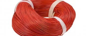
Storage of PV 3 in reels
Selection, nuances of choice
Before purchasing the wire necessary for the work, you need to calculate the required cross-section of the core taking into account the load. Careful calculation requires special knowledge and the ability to apply data from the tables “Rules for the construction of electrical installations” (PUE). For a non-professional, it is enough to know that a lighting network in a room requires 1.0 - 1.5 mm² of copper wire cross-section. Connection of sockets – 1.5 – 2.5 mm², electric boilers, stoves and air conditioners – 4.0. The entrance to a standard apartment is made with a cross-section of 6.0 mm². Having decided on the layout and wiring route for the facility, the total length of the wire of each required cross-section is calculated. A margin of size is needed, but the price range greatly depends on the diameter of the wire, so you should not include 6.0 mm² in the layout where 1.5 is enough.
Having completed the calculations, you need to start purchasing materials. The characteristics of the PV 3 wire comply with the requirements of GOST 6323-79, which standardize the material, the nominal cross-section of the core, and the thickness of the insulation. If there is no permanent, trustworthy supplier, the wire will be purchased randomly, wherever necessary. To protect your purchase from an dishonest seller, without trusting the markings, having a caliper is enough. The conductor diameter and insulation thickness are known from the technical specifications.
Important:
- Insulation. It can be single or double layer, in which case the first makes up at least 70% of the total thickness. The plastic should separate from the conductor easily enough without causing visible damage to the copper surface. The presence of dents, swellings and other irregularities is unacceptable.
- Lived. A fresh cut of the core will help you see the “correctness” of the material; you can find copper-plated aluminum at the price of copper. Irregularities, dark spots, non-copper color of the cut are a sign of poor quality copper. Real copper does not spring back when bent and can withstand at least 30 bends (high-quality aluminum will break after 8-10 times).
Table 7
| Number and nominal cross-section of cores, mm2 | Estimated weight of 1 km of wire, kg, brand | |
| PPV | APPV | |
| 2×0,75 | 21,9 | — |
| 2×1,0 | 29,5 | — |
| 2×1,2 | 34,3 | — |
| 2×1,5 | 39,8 | — |
| 2×2,0 | 52,5 | 27,5 |
| 2×2,5 | 62 | 31,5 |
| 2×3,0 | 76 | 36,5 |
| 2×4,0 | 92,4 | 43,2 |
| 2×5,0 | — | 49,2 |
| 2×6,0 | — | 58,0 |
| 3×0,75 | 33,2 | — |
| 3×1,0 | 44,6 | — |
| 3×1,2 | 51,1 | — |
| 3×1,5 | 60,0 | — |
| 3×2,0 | 79,0 | 41,5 |
| 3×2,5 | 94,0 | 48,0 |
| 3×3,0 | 112 | 53,5 |
| 3×4,0 | 137 | 64,0 |
| 3×5,0 | — | 74,0 |
| 3×6,0 | — | 86,5 |
Electrical insulation resistance of 1 km of wire is at least 106 Ohms; for wires with the HL index - at least 8-104 Ohms.
The electrical resistance of wire insulation, measured in water at a temperature of 70 ° C, is given in table. 8.
Check upon purchase
It is recommended to check the PV-3 cable very carefully before purchasing, since the market is flooded with a large number of fakes, characterized at best by an undersized cross-section, and at worst by a complete non-compliance with the stated requirements, primarily in terms of safety.
- It is always recommended to take products that are labeled with the wording GOST, and not TU. A cable made according to specifications is not formally considered a fake, but the fact is that each manufacturer determines the “technical conditions” for himself.
- A label should always be stuck on the bay, and alphanumeric markings should be applied to the insulation in a certain increment (about half a meter).
- Check the cross-section with a caliper you take with you.
- Request from the seller documents that the wire has passed the conductor resistance test, the insulation breakdown test, and the voltage test.
In addition, periodically during operation the cable must undergo “running tests”.
Supply of wires PV 1
You cannot ignore the conditions and requirements for delivery conditions. In addition, attention should be paid to the requirements for acceptance of the wire.
| According to GOST 6323 - 79, wire acceptance should be carried out according to certain rules. And the first item on this list is an external inspection of the wire. It must be marked accordingly, and the wire insulation must not be deformed. |
| Checking the wire cross-section | The next step is to check the design dimensions. It is quite possible to do this yourself. To do this, measure the cross-section of the wire, as well as the suitability of the insulation thickness. |
| At the same stage, they check how freely the insulation is separated from the conductor cores. According to GOST, insulation cut around the entire circumference at a distance of 13 cm from the edge should be removed without effort. |
| Test setup diagram | After this, high-voltage tests of the wire are carried out. We described them in the section on the electrical characteristics of the wire. |
| The next step is to check the electrical resistance of the wire. It should not exceed the standardized values shown in the photo above. However, for high-voltage tests and resistance determinations should be carried out on the same piece of wire. |
| After this, the packaging of the wire is checked and the presence of all the necessary symbols on its tag. The length of the wire, if any, the length of individual pieces of wire, the weight of the coil, the name of the manufacturer and the date of manufacture must be indicated on the coil. |
| Installation for testing wire bending resistance | The final test is the bending resistance test. To do this, take a roller with a diameter equal to 10 wire diameters and run the wire through it. If after this no deformation is detected, then the wire is accepted for use. |
Errors when using PV-3 cable
Minimum requirements for core cross-section
If the PV-3 wire is laid independently, some features and common mistakes should be taken into account. First of all, it is necessary to check the compliance of the cross-sections of the internal core and the solid cable. If the diameter is smaller, overloads and burnout cannot be avoided.
Do not allow the internal wires to come into contact. More often this happens when connecting two-key and three-key switches. In this case, there will be a simultaneous short circuit of two networks, and consequently – an interruption in operation, a lack of voltage, or a fire.
Soft single-core cable PV-3 is used in various conditions. The range of cross-sections and voltage levels allows for installation by external and internal methods. For complex systems, multi-core wires are used.
Main manufacturers
When purchasing cable and wire products, it is important to obtain specified parameters that can ensure the nominal operating conditions of the system. Otherwise, you may encounter the problem of insufficient cross-section or inappropriate climatic design, when the connected wire or cable begins to overheat and lead to a line burnout. Therefore, it is so important to purchase PV3 only from trusted manufacturers. Among the well-established factories, the following should be highlighted:
- TD Alliance Cable;
- Special cable;
- Moskabelmet;
- Interregional trade and industrial company.
If you are just going to buy PV3 wire, pay attention to the products of the above-mentioned factories. If you already have a brand of PV3 wire from some other manufacturer, and you want to use it in electrical work, it is better to check its cross-section and the quality of the insulation.