What you need to know about resistors?
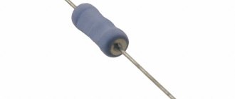
Resistor: A piece of material that resists the passage of electric current. Terminals are attached to both ends. That's all. What could be simpler?
It turns out that this is not at all simple. Temperature, capacitance, inductance and other parameters play a role in making a resistor a rather complex component. And there are many different ways to use it in circuits, but we will focus on the different types of fixed value resistors, how they are made and how they can be useful in different cases.
Let's start with the simplest and oldest.
Carbon composite in the turntable
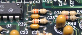
They are often called "old" resistors. They were widely used in the 1960s, but with the advent of other types of resistors and due to their relatively high cost, their use is now limited. They consist of a mixture of ceramic powder and carbon bonded with resin. Carbon conducts current well, and the more of it in the mixture, the less resistance. The wires are connected from the ends. They are covered with paint or plastic to serve as insulation, and resistance and tolerance are indicated by colored stripes.
The resistance of such resistors can be permanently changed by exposing them to high humidity, high voltage, or overheating. The tolerance is 5% or more. It's just a solid cylinder with good high frequency response. They also tolerate overheating well, despite their small size, and are still used in power supplies and welding controllers.
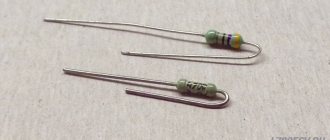
However, their age did not stop me from using a bag of these resistors that I bought at a thrift store for the purpose of making various resistors that I needed for my music project. player 555. The photo shows just my craft.
They are produced by applying a layer of pure carbon to a ceramic cylinder and then removing the carbon to form a spiral. The result is covered with silicon. The thickness of the layer and the width of the remaining carbon control the resistance, and the tolerance of such resistors can be from 2%, better than the previous ones. Thanks to pure carbon, resistance changes less with temperature.
The temperature coefficient of resistance of carbon film resistors ranges from 200 to 500 ppm/C - parts per million per degree Celsius. 200 ppm/C means that with each degree the resistance will not change by more than 200 ohms for each megohm of total resistance. As a percentage, this can be expressed as 0.02%/C. If the temperature changes by 80 C, at 200 ppm/C the resistor resistance will change by 1.6%, or 16 kOhm.
Such resistors are available in nominal values from 1 Ohm to 10 kOhm, with powers from 1/16 W to 5 W and can withstand voltages of several kilovolts. Commonly used in high voltage power supplies, X-ray machines, lasers and radar.
Metal film is made in a similar fashion to carbon, by placing a metal layer (often nickel-chromium) on ceramic, then cutting out a spiral. According to documentation from the manufacturer Vishay, after attaching the terminals, the spiral was previously processed by grinding, but now lasers are used for this. The result is varnished and marked with color coding or text.
The resistance of metal film resistors varies less than that of carbon film resistors. TCS is in the region of 50-100 ppm/C. 50 ppm/C is the same as 0.005%/C. Using a similar example to the above with a 1 MΩ resistor, a change in temperature of 80 C will result in a resistance change of 0.4%, or 4 kΩ, in the case of a 50 ppm/C resistor.
Their tolerance is less, about 0.1%. They also have good noise characteristics, low nonlinearity and good time stability, and are used for many purposes.
The case is similar to a metal film, only tin oxide with an admixture of antimony oxide is usually used. Such resistors behave better than carbon or metal films when it comes to voltage, overloads, surges and high temperatures. Resistors on carbon film operate up to 200 C, on metal - up to 250-300 C, and resistors on oxide film - up to 450 C. At the same time, their stability is very poor.
They are made by winding wires onto a plastic, ceramic or fiberglass cylinder. Since the wire can be cut quite accurately, their resistance value can be selected with great accuracy with a tolerance of no worse than 0.1%. To get a high resistance resistor, you need to use a very thin and long wire. The wire can be made thinner for less power or thicker for more power. It can be made from a wide range of metals and alloys, including nickel, chromium, copper, silver, chromium steel and tungsten.
They are developed with an eye to the ability to operate at high temperatures: tungsten ones can withstand temperatures up to 1700 C, silver ones - from 0 to 150 C. TCR for high-precision wirewound resistors is about 5 ppm/C. Resistors designed for high powers have a higher TCR.
They operate at powers from 0.5 W to 1000 W. Resistors of several hundred watts can be coated with high-temperature silicon or vitreous enamel. To increase heat dissipation, they can be equipped with an aluminum casing with plates that act as a radiator.
Types of winding
Since they are practically coils, they have inductance and capacitance, which makes them behave poorly at high frequencies. To reduce these effects, various clever winding schemes are used, such as bifilar winding, flat carrier winding, and Airton-Perry winding.
Bifilar winding has no induction, but high capacitance. Winding on a flat and thin medium brings the wires closer together and reduces induction. Airton-Perry winding, due to the fact that the wires go in different directions and are close to each other, reduces self-inductance and capacitance, since the voltage is the same at the intersection points.
Potentiometers are made using wirewound resistors due to their reliability. They are also used in circuit breakers and fuses. Their inductance can be increased and used as current sensors by measuring inductive reactance.
They use foil several microns thick, usually made of nickel-chromium with additions, located on a ceramic substrate. They are the most stable and accurate of all, even though they have been around since the 1960s. The required resistance is achieved by photo-etching the foil. They have no inductance, low capacitance, good stability and fast thermal stabilization. The tolerance can be within 0.001%.
TCS is 1 ppm/C. When the temperature changes by 80 C, the megaohm resistor will change its resistance by only 0.008% or 80 Ohms. The way in which such precision is achieved is interesting. As the temperature increases, the resistance also increases. But the resistor is made in such a way that an increase in temperature causes the foil to shrink, causing the resistance to drop. The overall effect is that the resistance remains almost unchanged.
Well suited for audio projects with high frequency currents. Also suitable for projects requiring high precision, such as electronic scales. Naturally used in areas where large temperature fluctuations are expected.
Mainly used for surface mounting. The film in thick-film resistors is 1000 times thicker than in thin-film resistors. These are the cheapest resistors, since thick film is cheaper.
Thin-film resistors are manufactured by ion sputtering of nickel-chromium onto an insulating substrate. Then photo-etching, abrasive or laser cleaning is applied. Thick film ones are made by stencil printing. The film is a mixture of binder, carrier and metal oxide. At the end of the process, abrasive or laser cleaning is applied.
The tolerance of thin-film resistors is at the level of 0.1%, and the TCR is from 5 to 50 ppm/C. For thick film, the tolerance is 1%, and TKS is 50 to 200 ppm/C. Thin film resistors are less noisy.
Thin film resistors are used where high precision is required. Thick film resistors can be used almost anywhere - some PCs can have up to 1000 thick film surface mount resistors.
There are other types of fixed value resistors, but in your resistor drawers you are most likely to see one listed.
Types of resistors according to the nature of resistance
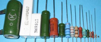
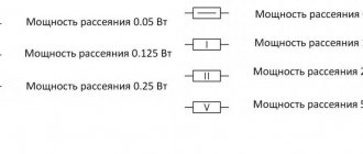
The main characteristic of resistors is the resistance itself, which is measured in “ohms”. The unit of measurement is designated as “Ohm” - after the name of the German physicist Georg Ohm. The second characteristic is power dissipation, measured in Watts (W). This is the power that the element can convert into heat without damaging its performance. Power dissipation is sometimes reflected on the diagram in the form of dashes on the “body” of the element (see the figure below on the right), but is precisely indicated in the specification. In principle, the power dissipation can be approximately determined by the dimensions of the element. The larger the case, the greater the power dissipation.
Designation of power dissipation of fixed resistors in the diagram
There are two types of resistors based on the nature of their resistance: constant and variable. Constants never change their resistance (ideally). Variables are changed, but forcibly. To do this, you need to move the slider, turn the knob or a special regulator. Variable resistors can be adjustable or tuning. In both types, the resistance can be changed within a certain range. Only adjustable ones usually have a wider range. They are the ones on the volume, frequency, etc. controls.
Variable resistor can often be seen in radios
There are also tuning resistors designed to fine-tune the specified parameters of radio and electronic devices during their release from production, during adjustment after installation or during the repair process. As a rule, they do not have a very wide range. On trimming models there is a small adjuster for a screwdriver (as a rule).
Definition
Measures of electrical resistance are called exemplary resistors if they are designed, manufactured for this purpose and have passed state verification. Divided into 2 groups:
- unambiguous measures of electrical resistance
(OMES) - resistance coils; - multivalued electrical resistance measures
(MMES) - resistance stores.
Range of resistance values reproduced using:
- resistance coils - from 10−4 to 1012 Ohms
- resistance stores - for one decade stage from 10−4 to 1012 Ohm

