Block diagram and designation on Ohmmeter diagrams
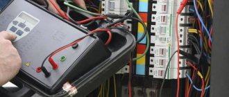
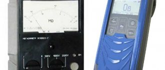
The Ohmmeter measuring device is structurally a dial or digital indicator with a battery or power source connected in series, as shown in the photograph.
All combined instruments - pointer testers and digital multimeters - have the function of measuring resistance.
In practice, a device that measures only resistance is used for special cases, for example, to measure insulation resistance at elevated voltages, ground loop resistance, or as a reference device for testing other low-precision ohmmeters.
On electrical measuring circuits, an ohmmeter is designated by the Greek letter omega enclosed in a circle, as shown in the photograph.
What is a multimeter
A multimeter or multitester is a compact, ergonomic and multifunctional device for measuring the basic parameters of an electrical network for any purpose. All multimeters allow you to measure current, voltage, resistance and even temperature with a certain accuracy using their probes.
Appearance of a typical dielectric plastic digital multimeter
There are two types of multimeters:
- Analogue, which display measurement results using mechanical display tools: arrows, bars and division values, showing the quantitative characteristics of the measured value;
- Digital. The most commonly used types of devices, the information is displayed through a built-in display, and all data is calculated digitally.
You may be interested in this Features of the SIP piercing clamp
Megaohmmeter GM3123 for use in industrial high voltage networks
Preparing an Ohmmeter for Measurements
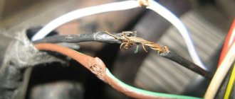
Repair of electrical wiring, electrical and radio engineering products consists of checking the integrity of the wires and searching for contact failure in their connections.
In some cases, the resistance must be equal to infinity, for example, insulation resistance. And in others it is zero, for example, the resistance of wires and their connections. And in some cases it is equal to a certain value, for example, the resistance of the filament of a light bulb or heating element.
Attention! In order to avoid failure of the Ohmmeter, it is allowed to measure the resistance of circuits only when they are completely de-energized.
You must unplug the plug from the socket or remove the batteries from the compartment. If the circuit contains electrolytic capacitors of larger capacity, then they must be discharged by shorting the capacitor terminals through a resistance of about 100 kOhm for a few seconds.
As with voltage measurements, before measuring resistance, it is necessary to prepare the device. To do this, you need to set the device switch to the position corresponding to the minimum measurement of the resistance value.
Before measurements, you should check the functionality of the device, since the batteries may be bad and the Ohmmeter may not work. To do this, you need to connect the ends of the probes together.
The tester's needle should be set exactly to the zero mark; if it is not set, then you can turn the "Set" knob. 0". If this does not work, you need to replace the batteries.
To test the continuity of electrical circuits, for example, when checking an incandescent light bulb, you can use a device whose batteries are dead and the needle does not set to 0, but reacts at least a little when the probes are connected. It will be possible to judge the integrity of the circuit by the fact that the arrow is deflected. Digital devices should also show zero readings, a deviation in tenths of ohms is possible due to the resistance of the probes and the transition resistance in the contacts connecting them to the terminals of the device.
When the ends of the probes are open, the tester arrow should be set to the point indicated on the scale ∞, and in digital instruments, the overload will blink or the number will be displayed 1
on the indicator on the left side.
The ohmmeter is ready for use. If you touch the ends of the probes to the conductor, then if it is intact, the device will show zero resistance, otherwise the readings will not change.
Expensive models of multimeters have a circuit continuity function with audio indication, indicated in the resistance measurement sector with a diode symbol. It is very convenient for testing low-impedance circuits, such as twisted pair cables for the Internet or household electrical wiring. If the wire is intact, then the continuity is accompanied by a sound signal, which eliminates the need to read readings from the multimeter indicator.
Examples from practice of measuring resistance of products
In theory, everything is usually clear, but in practice questions often arise that can best be answered by examples of checking the most common products with an ohmmeter.
Checking incandescent lamps
The incandescent light bulb in a lamp or car on-board devices has stopped shining, how can I find out the reason? The switch, electrical socket or wiring may be faulty. Using the tester, any incandescent lamp from a home lamp or car headlight, filament of fluorescent lamps and energy-saving lamps can be easily checked. To check, just set the device switch to the minimum resistance measurement position and touch the ends of the probes to the terminals of the light bulb base.
The resistance of the light bulb filament was 51 Ohms, which indicates its serviceability. If the thread were broken, the device would show infinite resistance. The resistance of a 220 V halogen light bulb with a power of 50 watts when illuminated is about 968 Ohms, and a 12 volt car light bulb with a power of 100 watts is about 1.44 Ohms.
It is worth noting that the resistance of an incandescent lamp filament in a cold state (when the light bulb is not lit) is several times less than in a warm state. This is due to the physical property of tungsten. Its resistance increases nonlinearly with heating. Therefore, incandescent lamps usually burn out the moment they are turned on.
Unfortunately, LED and energy-saving lamps cannot be checked with a multimeter without disassembling them, since the supply voltage from the base terminals is supplied to the driver diode bridge.
Using an online calculator, you can independently calculate the resistance of any incandescent light bulb or heating element, for example, a heating element, or an electric soldering iron.
| Online calculator for calculating the resistance value based on power consumption | |
| Supply voltage, V: | |
| Power, W: | |
Checking sound-reproducing headphones
It happens with headphones in one of the emitters, or in both at once, the sound is distorted, periodically disappears or is absent. There are two possible options: either the headphones or the device from which the signal is received are faulty. Using an ohmmeter, it is easy to find the cause of their breakdown and repair the headphones.
To check the headphones, you need to connect the ends of the probes to their connector. Typically, headphones are connected to the equipment using a 3.5 mm jack connector, shown in the photo.
One end of the probe touches the common terminal, and the other, in turn, touches the terminals of the right and left channels. The resistance should be the same and be about 40 ohms. Usually, the resistance is indicated in the passport for headphones.
If the resistance of the channels is very different, then there may be a short circuit or a broken wire in the wires. It is easy to verify this; just connect the ends of the probes to the terminals of the right and left channels. The resistance should be twice that of one earphone, that is, already 80 Ohms. In practice, the total resistance of series-connected emitters is measured.
If the resistance changes when the conductors move during measurements, it means that the wire is frayed in some place. Usually the wires fray where they exit the Jack or emitters.
To localize the location of the wire break, during measurements it is necessary to bend the wire locally, fixing the rest of it. Based on the instability of the ohmmeter readings, you will determine the location of the defect. If it’s a Jack, then you need to purchase a detachable connector, bite off the old one with a section of bad wire and solder the wire to the contacts of the new Jack.
If the break is located at the entrance to the headphones, then you need to disassemble them, remove the defective part of the wire, strip the ends and solder them to the same contacts to which the wires were soldered before. In the website article “How to solder with a soldering iron” you can learn about the art of soldering.
Measuring the resistor value (resistance)
Resistors (resistance) are widely used in electrical circuits. Therefore, when repairing electronic devices, it becomes necessary to check the serviceability of the resistor or determine its value.
On electrical diagrams, a resistor is designated as a rectangle, inside which its power is sometimes written in Roman numerals. I – one watt, II – two watts, IV – four watts, V – five watts.
You can check the resistor (resistance) and determine its value using a multimeter turned on in resistance measurement mode. In the resistance measurement mode sector, there are several switch positions. This is done in order to increase the accuracy of the measurement results.
For example, position 200 allows you to measure resistances up to 200 Ohms. 2k – up to 2000 Ohm (up to 2 kOhm). 2M – up to 2,000,000 Ohm. (up to 2 MOhm). The letter k after the numbers denotes the prefix kilo - the need to multiply the number by 1000, M stands for Mega, and the number needs to be multiplied by 1,000,000.
If the switch is set to position 2k, then when measuring a resistor with a nominal value of 300 kOhm, the device will show an overload. It is necessary to switch it to position 2M. In contrast to measuring voltage, it does not matter what position the switch is in; you can always switch it during the measurement process.
What is wire insulation resistance
Insulation resistance is one of the most important parameters of any cables and conductors. This is based on the fact that all wires are subject to external influences during their operation. In addition to external influence, there are also internal ones: the influence of the cores of one wire on each other, interaction through electromagnetic fields. All this, one way or another, leads to leaks.
Industrial megger for measuring large resistance values
That is why any electrical and non-electrical wires are created with insulation that protects the conductor from external influences. Popular insulating materials include rubber, polyvinyl chloride, oil, wood and paper. These materials are used based on the purpose of the cable. For example, wires buried underground are insulated with relatively thick dielectric tape, while telecommunications cables may be enclosed in a simple aluminum foil wrapper.
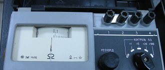
Old Soviet analog bench ohmmeter
Important! Insulation is the protection of cores from exposure to otherworldly factors, protection of cores from each other, from short circuits and from various leaks. Insulation resistance is the amount of resistance between the conductors of a wire or between one of the conductors and the insulating layer.
Any material ages and deteriorates over time, which leads to deterioration of its characteristics and a decrease in insulation resistance to direct or alternating current. The insulation resistance characteristic is indicated on the cable and is standardized in its GOST. It is determined in laboratory conditions at a temperature of 20 degrees.
Carrying out resistance measurements with a professional megohmmeter
Low-frequency communication cables have a minimum insulation resistance of 5 Gigaohms per kilometer, and coaxial cables, in turn, have a minimum insulation resistance of 10 Gigaohms per kilometer. Measurement and testing of resistance is carried out on a regular basis with a megohmmeter: at mobile communication installations - once every 6 months, at high-risk facilities - once every 12 months, at other facilities - once every three years.
You might be interested Features of press jaws
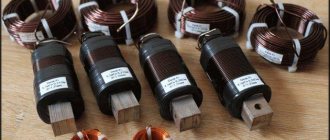
Resistor to increase the resistance of the electrical network
Online calculators for determining resistor values by color coding
Sometimes when checking a resistor, the ohmmeter shows some resistance, but if the resistor, as a result of overloads, has changed its resistance and it no longer corresponds to the marking, then such a resistor should not be used. Modern resistors are marked using colored rings. The most convenient way to determine the value of a resistor marked with colored rings is to use an online calculator.
Online calculator for determining the resistance of resistors marked with 4 colored rings
Online calculator for determining the resistance of resistors marked with 5 colored rings
Resistor resistance
All bodies capable of conducting electric current have resistance. But in the electrical circuit there is a special element responsible for creating resistance to the free flow of current. It's called a resistor. This name is derived from the Latin “resisto”, which means I resist.
There is nothing difficult in measuring the resistance value. Any multimeter can do this. But in the case of an analog device, problems arise due to the fact that in order to measure the resistance of the resistor, voltage must be present in the circuit. And mechanical testers, without a battery, operate without supplying electricity to the circuit. Therefore, you have to resort to using a resistive divider, supplying electric current to the circuit from an external source.
The disadvantage of most digital multimeters is their limited ability to record the value of resistors. The maximum value that an average tester can measure is 2000 kOhm. And this is clearly not enough to measure the operating parameters of resistors, which can produce a resistance 10 times greater than the capabilities of a multimeter. Therefore, you need to pay attention to the correspondence of the scale to the value of the resistor being tested.
To do this, you need to determine what the rating of the electrical product that creates resistance in the circuit is. Previously, this indicator was applied to the resistor body in the form of specific numbers. It was quite convenient. In those days, the elements were produced in large sizes and the inscription could easily be read, even with the naked eye.
Now the dimensions of the parts have become microscopic and it has become impossible to place, much less see, the written numbers. Therefore, the resistor values are indicated using color markings - in the form of four or five stripes. The meaning of the markings can be found in special tables. But it is not at all necessary to remember the values of the stripes on the body of the resistance element. It is much easier to use an online calculator.
To determine the value of the existing resistor, you need to select an element with 4 or 5 rings from the proposed options and put the appropriate mark. Then, by clicking on each strip, a color is selected from the proposed range. For some strips you are asked to choose from 8 colors, for others from 10, and for others from 12. After all the colors have been entered, the resistance value will appear at the bottom left.
The possible error of the resistor is also shown here. In the example given, the accuracy is 0.25%. This means that the deviation in resistance readings can be quite large. For some electronic devices this is unacceptable and it is necessary to know exactly what resistance the resistor produces. That's why they resort to using a multimeter.
To carry out measurements on the multimeter scale, you need to set a limit that is approximately suitable for the found value. The black wire of the tester is inserted into the “COM” or “–” socket, and the red wire into the “VΩmA”. The letter “Ω” means that resistance is measured through this socket.
Checking diodes with a multimeter or tester
Semiconductor diodes are widely used in electrical circuits to convert alternating current to direct current, and usually when repairing products, after an external inspection of the printed circuit board, the diodes are first checked. Diodes are made from germanium, silicon and other semiconductor materials.
In appearance, diodes come in different shapes, transparent and colored, in a metal, glass or plastic case. But they always have two conclusions and immediately catch the eye. The circuits mainly use rectifier diodes, zener diodes and LEDs.
The symbol for diodes in the diagram is an arrow pointing to a straight line segment. A diode is designated by the Latin letters VD, with the exception of LEDs, which are designated by the letters HL. Depending on the purpose of the diodes, additional elements are added to the designation scheme, which is reflected in the drawing above. Since there is more than one diode in a circuit, for convenience, a serial number is added after the letters VD or HL.
It is much easier to check a diode if you understand how it works. And the diode works like a nipple. When you inflate a ball, rubber boat or car tire, air enters it, but the nipple does not allow it back.
A diode works exactly the same. Only it passes in one direction not air, but electric current. Therefore, to check the diode, you need a direct current source, which can be a multimeter or a pointer tester, since they have a battery installed.
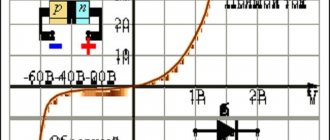
Above is a block diagram of the operation of a multimeter or tester in resistance measurement mode. As you can see, a DC voltage of a certain polarity is supplied to the terminals. It is customary to apply the plus to the red terminal, and the minus to the black. When you touch the diode terminals in such a way that the positive output of the device is on the anode terminal of the diode, and the negative output is on the cathode of the diode, then current will flow through the diode. If the probes are swapped, the diode will not pass current.
A diode can usually have three states - good, broken or broken. During a breakdown, the diode turns into a piece of wire; it will pass current no matter the order in which the probes touch. If there is a break, on the contrary, the current will never flow. Rarely, but there is another condition when the transition resistance changes. Such a malfunction can be determined by the readings on the display.
Using the above instructions, you can check rectifier diodes, zener diodes, Schottky diodes and LEDs, both with leads and in SMD version. Let's look at how to test diodes in practice.
First of all, it is necessary, observing the color coding, to insert the probes into the multimeter. Usually a black wire is inserted into COM, and a red wire into V/R/f (this is the positive terminal of the battery). Next, you need to set the operating mode switch to the dialing position (if there is such a measurement function), as in the photo, or to the 2kOm position. Turn on the device, close the ends of the probes and make sure it is working.
We’ll start the practice by checking the ancient germanium diode D7, this specimen is already 53 years old. Germanium-based diodes are now practically not produced due to the high cost of germanium itself and the low maximum operating temperature, only 80-100°C. But these diodes have the smallest voltage drop and noise level. They are highly valued by tube amplifier builders. In direct connection, the voltage drop across a germanium diode is only 0.129 V. The dial tester will show approximately 130 Ohms. When the polarity is changed, the multimeter shows 1, the dial tester will show infinity, which means a very high resistance. This diode is OK.
The procedure for checking silicon diodes is no different from checking those made of germanium. The cathode terminal is usually marked on the diode body; it can be a circle, line or dot. In direct connection, the drop across the diode junction is about 0.5 V. For powerful diodes, the drop voltage is less, and is about 0.4 V. Zener diodes and Schottky diodes are checked in the same way. The voltage drop of Schottky diodes is about 0.2 V.
For high-power LEDs, more than 2 V drops at the direct junction and the device can show 1. But here the LED itself is an indicator of serviceability. If, when turned on directly, you can see even the faintest glow of the LED, then it is working.
It should be noted that some types of high-power LEDs consist of a chain of several LEDs connected in series and this is not noticeable from the outside. Such LEDs sometimes have a voltage drop of up to 30 V, and they can only be tested from a power supply with an output voltage of more than 30 V and a current-limiting resistor connected in series with the LED.
Checking electrolytic capacitors
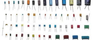
There are two main types of capacitors, simple and electrolytic. Simple capacitors can be included in the circuit in any way you like, but electrolytic capacitors can only be connected with polarity, otherwise the capacitor will fail.
On electrical diagrams, a capacitor is indicated by two parallel lines. When designating an electrolytic capacitor, its connection polarity must be indicated with a “+” sign.
Electrolytic capacitors have low reliability and are the most common cause of failure of electronic components of products. A swollen capacitor in the power supply of a computer or other device is not a rare sight.
Using a tester or multimeter in resistance measurement mode, you can successfully check the serviceability of electrolytic capacitors, or, as they say, ring. The capacitor must be removed from the printed circuit board and be sure to be discharged so as not to damage the device. To do this, you need to short-circuit its terminals with a metal object, such as tweezers. To test the capacitor, the switch on the device must be set to resistance measurement mode in the range of hundreds of kilo-ohms or mega-ohms.
Next, you need to touch the terminals of the capacitor with the probes. At the moment of contact, the instrument needle should sharply deviate along the scale and slowly return to the position of infinite resistance. The speed at which the needle deflects depends on the capacitance value of the capacitor. The larger the capacitor capacity, the slower the shooter will return to its place. A digital device (multimeter), when touching the probes to the terminals of the capacitor, will first show a small resistance, and then increasingly increasing up to hundreds of megohms.
If the behavior of the devices differs from that described above, for example, the resistance of the capacitor is zero Ohm or infinity, then in the first case there is a breakdown between the windings of the capacitor, and in the second, a break. Such a capacitor is faulty and cannot be used.