Module EGS002 (EG8010 + IR2110), which we will study well in practice
Yes, I understand. A little unexpected. To be honest, I didn’t expect it from myself. Everything described below is the result of a coincidence, nothing more.
One cold winter morning, as usual, I got up at six o’clock in the morning, washed my face, poured myself coffee and thought about the eternal. The eternal was gradually gathering in a heap in the head that had not yet woken up, but gradually lined up into an orderly series of plans for the coming day. Or at least for the next couple of hours.
You need to wake up your wife and children, get them ready, dress them and point them in the right direction, without being late. And then for some reason it suddenly got dark... Only the squeak of the UPS convinced me that this was not a brick on my head or a blow to the forehead. The electricity just went out.
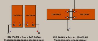
↑ Option two: you need a constant 12/24/36/48 V
The voltage depends on the transformer. As it is called on specialized forums - “BZhT” - Big Iron Transformer. The voltage required for conversion depends on its data.
BZhT can be used, for example, from an old UPS.
Oscillograms are shown for unipolar
mode. The modes are described in the datasheet. In unipolar mode, one half of the H-bridge works as a PWM, the other as a polarity switch.
In bipolar
mode, both arms thresh like PWM, but this requires a throttle for each half of the bridge and separate feedback for each half. Synchronous.
The EGS002 module is designed for unipolar mode, so I’m not considering others.
Well, now it’s time to try in practice what is so beautiful in theory.
Inverter: sine wave or modified sine wave?
One of the mandatory devices in your home's backup power supply system is an inverter. This device is designed to convert direct current from batteries into alternating current of 220 V with a frequency of 50 Hz, i.e. it provides similar mains power to electrical appliances in your home. Along the way, the inverter can solve additional problems. Such, for example, as disconnecting the load when the batteries are critically discharged. There are inverters that include a charge controller.
Please note that this device is required for backup power supply, because The main power supply is supplied by mains voltage 220 V AC with a frequency of 50 Hz. Since backup power supply is necessary when the main power supply is turned off, it must provide the same parameters as the network supply.
In the case of autonomous power supply, the inverter may or may not be used. This depends on your choice of power supply. If you use conventional household appliances in your home that are powered by 220 VAC, then you need an inverter. Some are supporters of using electrical appliances powered by 12 V, then they do without an inverter. Both cases have their advantages and disadvantages.
When choosing an inverter, first of all you need to decide what type of load is in your home. The fact is that inverters can be divided into two types.
The first is sine wave inverters, which provide a sinusoidal voltage waveform at the output. An inverter, called a pure sine wave inverter, will power all your home appliances. Its voltage waveform is no different from the voltage waveform of a centralized network.
The second is inverters that have a quasi-sinusoid (as if it were a sine wave) or a modified sine wave at the output. And these inverters must be used with caution. They can be used when among the consumers there are no devices with transformer inputs, electric motors and other devices that represent an inductive load.
What does this mean? This threatens with premature failure of your household appliances, because... when feeding them with a non-sinusoidal current, at best, there is a loss of power, and at worst, overheating. With electronic devices that monitor voltage quality, this can lead to failures.
What is the problem? Take the first type of inverter and don’t rack your brains. The problem is the difference in their costs. Sine wave inverters are 2, sometimes 2.5 times more expensive. Therefore, it makes sense to understand your consumers before choosing an inverter.
Boris Tsupilo
electric.info
↑ Practice according to Option 1
For the first option, we need to get a constant voltage of +400V.
How? Let's turn to motorists. Fragment excluded. The full version is available to patrons and full members of the community.
Controller UC3825. Push-pull. It is planned to use three pairs of P60NF06 field workers. From what I could buy on sale. To swing them, the driver is reinforced with a cascade of bipolars.
Overload protection is provided, and overheating and undervoltage protection is implemented as a separate module on IC1. There are two comparators. When overheating or when the voltage drops below 10.5 V, a voltage higher than 1 V enters the PWM controller protection circuit and it turns off.
Transformer
from a kilowatt UPS that fell in an unequal struggle with the electric company.
Primary:
4+4+4+4 turns with 0.8×4 wire. 4+4 is if you need 12 V. 4+4-4+4 is for 24 V.
Secondary:
147+10+10+10+20 with the same 0.8 mm wire. The taps are made in order to quickly change the number of turns to obtain 400 V. The choke after the bridge is pulled out of some power supply, it was used there as a DGS, the windings are connected in series to obtain the desired 2-2.2 mH. Better, of course, more.
The first version of DC/DC was made on a smaller trance, and at a load of 300 W it no longer pulled power higher than the specified one. And the number of turns indicated in the diagram simply did not fit on the frame. Therefore, the second version is described - revised and expanded.
Next is the inverter block itself.
Fragment excluded. The full version is available to patrons and full members of the community.
Provided two options for powering the low-voltage part - 12 and 24 V.
Choke L1 is a trans from a 400 W computer power supply. 80 turns of 0.8 mm wire. Almost full. Next, set the required inductance to 3.3 mN using spacers. Instead of a 2.2 µF capacitor, according to the datasheet, I installed 2? 1.5 µF x 630 V. Type SVV. What happened.
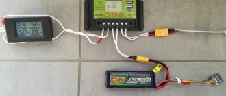
For the test, I used a freshly charged CSB 12 V 12 Ah battery for the first time. We need to test the 12/400 controller itself and then the inverter. Connecting.
In principle, there were no problems with the launch. You just need to adjust the output voltage. Everything turned out to be assembled correctly. The blue (!) indicator even shows something.
The display is very small, there is a battery plug right in front of it. And with a load in the form of a 220 V 40 W lamp, the current does not show - it needs to be adjusted.
But they didn’t deceive me - it’s really a sine!
The device has an interesting soft start. About 1-1.5 C. The voltage gradually “creeps” to normal. It reacts adequately to load changes, but after 250 W the inductor L1 of the 12/400 converter begins to squeal - it does not have enough capacity after the inductor. But this can be decided. But what to do with the current?
With a load of 250 W (40+60+150 W lamps) the battery lasts about 5 minutes! At the same time, the PWM radiator itself does not heat up above 30° - both according to the indicator and to the touch. The set of current protection resistors in the 12/400 converter heats up the most. That is, conversion for high powers, above 200 W, for a 12 V battery simply does not make any sense. Even if you have a car nearby. The measured current at a power of 160 W (40+60+60 W lamps) in a 12V circuit is 15-16 A. And the device seems to lie a lot at this current.
Well, okay, let's put this option aside for now and try another one - where BAT is used.
Reasons for the emergence of the project
In the last couple of years, the development of power converters accounts for about 90% of my orders, the main labor costs go mainly to software development and prototyping, circuit design + final board routing of the total costs is usually no more than 10-15%.
Here comes the understanding that the prototyping process, which includes software development, needs to be somehow shortened and optimized. As always, there are at least two ways out: buy a ready-made debug, for example, from Texas Instrumets or Infineon, but they are usually tailored for a specific task and cost from $500 to $5000, while there is no guarantee that there will be a similar order and this investment is highly likely to be simply won't pay off. The second option is to do it yourself, but doing it thoroughly is almost the same as launching a “+1 hardware revision,” which will result in additional expenses for the customer. If you don’t do it thoroughly, then, as usual, everything will be in snot and something will fall off somewhere, and so far the layout, components and deadlines. After some time, I noticed the most obvious solution. It is so simple and obvious that for a long time I wondered why TI or Infineon had not done this yet. Now I’ll tell you about my “enlightenment”.
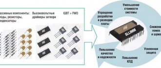
Let's look at some of the most popular power converter topologies:
Now look carefully again. I specifically drew it without any binding, just the key components, to make it clearer. What do these topologies have in common? The first thing that catches your eye is a number of general points:
- All topologies include basic components - capacitors, transistors and inductance (inductor or transformer). These are 3 pillars of power electronics;
- The transistors are connected everywhere equally and form a so-called “half bridge”. Almost all converter topologies are built from it;
- The option of switching on the half-bridge + capacitor combination does not change on all topologies. The type of inductance and options for connecting half-bridges change.
From this we can conclude that having a certain standard module in the form of a “half-bridge + capacitor” combination, you can build any converter by adding only the required inductor or transformer. Therefore, the obvious solution to simplify prototyping was to create a module like this:
↑ Practice on option 2. Large iron transformer
BZhT and a set of field workers in the amount of 8 pcs. were removed from the old IMV UPS at 700 W.
That's the torus there.
Two windings. The number of turns is unknown. What is known is that it ran on two batteries. When the primary is connected to a 220 V network, the secondary is 17 V. An H-bridge was used. Inverter circuit
it will be much easier.
Fragment excluded. The full version is available to patrons and full members of the community.
The inclusion is generally elementary.
But in terms of weight and size indicators, this is not a fact.
But the launch did not cause any problems either. Nothing shot or started smoking. Structurally, all power switches are located on radiators under an 80 mm fan.
The temperature sensor is attached to one of the radiators.
OK then. There are now two device options. You need to choose one. The criterion is efficiency. And it is even more important in this case than mass, power, etc. I load both converters in turn with 220 V 40 W bulbs. Two lamps in parallel - 80 W active power.
Does the 24V inverter come first? 400 V ? 220 V. The current in the 24 V circuit is 4.3 A. That is, to get 80 W at the output, we will spend 103 W from the batteries. Interesting.
Now the inverter is on BZhT. The current in the 24 V circuit is 3.6 A. And here it is already 86 W. Even more interesting! For some reason it seemed to me that it would be the other way around.
How does the piece of iron bear the load? I collected all the lamps that I had. This is a difficult task when there is no desk space. So: 150+150+40+40+60 = 440 W. I loaded both converters in turn with such a garland. The one with the 400 V converter blew out immediately - the trance squeak and PWM went out with the “undervoltage” error. But the BZhT started up easily and continued to work.
It turns out that the weak link is my 12/24?400V converter.
That is, to get at least 500 W, I need a larger trans, thicker wire, and so on. And most likely you need a ring. I don't have any other frames. Therefore, I will put it aside and continue with BAT.
I'll try to place the device in a UPS case from which the transformer was removed.
Everything fits. U-shaped brackets held two 7.2 Ah batteries inside the case. This is not enough for me, so the batteries will be outside.
Inclusion
After switching on, we get about 230V at the output, the output is of course not stabilized and will float 230V + -30V, it will work for tests, in another article we will finalize the layout as I decide to talk about P and PI regulators and their implementation.
Now you can enjoy the result of your work, and if necessary, cram everything into a box and even use it on the farm or in the country to provide yourself with light and other delights.
You probably noticed a delay between the “click”, that is, the supply of power to the Discovery and the turning on of the lamps - this is the time that the MK spent on initialization. This delay can be reduced if you write one digit to the register at a time, rather than splitting the register entry into a bunch of lines. I split it up purely for clarity. Although this is not scary, with HAL code the delay is 3 times longer and people somehow live with it))
Before I forget, the project sources:
- Schematic diagram - PDF
- BOM - Excel
- Gerber-files - RAR
It remains to see how the temperatures on the board are, and whether there are any particularly hot spots. 5-6A is certainly not enough, but if there is a through current or some other serious error, then this is enough to turn the board into a teapot:
As you can see, the hottest element is the dc/dc module for galvanic isolation, which is 2 W, it heats up to 34 degrees, and there’s also a shunt. The transistors themselves and the radiator are at ambient temperature after 30 minutes of converter operation))
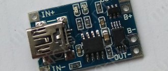
↑ Dual-channel charger
In general, I learned how to discharge batteries, now I need to learn how to charge them.
I know from experience operating a UPS with two batteries that charging batteries in series is not desirable. As a rule, one of the two fails earlier, resulting in a skewed capacity and other special effects. You need a charger to charge two batteries separately, with a limited charge current. I thought for a long time. But I decided to use the FSFA2100 I had already tested for this. Fragment excluded. The full version is available to patrons and full members of the community.
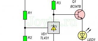
When fully charged, the current in the circuit becomes almost zero, and the battery full charge indicator lights up. At the same time, FSFA2100 can switch to Burst mode, thereby saving energy. I didn’t greatly complicate the system; I don’t see any practical point. A diode is installed in the positive wire of the power supply unit, which allows you to start the power supply unit with the battery connected. Otherwise, the protection allows you to do this only after disconnecting the battery and connecting it again after starting the power supply. An extra diode, but no problem. LED1 and LED2 – power indication, LED3 and LED4 – full charge indication. The threshold for turning on the LEDs 14.2-14.3 V is regulated by selecting R32 and R35.
The ideas used here were collected bit by bit on the Internet, so I do not claim authorship. It is better to select shunts according to the required current; I have 3 of them. 0.47 R each. So far it seems ok.
This is the resulting pothole.
The transformers are wound on cores similar to those I used in the power supply on FSFR/FSFA assemblies. Primary 40 turns Litz 0.07?80. The secondary 5+5 turns is also Litz 0.1×70. The inductance of the primary is slightly underestimated, about 450-470 µH, so there are fewer problems with starting on these trans.
During the work, it turned out that the radiators with the rectifier diodes got very hot, so I had to rack my brains about cooling. How to power the fan? Looking for 24 V? Make a stub? Connect it to only one battery? But then it will be more discharged. Damn, what am I doing? It’s too late to give up... And then I caught my eye on the duty power supply on FSDM0265RN, which I somehow used for experiments with other power supplies.
Fragment excluded. The full version is available to patrons and full members of the community.
A little modification and we got a power supply for powering the fan and relay. Factory transformer. The original output had two voltages - 5 V and 18 V. The winding for 5 V was wound in two wires, so without disassembling the transformer, I separated it and connected it in series. I slightly adjusted the output voltage. It turned out 12 V for the fan and 25 V for powering the relay (I had them at 24 V). Everything is within normal limits.
The purpose of the relay is discussed below, but here is a photo of the device.
This module was made after the charger, so I had to think a little about where and how to attach it.
Here it is on the left facing the main board.
How does an inverter based on an SPWM signal work?
The circuit of such an inverter is shown in the following figure.
As you can see, we used two N-type MOSFET transistors and a half bridge to drive the transformer in the circuit. To reduce unwanted noise and protect the MOSFETs, we used two 1N5819 diodes in parallel with the MOSFETs. To reduce possible unwanted pulses generated in the control section, we used 4.7 Ohm resistors connected in parallel with the 1N4148 diodes. And finally, transistors BD139 and BD 140 are connected in a push-pull circuit to drive the gates of MOSFET transistors because MOSFET transistors have a very high gate capacitance and require at least a voltage of 10V at their gate to operate correctly.
For a better understanding of the operating principles of the presented circuit, we have shown half of it in the following figure. Consider the case when the MOSFET transistor in it is open - in this situation, the current flows first through the transformer and then through the MOSFET transistor is shorted to ground, thus, a magnetic flux occurs in the same direction in which the current flows, so the transformer core transmits this magnetic flux to the second winding and thus at the output we get the positive half cycle of the sinusoidal signal.
In the next cycle, the current flows in the opposite direction and, therefore, the magnetic flux appears in the same direction, therefore the direction of the magnetic flux in the transformer core also changes (compared to the previous case considered).
That is, now we know that the direction of the magnetic flux in the transformer changes. Thus, by turning on and off both MOSFET transistors (they are inverted with respect to each other) and performing these switchings 50 times per second, we will form a changing magnetic field in the transformer core, therefore, the direction of the current in the secondary winding of the transformer will change in accordance with Farad's law. This is the basic principle of operation of the inverter.
Now in the following figure we will look at the complete circuit of a pure sine wave inverter based on Arduino board.
As you can see from the presented diagram, switching the operating cycles of the above presented inverter circuit will be carried out using two digital pins of the Arduino board.
Project design
For demonstration purposes, we have assembled a circuit of our inverter on a stripboard (Veroboard). A huge current will flow at the output of the circuit transformer, so in this place the connectors (connectors) must be used as thick as possible.
↑ What happened in total
Well, now a little about what happened in total.
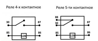
When there is no mains power, all relays are disabled.
In this position, you can turn on the inverter for battery operation. The inverter output is connected to the 220 V output socket. When there is mains power, then by turning on S1, we start the charger and service power supply. The relays are activated from it, one turns off the inverter start switch, so that in charging mode it does not accidentally start it from the batteries being charged, the other two relays turn off the output from the inverter, and transfer the output directly to the supply network.
The device charges and is transparent to the 220 V network. If the network is lost, the relays will turn off and you can switch to batteries on the go. Of course, this is not UPS and this will not happen so quickly, but there is no need for such an option.
Now you need to create a body from scrap materials. Otherwise it just doesn't make sense. On top there is a neat shelf for batteries.
And carrying handles. There was no desire to cut the original UPS case - there is thick metal and it’s not guaranteed that it will turn out as intended. And for now I’ll leave it in this form - during operation I may have to finish something off.
Well, what to do with the second version of the converter, the one with 400 V? Take it apart? I'll always have time. But the idea to try it in a different form came along the way. Everyone knows that our supply voltage is far from ideal. Usually this is a distortion of the shape and constant interference from refrigerators and switches. But who knows what else is there?
For switching power supplies, this is not a problem - they can be powered in any way and with anything. What if it's a torus? And also a power supply amplifier or DAC? Then the voltage curve from the network is lowered by the trance, maintaining its shape, and if there is also an admixture of constant, then any “gag” is also added. Then we have “artifacts” in the power supply, clicks, splashes, etc.
What if we run our network through a converter in double conversion mode? That is, get 400 V DC using a regular transformer, and then use a converter to get a pure sine wave without surges and other things! And at the same time get complete galvanic isolation from the network! Stabilized clean network.
Home audio equipment does not require large powers, so you can choose a small transformer. For example, I had a TS180-2 lying around.
Old, quite reliable. Why not try it? Then the diagram will look like this:
Fragment excluded. The full version is available to patrons and full members of the community.
You just need to strip the trans to the primary, and wind the secondary at 400 V and 16-18 V to power the driver and logic.
You can, of course, wind up the trans to the required voltage by collecting all the secondary ones in a pile (just 130 V), but I don’t want to do that. I want it right.
By the way, an autotransformer is not suitable here - after it there is a diode bridge and an H-bridge, where both outputs hang in the air relative to ground and power. Therefore, I would not take risks by making the power part on the body of the entire device - it is pointless and not safe.
Having rebuilt the board taking into account all the modifications, I put everything together and turn it on.
As usual, there were no problems with the launch. Just adjust the output voltage and current. During the work, it turned out that the load in the form of a 150 W light bulb is not a problem for this device. The hardest thing is for the transformer. It is the hottest element of the structure. The radiator is 38-40° all the time, I didn’t even wait for the cooling fan to come on.
Now we need to put it all in the box. All that was left from the previous design were the corners and textolite, and the body was quickly assembled from these remains. It’s unsightly, of course, but it’s not for the table or for an exhibition. The length of the sheet was a little short, so I left gaps at the top. This makes it easier to wear. In principle, you can close it later, but that’s it for now.
The load is my old “decoupling” on an unwinded TC180 and behind it a 150 W light bulb. So to speak, a test on a complex load.
On the back wall there is an input, an output, a fuse, a cooling fan and, most importantly, a switch. It breaks the ground circuit (third pin on the plug) between the input and output. I need this when I connect an oscilloscope through it and climb power circuits. For other tasks, this circuit can and sometimes needs to be closed.
What is sinusoidal PWM (SPWM)
SPWM stands for Sinusoidal Pulse Width Modulation and is translated as sinusoidal PWM (pulse width modulation). We previously looked at it in the sine and square pulse generator on Arduino.
As we know, in PWM we can change its duty cycle (busy factor, duty cycle), that is, the ratio of periods of activity (on-time) and inactivity (off-time). Thus, by changing the PWM duty cycle, we change the average pulse voltage. This is clearly shown in the following picture.
As can be seen from the picture presented, with a duty cycle (fill factor) of 100% we get an average output voltage of 5V, with a duty cycle of 50% we get an average output voltage of 2.5V, and with a duty cycle of 25% we get another 2 times less.
Sine wave voltage is an analog voltage that changes its amplitude over time, so we can reproduce the "behavior" of a sine wave by continuously changing the duty cycle of the PWM wave (signal), as shown in the following figure.
If you look at the diagrams presented below in this article, you will see that a capacitor is connected to the output of the transformer - it is precisely responsible for smoothing such an alternating current signal.
The input signal used will charge and discharge the capacitor according to the input signal and load. We will use a SPWM signal (sine wave PWM signal) of high frequency, it will have a very small duty cycle of 1% at first, this 1% will charge the capacitor just a little, a signal with a duty cycle of 5% will charge the capacitor a little more, a duty cycle of 10% will charge the capacitor is even larger and gradually we will reach a duty cycle of 100%, and after that we will reduce the duty cycle to 1%. This process will produce a very smooth curve, much like a sine wave. Thus, by providing the correct duty cycle at the input, we will get a good sine wave at the output.
↑ Summary
These are the kinds of things that can be triggered by a simple power outage.
This equipment worked on the floor at work for six hours, causing puzzled looks from those passing by. So the system is quite viable. After assembly I remembered one story. Several years ago, a former work colleague of mine received an interesting watch as a gift from the North American states. If you remember, these are the electromechanical Flip Clock watches shown in old films with an indication on flip cards.
So, not only are they 110 V, but the clock itself is synchronized from the mains at 60 Hz (our standard is 50 Hz). Naturally, they were seriously lagging behind in their work and were more like an element of the interior than a watch. Now this problem would be solved very simply. Another possible use for this device has been found.
But there are also three-phase versions! No, that's it, enough experiments for today!
Modified or pure sine wave. What to choose? | "Energy"
Now on many forums you can read about the great harm of a modified sine wave and suggestions to quickly run away as soon as this inscription appears in the visibility zone or in the description of the device. But with all the caution that must be observed when selecting an inverter for the devices with which you are going to use them, there is no need to panic in advance. It is better to carefully read the instructions or passport of the electrical appliance, and also find out as much information as possible about the specific brand of inverter that you are considering purchasing.
When can you safely use an inverter with a modified sine wave?
- if you are going to connect ordinary household appliances through it that do not have a motor in their device. Such inverters can successfully and without harm cope with recharging phones or laptops, connecting lighting fixtures and most kitchen appliances (except the refrigerator).
- it is allowed, but with caution, to be used with power tools and, for example, a vacuum cleaner. It all depends on the passport requirements for the voltage quality of the devices. In any case, connecting equipment with a motor through inverters with a modified sine wave will be imperceptible, but will not have a positive effect on its service life.
In what cases is it better not to think, but to definitely take an inverter only with a pure sine wave?
— it’s better not to skimp on protecting the gas boiler (and its circulation pump - a device with an engine)
— if the inverter’s task is to provide uninterrupted power supply to medical equipment. In addition to its own high cost, the health of patients depends on the reliable operation of the equipment.
- for other expensive and highly sensitive equipment. These often include audio systems, professional photographic equipment, as well as expensive server or telecommunications equipment.
www.stabilizator.spb.ru
Power converter circuits
A powerful inverter is mainly used to connect construction power tools during the construction of a summer house or hacienda. A low-power 500-watt voltage converter differs from a powerful 5,000-10,000-watt converter in the number of transformers and power transistors at the output. Therefore, the manufacturing complexity and price are almost the same; transistors are inexpensive. The power is optimally 3000 W, you can connect a drill, grinder and other tools.
I will show several inverter circuits from 12, 24, 36 to 220V. It is not recommended to install these in a passenger car; you can accidentally damage the electrics. The circuit design of DC AC converters 12 to 220 is simple, a master oscillator and a power section. The generator is made on the popular TL494 or analogues.
A large number of booster circuits from 12v to 220v for making with your own hands can be found at the link https://cxema.my1.ru/publ/istochniki_pitanija/preobrazovateli_naprjazhenija/101-4 In total there are about 140 circuits, half of them are boost converters with 12, 24 at 220V. Powers from 50 to 5000 W.
After assembly, you will need to adjust the entire circuit using an oscilloscope; it is advisable to have experience working with high-voltage circuits.
To assemble a powerful 2500 Watt inverter you will need 16 transistors and 4 suitable transformers. The cost of the product will be considerable, comparable to the cost of a similar radio designer. The advantage of such costs will be a pure sine output.
Sergey, hello! I have a question: I have a DC12->AC220 converter for 300W, I power my computer with it. Everything works fine for about 1-2 hours (consumption is approximately 120W). But when the converter lacks energy, it makes a wild squeak and immediately abruptly cuts off the output. At the same time, approximately 11.5 volts remain in the battery. The converter is Chinese, but in appearance it is quite good. The question itself is: why does this happen if there is still a lot of energy in the battery and how to improve this so that the converter sucks out at least half the energy. Ideally, it would also squeak a little before dying.