I inserted it, and lo and behold, everything worked. After this, it is supplied to the engine and causes the armature to spin in a certain direction.
Since the motor is of a reversible type, the voltage must be applied at least twice with a change in polarity. VOLTAGE STABILIZER BOARD ELIM-UKRAINE (universal)
The relays must be replaced or restored.
To do this, use a LATR to which a stabilizer is connected.
Actually, thanks to it, the different windings of the automatic transformer are switched. And also if the input voltage does not correspond to the range of threshold values, stabilization will not work. If this circuit is assembled, the KM contactor turns on and voltage is supplied to the output of the stabilizer. It is necessary to check sequentially all control units and elements of the wiring diagram.
To summarize the above, we note that the entire process of current normalization is accompanied by constant operation of the relay. *UNDER REPAIR* Control board. Because there was no scheme!
Hum and clicks
If the voltage regulator is humming a lot, you need to check that the supply voltage is not above or below the permissible ranges. The adjustment range in most cases lies within 100-250 Volts.
Attention! Even when in good condition, the autotransformer hums evenly and not too loudly. The servo drive also makes a hum when moving the brush assembly.
Relay voltage stabilizers make clicking noises during operation. This is normal, the relays (black rectangles in the picture below) switch taps from the windings to regulate the output voltage.
If the device makes a loud noise, this may indicate sparking of the brush in servo-driven models, problems with the relay, and poor contact of the internal wiring of the device.
Why use a stabilizer
The voltage stabilizer ensures automatic maintenance of the set load in the network
Single-phase and three-phase, electromechanical, electronic modifications of devices are designed to prevent voltage fluctuations and failures on the power line. The rectifier provides:
- constant power supply of household devices in conditions of voltage drop or increase;
- checking network parameters;
- interference filtering;
- protection against distortion and line fluctuations;
- stability of equipment power supply during long-term power surges;
- control of electrical wiring inputs and outputs;
- automatic maintenance of the set load in the network.
Stabilization devices are easy to use and long-lasting.
Servo motor repair
When the engine itself burns out, there are two options:
- Buying a new one and installing it.
- An attempt to restore an old engine.
The second option makes it possible to revive the engine on your own, however, not for a long time. For resuscitation, you need to disconnect the engine from the general circuit. After this, it must be connected to a powerful power source.
Your task is to supply current to its outputs with a constant voltage of 5 volts. The current should be between 90 and 160 mA. When such a current is supplied, every small particle of “garbage” burns out on the motor brushes.
Helpful advice: since the motor is of a reversible type, the polarity must be changed when applying voltage. This procedure is carried out twice.
After such actions, the engine will be able to work again, and the stabilizer will perform its main function. Next, according to a simple diagram, you can carry out the procedure for connecting the voltage stabilizer released.
This circuit involves connecting the input phase and neutral cables to the input phase and neutral terminals, respectively. The connection of the output wires is similar. A grounding wire must also be connected.
Stabilizer connection
Now let's move on to directly connecting the stabilizer itself. In order to get to its contacts, you may need to remove the outer cover.
Pass two cables (input and output) through the holes and clamp them under the terminals according to the following diagram:
Tighten the phase conductor of the stabilizer input cable to the INPUT terminal (Lin)
neutral wire (blue) to terminal N (Nin)
grounding conductor to the screw terminal marked “ground”
By the way, there may not be a separate ground terminal. Then screw this core into a screw on the device body itself.
There are models with terminal blocks for only 3 wires. In them only the phase returns back.
Zero for powering electrical appliances is taken from the common panel.
Now that you have applied voltage from the shield to the stabilizer, you need to return this voltage, but already stabilized, back to the common shield.
To do this, connect the cable - the output from the stabilizer.
its phase conductor to the OUTPUT terminal (Lout)
zero to N (Nout)
grounding conductor, in the same place as the grounding conductor from the input cable
Visually check the entire circuit again and close the lid.
Repair of relay stabilizer Resanta SPN-9000
The operating principle of relay stabilizers is based on stepwise regulation of the output voltage. Voltage stabilization in automatic mode is provided by a microprocessor. Switching of the autotransformer taps is carried out intermittently using powerful electrical relays controlled by transistor switches. The switching resolution of various stabilizers ranges from 5 to 20 V. Accordingly, the lower this value, the more stable the output voltage.
Let's consider two typical malfunctions that arise during the operation of electronic stabilizers, using the SPN-9000 as an example. Stabilization does not work when the input voltage decreases from ~220V to ~170V, or when it increases above ~220V. In both cases of absence of stabilization, the output voltage changes synchronously with the input. Sometimes, when the stabilizer is turned on, the plugs are knocked out, that is, short circuit protection is triggered. The main “disease” of electronic voltage stabilizers is burning and sticking of relay contacts.
Due to faulty relays, switches assembled on 2SD882 transistors manufactured by NEC fail. The relays (all five pieces) are replaced with new ones or restored. To do this, remove the covers from the relay, then remove the movable contact, free it from the spring and, using “zero” sandpaper, thoroughly clean all relay contacts (upper, movable and lower). Then they finally clean all the contacts with Galosh gasoline and reassemble the relay in the reverse order. Then they unsolder all five 2SD882 transistors and check the integrity of the transitions. If necessary, replace the transistors with new ones.
Just recently we had to repair a voltage stabilizer with an intermittent defect. Externally, this defect manifested itself as a chaotic display of the display segments turning on, accompanied by chaotic operation of the relay. This defect was codenamed “blizzard”. Occurs due to cold soldering of the XTA1 quartz resonator with an operating frequency of 8 MHz. It is clear that because of this, the U2 microcontroller will not work normally (the marking is covered with a label). It is necessary to take into account that the terminals of the problematic quartz resonator are poorly maintained. Therefore, it is best to desolder it, clean its pins with zero-grit sandpaper, then tin them thoroughly, solder them and install XTA1 in place.
When repairing the stabilizer, it is not superfluous to check all electrolytic capacitors on the controller board. The fact is that the manufacturer uses cheap JAKEC brand capacitors of extremely low quality. They measure not only their capacity, but also ESR. At this point, the repair of the voltage stabilizer can be considered complete. Then the voltage stabilizer is turned on and its performance is checked.
The machine does not turn on or crashes after the timer report
Most stabilizers do not enter operating mode immediately after switching on, but after a temporary delay. But after the report, the start-up timer does not occur, and the display indicator shows the letter N. An example of repairing a device with such a malfunction is discussed in the following videos:
For your information, the error code “H” indicates that the network voltage is too high and the protection has tripped. This is valid for devices, "Luxeon" and some others.
Interesting: the letter “H” means “High” or “High”, and L means “low”, “Low”. The resistor, the replacement of which you saw in the video, is responsible for the response thresholds for the upper and lower voltage levels. Due to incorrect resistance, the stabilization board cannot do its job and goes into protection.
Such symptoms or another malfunction code may be accompanied by the breakout of the circuit breaker supplying the stabilizer itself after the turn-on delay timer reports. In this case, the problem is solved by replacing the relays, which, if stuck, may result in increased current consumption.
Repair of electromechanical voltage stabilizers
The main problem with such stabilizers is overheating. It is absolutely necessary to carry out maintenance of the stabilizer once every 1-2 months, depending on operating conditions. And the repair of voltage stabilizers must begin with cleaning.
The problem of overheating manifests itself primarily due to the fact that the graphite brush, when moving along the surface of the transformer, inevitably wears out, and its particles, along with dust and other debris, remain on the contact track.
Now, when the brush continuously “crawls” over the surface, it begins to heat up more, spark, the debris burns and burns to the copper surface. In the future, this negative effect will increase like an avalanche, and if measures are not taken, it will reach irreversible limits, when cleaning will no longer help.
Of course, thermal sensors will save the situation - these are the first “bells”. If the stabilizer suddenly starts to turn off on its own, you should urgently call a specialist and clean the surface.
Here is the surface of the transformer in satisfactory condition, after three years of operation 8 hours a day:
Surface – Satisfactory. And this is after washing with alcohol.
And here is what indifference to the state of the stabilizer can lead to. This is the same stabilizer, a different phase:
Surface condition – Very bad
Even if you clean off this deposit, the cross-sectional area of the wire will irreversibly decrease by 20-30%, which will increase the heating of the wire and brush, and lead to the pessimistic processes described above:
The surface of the autotransformer is close. The wire insulation is burnt out, an interturn short circuit is possible. The epoxy also fell off due to overheating.
Only “zero” sandpaper will help here. You need to clean as you go with the brush, then rinse thoroughly with alcohol and wipe dry with a clean cloth.
Servomotor repair
Another breakdown is a malfunction of the servomotor when it stops moving the brush. The engine must be removed, cleaned, blown, and lubricated. Since a DC motor with brushes is used, you can try to idle it in both directions from a DC source with a voltage of about 5 V.
This way, without disassembling it, you can clean its brushes a little, because the engine rotates (or rather, turns) only at an angle of up to 180 degrees.
Electronic board repair
The engine may not turn over because there is no power coming to it. The power comes from the control board, from bipolar transistors. A pair of complementary transistors TIP41C and TIP42C is used, since the power supply to the circuit is bipolar. Transistors must be replaced in pairs, even if one is intact. And only one manufacturer.
Also in the same circuit, 10 Ohm resistors burn out (this is a consequence of the breakdown of transistors). When replacing resistors, nothing prevents you from increasing their power to 3 or 5 W, increasing operational reliability.
Well, replacing relays, transistors, limit switches and other small things - depending on the situation.
Power section repair
The power part includes autotransformers (I have already said enough about them). And also - a contactor and an input circuit breaker, whose contacts and terminals are lit. It must be periodically stretched, cleaned, and, if necessary, replaced.
Stabilizer stages
All stabilizer options have several stages of operation. The quality of the output voltage depends on their number. To understand the operation of the stages, consider an example. When a voltage of 220 volts of normal value is applied, the device runs it according to the circuit without changes. When the voltage drops to the limit values, the electronic key or relay connects the 1st stage, and a stable voltage of 220 volts appears at the output.
The subsequent voltage drop forces the stabilizer to switch to other stages, which will allow it to provide the necessary 220 volts. When there are no longer enough steps, the stabilizer will not be able to increase the voltage. The greater the number of stages, the wider its voltage adjustment interval.
Tips for connecting a voltage stabilizer:
- Before installation, always turn off the mains power at the electrical panel.
- Connect auxiliary protection of the device in the form of a circuit breaker and residual current device. This extends its service life. It is advisable to install the automation behind the meter, but in front of the protection.
- The electrical network for domestic use must have a grounding loop. Installation of the stabilizer without grounding is prohibited according to electrical safety rules.
- Installation of a stabilizing device in the house before the meter is prohibited. The best option for installing the stabilizer would be to use it according to the above scheme.
- It is forbidden to connect the stabilizer immediately after bringing it into the apartment from the cold. Condensation accumulates inside the case, which can severely damage the device when turned on and shorten its service life. Its installation on the street is also prohibited.
- A low power stabilizer of up to 5 kilowatts is connected directly to the outlet. This method is acceptable for garage conditions, country houses. Sometimes a portable stabilizer is installed separately for digital equipment, for example, on a computer, TV, etc.
For a three-phase 380 volt network, the stabilizer is connected to one device per phase, connecting them with a star circuit. This method achieves savings on the purchase of devices, as well as on its maintenance and repair, since a 3-phase device is much more expensive.
- After installation, you need to check the correctness of the connections and installation. To do this, connect automatic input devices in the switchboard. Crackling, buzzing, and sparking are not allowed. If there are no such signs, then the voltage stabilizer is connected correctly.
- It is not allowed to connect the stabilizer to a load exceeding the power of the device. Its power reserve must be at least 30%.
- The correct installation diagram is most often depicted on the device body. First you need to focus on this diagram. If there is no such scheme, then these recommendations are the best option. Popular models of stabilizers are connected in this way.
Every year it is necessary to check the reliability of the wiring connections in the terminal blocks and, if necessary, tighten them.
To increase the life of transistors and servomotor
Here's what Andrey writes:
I thought I could quickly solve the problem by installing a zener diode or a diode at worst, but the voltage levels are too low to make any difference. It is also possible to build something with a dead zone on transistors, but this is all a grandiose stucco on the board. Ideas swarmed in my head to insert a second op-amp and connect it to the break in the control circuit.
And then my father, looking over his shoulder, discovered in the diagram a completely unused (at least in the single-phase version) operational amplifier, already soldered on the board on legs 12, 13, 14 with output to pin 4XT2, which was simply hanging in the air. And then there were estimates of gain factors and feedback. As a result, this scheme was born. (picture based on one taken from the article).
Stabilizer circuit with response threshold
The threshold element is two back-to-back diodes connected in parallel. resistors R101 and R102 regulate the feedback and ultimately give the width of the dead zone. I settled on the 10k and 2.2k ratings which gives about 3V AC insensitivity. As soon as the voltage in the network changes to a larger value, one of the diodes opens and the electric motor is supplied not with a gradually increasing voltage, but immediately with a threshold, allowing the engine to immediately take a step. In addition, correction of the output voltage with a trimmer was required to set the output voltage. Well, with the second file I’m attaching what the printed circuit board looks like after modification.
Stabilizer printed circuit board after modification
Yes, in the original circuit, instead of a motor, I connected a small light bulb and a voltmeter. The tension gradually increases in either direction. In my circuit, the motor turns on when there is already a more serious voltage deviation. Moreover, if the voltage suddenly jumps in either direction, there will be no delays in operation.
Refinement affects accuracy, but in real life it does not matter much. The output voltage in my case has the right to vary +- 3 volts from the set nominal value. This is an inevitable price to pay for less nervousness of the servo. You can increase the gain of the first op-amp (blue text in the diagram) and get +- 1.5 volts.
There is one more moment. All experiments were carried out on a stabilizer in which the motor was replaced with a more expensive version with graphite brushes. It was not possible to check how it will spin with a standard motor.
Features of Resanta brand devices
It is not recommended to connect Resanta brand stabilizers to precision electronics, medical equipment, computers and LCD TVs. The reason for this is simple: in the event of a power surge in the network, the device’s protection will simply turn it off, and the output voltage may disappear for a short period of time, which can affect the operation of the equipment.
The advantages of Resanta devices include:
- high accuracy;
- performance;
- almost silent operation.
They are great for providing stable voltage in small factories and country houses - they can be connected to heating appliances, power tools, pumps, and automatic lines.
Relay damage
If at the stage of diagnosing the voltage stabilizer a faulty relay was identified, then the best thing that can be done is to replace it with a new one. This will be much more reliable. However, if a decision is made to repair the relay, then this should be done according to the following algorithm:
You need to test the relay coil with a multimeter. If it is broken, then it needs to be rewinded (here again you need an electric winder). If the coil is working properly, then the relay should be disassembled
This must be done extremely carefully so as not to damage its contents. When the device is disassembled, the contacts are inspected for melting, burning or darkening. If any, they should be removed with a needle file or a thin nail file.
Anything will do to remove carbon deposits and unevenness. Voltage is then applied to the relay coil to ensure that its normally open contacts move and connect. Reliability of operation must be checked with an ohmmeter. The contact resistance should be close to zero. Afterwards the relay is assembled. If possible, it is tested under load for a couple of hours and, if the tests are successfully completed, it is returned.
Causes of breakdowns
Most stabilizers have moving parts. Such components are constantly in motion and under the influence of electric current. They often experience significant heat and vibration. Over time, this mode of operation leads to increased wear and, as a result, failure.
Connecting a voltage stabilizer
In the case of a relay, its contacts may begin to heat up, which will cause them to burn and malfunction. Mechanical drives are constantly moving, so their elements can become loose, and the contact of the brush with the windings can deteriorate.
Incorrect installation can damage the stabilizer. It will simply overheat from lack of cooling air. After which the device will either generate an error signal and stop turning on, or will receive damage incompatible with operation.
Important! Do not block the ventilation holes of the stabilizer. There should be a distance of at least 100-150 mm between them and the nearest object
Temperature indicator
Repair of electromechanical stabilizer ASN-10000/1-EM
The electrical circuit diagram of the ASN-10000/1 EM stabilizer is shown in Fig. 1, the printed circuit board of the controller of this stabilizer is shown in Photo 1.
The operating principle of electromechanical stabilizers is based on smooth and precise regulation of the output voltage. The voltage change occurs due to the sliding of the electrical contact along the winding of the autotransformer using an electric drive. The stabilizer generates an error voltage, which is amplified by the operational amplifier and transistor output stage (power amplifier), and then it is supplied to the motor. Depending on the polarity of the error signal, the motor axis rotates in one direction or another. A slider is attached to the motor axis, which moves along the winding of the autotransformer, thereby normalizing the output voltage.
Let's consider one typical malfunction that occurs during the operation of electromechanical stabilizers, using the example of ASN-10000/1-EM and methods for eliminating it.
There is no output voltage stabilization.
The output voltage level can be different and remain unchanged. There is a smell of overheated components. The “Achilles heel” of electromechanical stabilizers is the reversible motor. The stabilizer controller constantly monitors the output voltage level. As a result, the engine rotor is in almost constant rotation, which leads to premature engine wear. After stopping the engine, the output stage of the motor control, assembled on the complementary pair of transistors Q1 TIP42C and Q2 TIP41C, may fail. In addition to these transistors, resistors R45 and R46, included in their collector circuit, burn out due to overheating. Their resistance is 10 Ohms and their power is 2 W. It would also be a good idea to check the linear stabilizer assembled on transistor Q3 TIP41C and zener diode DM4.
Of course, a worn-out engine requires replacement, but if replacement is not possible, you can try to restore it.
One of the simple ways to resuscitate a faulty engine is as follows: • disconnect the engine from the circuit; • apply a constant voltage of 5 V to its pins from a powerful power source, for example from an ATX computer power supply.
In this case, small particles of “garbage” are annealed on the motor brushes. Normal motor current consumption should be within 90...160 mA. Since the motor is reversible, voltage must be applied to the motor twice with polarity reversed. After these simple manipulations, engine performance is temporarily restored.
Components of three-phase Resanta ASN
Before moving on to repairing the voltage stabilizer, let’s first take a brief look at what our box consists of and how it works.
So, as I already said in the previous article about three-phase stabilizers, a three-phase stabilizer is three single-phase ones. The same is the case with Resanta asn-20000/3-em:
Three-phase electromechanical stabilizer - device
It can be seen that this stabilizer consists of three identical parts - three single-phase stabilizers, each of which stabilizes only its own phase. This applies to such common single-phase models as ASN 10000 1 em, etc.
That is, even if there is a significant imbalance in the phase voltages at the input, the output for all phases will be 220 V + -3%. You can read more about the parameters of such stabilizers in the instructions, which can be downloaded at the end of the article.
And if the phase imbalance occurred as a result of a zero break, you can read about the consequences of this here. A three-phase stabilizer will correct the situation to a certain extent, and if it fails, it will turn off and save the consumer.
Autotransformer
The heart of an electromechanical transformer is a step-up autotransformer. This “heart” beats in time with the change in voltage at the input of the stabilizer, trying to equalize it to normal.
Step-up autotransformer - the heart of the electromechanical stabilizer
Why is a step-up autotransformer used rather than a step-down autotransformer? Because stabilizers most often have to deal with reduced input voltage. But this does not mean, of course, that it cannot reduce the overestimated input voltage. However, I will not describe the principles of operation of the autotransformer here.
Let's look at the stabilizer device in the following photo:
Stabilizer device with explanations
The first thing you need to understand is that an autotransformer consists of two equal parts connected in parallel to increase power. Accordingly, there are two windings, two brushes ride on them (the brush is not visible in the photo, it is indicated by an arrow).
Since the brush is a contact, and a rather poor one at that, it gets hot. This is normal, but a radiator is provided to cool it. A temperature sensor is installed in the brush radiator, which, when the permissible temperature is exceeded (105°C), opens the control circuit and disconnects the load from the stabilizer output.
The motor moves brushes along the surface of the winding, adjusting the voltage. At the end of the brush stroke, corresponding to the lowest voltage (140 V), limit switches are installed to stop the motor. This is the most difficult operating mode, since the output power of the stabilizer drops. If the voltage drops further, the autotransformer can no longer cope, and the entire stabilizer turns off. This occurs by opening the KL relay contacts (see circuit diagram below).
A temperature sensor is attached (glued) to the transformer body, which, when overheated above 125 °C, opens the control circuit, protecting it from further thermal destruction.
Both types of sensors are self-healing. That is, when it cools down, the control circuit is assembled, and the stabilizer is ready for use again.
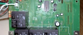
Electronic board
What makes the autotransformer motor move? This is an electronic circuit that measures the input phase voltage and outputs voltage to a servo motor, which moves the autotransformer brush, changing the output voltage to the desired level:
Electronic control board
The above photo shows the consequences of eliminating a common malfunction - breakdown of bipolar power transistors through which the engine is controlled. Along with them, resistors also burn out, which initially had a power of 2W, but were replaced by 5W. But for malfunctions and repairs - at the end of the article.
Control circuit starter
This starter is necessary to protect (turn off) the stabilizer and load in case of unavailability, malfunction or overheating.
Control circuit starter
Let's take a closer look at its operation when analyzing the electrical circuit diagram.
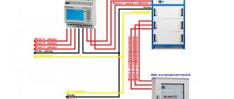
Electrical diagram of a three-phase voltage stabilizer Resanta
Let's consider the circuit of a single-phase electromechanical stabilizer Resanta ASN - 10000/1-EM. Let's take this circuit, because, as I said, three single-phase ones are one three-phase stabilizer.
The diagram, as usual, can be zoomed in and then enlarged to 100% by clicking on the arrows in the lower right corner of the image. Then right-click, Save Image As... etc.
How to print such a large diagram - be sure to read this article.
I downloaded the diagram on the Internet, author, respond!
Electrical diagram of voltage stabilizer Resanta-ASN-10000-1-em
For ease of perception, I have marked the main structural parts on the diagram.
Typically, the voltage stabilizer uses ha17324a - this is an operational amplifier chip, it compares the voltages and outputs a signal to transistors TIP41 and TIP42, which supply power to the autotransformer motor.
I will not fully consider the operation of electronics; if you are interested, ask questions in the comments.
Now - how does this circuit differ from the circuit of a three-phase stabilizer:
The main difference is in the control circuit. In the single-phase version (in the diagram) it can be seen that the control circuit for powering the KM starter is assembled as follows: Neutral – On-delay relay KL – Thermal relay 1 transformer (125°C) – Thermal relay 2 transformer (125°C) – Thermal relay 1 brush (105 °C) – Brush thermal relay 2 (105°C). Total – 5 contacts. If this circuit is assembled, the KM contactor turns on and voltage is supplied to the output of the stabilizer.
In the three-phase version, in order for the stabilizer to start, 15 (!) conditions must be met - this is exactly how many contacts must be closed in order for the KM contactor to turn on.
During normal operation, when the stabilizer is turned on, you can hear how the CC is assembled - after about 10 seconds there is a click (on one of the electronic boards), then another one, and the third click starts the contactor and the entire stabilizer.
What is a control circuit, its difference from emergency and thermal circuits, and why the repair of any serious automation must begin with checking the control circuit - it is described in detail in my other article, I highly recommend it if you have read this far)
The second is the absence of a cooling fan; in this case, the cooling is natural.
Third, there is no bypass; its implementation will require the use of a three-pole contactor with normally closed contacts (or two conventional contactors), this is expensive, so the manufacturer did without it.
I also write about this problem in an article about connecting a gasoline generator to a house via an automatic transfer switch.
Well, then - the logical differences: Three current transformers, three ammeters, etc.. Let’s not pour water, but let’s move on to what I intended this article for - repairing an electromechanical voltage stabilizer with my own hands.
Control board repair
Diagnostics and repair of the control board require at least minimal knowledge in electronics. You need to make sure that all nodes in the circuit are receiving power. Check the voltage at the collectors of the output transistors and at the operational amplifier. The ha17324a chip in a voltage stabilizer is the most common. This is the op-amp described above, on which the power should be checked. Then the board is examined for the presence of swollen or leaking capacitors (electrolytes), broken diodes, broken resistors, burnt fuses and simply fallen off parts. The places where components are soldered are inspected especially carefully, as cracks are possible there. Large parts need to be moved by hand to make sure they are securely soldered to the board. These problems are the most common cause of failure of any electronic device; they should be looked for first.
Chip HA17324A
Additional Information. To accurately check the transistor, it should be removed from the board. Otherwise, incorrect results may occur.
For a person who has knowledge and experience in repairing electrical and electronics, setting up a voltage stabilizer will not be particularly difficult. Such work is considered justified in most cases. Buying a new device will cost many times more than purchasing parts to repair it.
Repair of relay voltage stabilizers
In relay stabilizers, electromagnetic relays have the least reliability. The flow of large currents through the contacts causes them to burn or even sinter. The latter is dangerous because it can cause a short circuit of part of the windings of the autotransformer.
Resanta voltage stabilizers or similar ones have five relays on the board that switch parts of the autotransformer windings according to a certain algorithm. Predominant fluctuations in the input voltage around one value lead to the fact that only part of the relay, one or two, are constantly in operation. Therefore, they are the ones who fail in the first place.
Finding a faulty element is made difficult by the fact that small-sized relays of low- and medium-power stabilizers have an opaque, non-separable housing. It is sometimes possible to identify a faulty relay by lightly tapping each relay housing with an insulated screwdriver handle. Under mechanical stress, the resistance between the burnt contacts can be restored, and the sintered contacts can open. Found relays must be changed without fail.
Relay board
Powerful devices may have relays in a transparent case, through which the operation of the contact groups is visually observed. In addition, the housing is dismountable for easy cleaning. Burnt contacts can be cleaned up with fine-grained sandpaper. The grain size should be even smaller than when cleaning the windings of electromechanical stabilizers.
Relay in transparent case
If a visual inspection does not reveal any damage, the relay can be removed from the board and the contacts can be tested using an ohmmeter. The location and numbering of the contacts are given on one side of the relay housing. The device should show an infinitely large resistance between normally open contacts, and close to zero resistance between closed contacts. By applying a constant voltage of 12 V to the control winding, the contacts ring again. Now those that were open should close and vice versa.
Important! Relays have powerful leads and require the use of an appropriate soldering iron for soldering. Do not overheat the printed circuit conductors
The principle of operation of the stabilizer
Since only relays are capable of clicking in the stabilizer, it means that it is made according to a relay circuit. Each relay stabilizer has an autotransformer in its structure that increases or decreases the voltage based on the ratio of the turns of the windings. When the voltage value approaches the upper limit of the range, the device circuit switches to the autotransformer winding with a lower voltage value, and, as a result, the output voltage becomes lower. In the same way, this works in the opposite direction: when the voltage in the network deviates towards the lower threshold, the stabilizing device switches to the step-up winding of the autotransformer.
The process of switching the transformer windings is supervised by a special device - the stabilizer controller, and the switching is made through a set of power relays. It is these relays that, at the moment of connection, produce the very clicks that the user hears.
A standard stabilizer can contain from four to seven power relays. And the more voltage surges in the power supply network, the more often switching occurs and clicks are heard. Also, at these moments, the light may blink and highly sensitive equipment may turn off.
There may be several reasons for regular stabilizer clicks:
- Failure of one of the power relays. Since the relay has a limited switching resource, when it is exhausted, the contacts begin to burn and the contact resistance increases. This provokes a large voltage drop at the output of the stabilizer, and the greater the load, the greater the drawdown. Trying to correct the situation, the controller begins to switch to the next stage, where the voltage is actually higher and the controller has to switch again to the previous relay. In this way, a vicious circle of switching and clicking is formed.
- Poor condition of the electrical supply network. These could be poor contacts, the presence of many twists, or a long line with a small number of conductor sections. When trying to connect a load through a stabilization device, the mains voltage decreases at the moment of connection. Having detected this moment, the stabilizer begins to try to increase it by switching to a higher voltage autotransformer winding. But at the moment of connection, the consumer power circuit is disconnected for seconds and the mains voltage returns to its normal level. Noticing this, the stabilization device switches again to the previous level of the circuit. This creates an endless cycle of switching between power relays.
- There is a problem with the control circuit (controller). The problem is individual due to differences between the circuits for each individual stabilizer. However, typically the controller must have some offset to avoid constant tripping within certain voltage values.
Continuous clicking can lead to rapid failure of the device. Since relays are not designed for this mode of operation, the contacts can quickly burn or stick. Sticking will either lead to the burnout of the fuse at the input or to the fact that increased voltage will be supplied to the output of the stabilizer, which can lead to the failure of consumer devices.
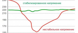
Graphic display of the main operating modes of voltage stabilizers
In one of the previous articles, voltages were described and also brought to the network with your own hands. This material outlines the main problems with voltage stabilization devices and the possibility of repairing them yourself.
It must be remembered that a stabilizer of any type is a complex electrical or electromechanical device with many components inside, therefore, in order to repair it with your own hands, you must have a fairly deep knowledge of radio engineering. Repairing a voltage stabilizer also requires the availability of appropriate measuring equipment and tools.
Complex stabilizer device
Principle of operation
The structural structure of the Resanta voltage stabilizer is as follows:
- automatic type transformer;
- the electronic unit;
- voltmeter;
- a control element that is responsible for starting and turning off certain windings.
This manufacturer produces many different types of stabilizers, so these winding connections will also vary. We will talk about all these nuances a little later, while considering the repair procedure.
In this design, the decisive factor is the electronic unit, which exercises general control of the entire system of the unit. He is responsible for the operation of the voltmeter, and also receives information about the power of the input voltage. Then, the block compares the obtained values with the optimal ones, determining the next action, i.e. whether it is necessary to add a few volts or, on the contrary, to subtract a certain amount.
Next, along the chain, is the determination of the necessary windings - which ones need to be started and which ones need to be turned off. Then, the electronic unit carries out one of these actions, after which all electrical appliances in the apartment receive a stable current.
Of course, the stabilization process itself may be slightly different, depending on the type of device being manufactured.
This difference applies to the types of windings, as well as the methods of starting and stopping them. Today, the Resanta company produces two types of these stabilizers:
- Electromechanical type.
- Relay.
Accordingly, their repair will be somewhat different.
Features of the electromechanical stabilizer
Let's start our consideration with electromechanical type stabilizers. Its design contains a servo drive, which starts and turns off the windings in the device.
The servo drive itself consists of a motor on which an electrical contact (brush) is located. When the armature of this motor moves, this brush also rotates, constantly contacting the copper windings. The width of this brush allows for complete coverage of the entire winding, which allows the phase not to disappear.
In order for the brush to move in a given direction with the desired characteristics, an error voltage occurs in the device. Then, this voltage value increases. It is then transmitted to the engine, which causes the armature to rotate in the optimal direction. Accordingly, the brush also moves, like the anchor, in the same specified direction. In this case, direct contact is made with the windings.
The error voltage value will be proportional to the value generated by the difference between the actual volt value at the input and the value that should be there. This signal can have one of two polarities, each of which specifies a specific direction of movement. Below is a diagram of such a voltage stabilizer:
Regardless of the specific model, the structure of this voltage stabilizer will be almost the same. They differ from each other in different power values and individual circuit elements.
Features of the relay stabilizer
All relay stabilizers equalize current values by jumps. This is explained by the fact that the relay starts or turns off the turns located on the second winding. An electromechanical stabilizer performs this process more smoothly than a relay one.
Relay units from Resant connect turns until they find the right one. All these turns are conventionally divided into subgroups, and from each turn there is a terminal, which receives current when the device starts up.
The diagram of all relay stabilizers of this brand shows that its design contains about four relay elements. In some cases, this number can be equal to five (SPN models).
In the case of relay stabilizers, it is the relay that is the most vulnerable point of the entire device. This is due to the fact that it is in constant operating mode, which significantly increases the risk of failure.
Basic faults
Having examined the operating principles of both types of voltage stabilizers, we can conclude that it is their main components that are the most frequently broken components of the system. We are talking about a servo drive in electromechanical devices, as well as relays in relay devices.
In the first case, the constant movement of the servo drive leads to periodic friction of the turns of the coil and brush, which leads to excessive overheating of these components. This also causes severe wear and sparks from the copper wires.
It is also necessary to keep in mind the fact that the current value in the network periodically changes, which provokes a similar change in the movement of the servo drive. Such unstable operation can lead to failure of this device.
Repair of one of the faults is demonstrated in the video
Prices for repair of voltage stabilizers
| Name of repair service | Cost, rub. |
| Service engineer visit | from 1500 |
| Diagnostics of stabilizers for damage | from 400 |
| Delivery of equipment to a service center within the Moscow Ring Road | 300 |
| Delivery of equipment from the service center within the Moscow Ring Road | from 400 |
| Delivery of equipment to a service center outside the Moscow Ring Road | 20r/km |
| Delivery of equipment from the service center outside the Moscow Ring Road | 20r/km |
| Transformer replacement | from 1500 |
| Replacing Terminal Blocks | from 500 |
| Replacing the cooling fan | from 200 |
| Replacing the circuit breaker | from 100 |
| Control board repair | from 400 |
| Replacing a digital meter | from 500 |
| Electric motor repair | from 600 |
Need advice on stabilizer repair? Call us at number.
Types of stabilizers, differences in their design
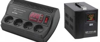
Relay voltage stabilizer
The standard stabilizer is a transformer with a control board, a system for selecting the number of turns on the winding, measuring, indicator and switching mechanisms.
Depending on the design, there are several types of devices:
- Step, or relay. They are manufactured in the form of a power transformer with winding outputs. The network parameters are regulated by a sensor that switches the relay during voltage surges. Some power modifications place a load on a terminal whose voltage is different.
- Servo-driven or electromechanical. The output network is adjusted manually. They operate on the principle of changing the transformation ratio by means of a brush connected to the output electrode. They differ in the accuracy of maintaining the load - 2-3%.
- Two-stage. The inverter device converts the alternating current output into direct current, and then creates alternating voltage. It is produced without a power transformer, can operate idle, smoothly adjusts the intensity at the input, suppresses oscillations and interference.
- Ferroresonant. Maintain output voltage accuracy using magnetic saturation. A special feature of the devices is transformer windings on magnetic cores with different cross sections.