Due to unstable voltage in houses and apartments, people are forced to install voltage stabilizers (hereinafter referred to as SV) to power the entire home or to operate a specific device. As with any other type of electrical appliance, sometimes a situation arises when the voltage stabilizer does not work (broken). Internal faults in most cases are associated with power circuits: relays, triacs, servo drive control unit, etc. Therefore, before you begin to analyze the malfunction and the cause of its occurrence, you need to understand what type of stabilizer you have failed. In this article, we will look at what types of voltage stabilizer malfunctions there are, why they occur, and how to fix them yourself (if possible).
Hum and clicks
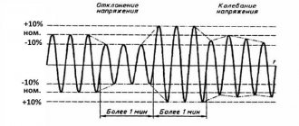
If the voltage regulator is humming a lot, you need to check that the supply voltage is not above or below the permissible ranges. The adjustment range in most cases lies within 100-250 Volts.
Attention! Even when in good condition, the autotransformer hums evenly and not too loudly. The servo drive also makes a hum when the brush assembly moves. Relay voltage stabilizers make clicking noises during operation. This is normal, the relays (black rectangles in the picture below) switch taps from the windings to regulate the output voltage.
If the device makes a loud noise, this may indicate sparking of the brush in servo-driven models, problems with the relay, and poor contact of the internal wiring of the device.
Unnatural noise and clicking
If an unnaturally loud noise or clicking noise occurs during operation, it is necessary to determine the supply voltage.
It must be within the limits specified in the instructions for a specific stabilizer. For most devices, the operating limits are 100-250 Volts.
It is worth noting that slight noise during operation is typical for all stabilizers.
This is how the brush assembly moves. Clicks are also natural; they are produced by voltage relay devices.
For this reason, it is important to be able to distinguish normal, background noise from a malfunction. If the clicks sound more often and louder than usual, then the reason may be sparking from the brush.
It is also possible that problems have arisen in the relay itself or the internal wiring contact has become loose.
Shuts down under load
The voltage stabilizer does not support the load - this problem happens for a number of reasons. The first among them is increased load (consumer power). If you have not changed the connected devices, then the problem is in the stabilizer. If it does not turn off instantly, but after some time of operation, then this may be due to overheating or interturn short circuits of the autotransformer.
What to do: disassemble the device and carry out an external inspection of the windings of the autotransformer; if it is not too dusty, then check for signs of local overheating. If there is a lot of dust, clean it out
If there are signs of overheating and burning, the insulation of the windings is damaged. This is an interturn short circuit, then how to repair the stabilizer in this case? It is necessary to rewind or replace the autotransformer with one of the same or greater power. But the cost of such repairs can be comparable to purchasing a new voltage stabilizer.
Important! In servo-drive models, a number of malfunctions can be caused by brush wear and contamination of live parts with graphite shavings. During operation, the brush wears off, covering the autotransformer with graphite. Because of this, short circuits between current collectors and sections of turns and overheating can occur. In this case, you need to sweep away the graphite and clean it between turns. Make sure that the windings are laid evenly and there are no breaks. Clean the contact surface with a regular office eraser until it shines, especially the most used sector.
Shutdown under load
A common reason for going to a service center is when the stabilizer turns off when the load increases. There may be several reasons for such a failure.
More often than others, there is the banal impotence of the stabilizer in the face of the imposed loads. In other words, the device is not designed for the supplied voltage. Another possible cause is overheating of the device or an internal short circuit.
A solution to the problem is to completely disassemble the stabilizer. Next, you should inspect the internal structure for heavy dust. If present, the device should be thoroughly cleaned.
It is also worth paying attention to the temperature of the indoor unit. If there are traces of burning, the insulation of the windings should be examined. The solution to the problem is to replace the transformer. If the damage is not severe, then rewinding may help.
One of the subtypes of voltage stabilizer is the servo type. It is characterized by frequent problems with the graphite layer of the brush.
So, over time it wears off and the material gets onto the surface of the transformer. Graphite can cause short circuits and overheating. In this case, experts recommend removing the chips and cleaning.
After this, it is worth cleaning the surface of the stationery erasers.
There is no 220 Volt output
The malfunction manifests itself in the fact that the stabilizer does not produce a voltage of 220 Volts. This does not necessarily indicate internal problems, the reason may be the mains voltage - it is too low, and the device simply does not pull. If the power is in the operating range of the stabilizer, then we will proceed with the repair.
What to do: in servo-driven models, failure can be caused by wear of the brush mechanism or the servo drive itself. It may not reach the end of the winding or the brush may not be in contact with its corresponding sector. In the simplest case, it may simply be contaminated with graphite. To repair it, you need to clean the surface of the contacts to a metallic shine. Sometimes you need to replace the brush.
Interesting! It also happens that due to contamination of the working sector of the brush assembly with graphite, the voltage often does not rise above a certain value.
In relay MVs, this most often indicates that one or more electromagnetic relays or their control cascade is faulty. It is usually built on a transistor. Relays can have different coil voltages, often 12 volts.
What to do: to check, apply voltage to the coil and ring the power contacts. They should close and open, the relay clicks. If this does not happen, either the contacts have stuck (more often), or the relay coil has burned out (less often). If the relay is working properly, check the transistor; it should not be broken, and the emitter-base and collector-base junctions should ring in one direction, like a diode. Use any low-power transistors of similar conductivity.
In triac and thyristor MVs, the fault diagnosis is similar - you need to test the semiconductor power switch for breakdown and, if it fails, replace it with an analogous or more powerful one.
220 Volts are not observed at the output
Often consumers are faced with the problem of lack of 220 V at the output of the stabilizer. The reason for this may lie both in internal problems and in the voltage supplied to the device. In the second case, it is enough to adjust the input parameters.
Consider how to deal with internal problems.
In a servo-driven stabilizer model, the lack of required power may be caused by brush wear. The servo drive can also fail.
In any case, contact between sectors of the device should be checked. One of the reasons may be the presence of graphite dust. In this case, it is enough to clean and, if necessary, change the brush.
In the relay model of the stabilizer, the reason may lie in a relay malfunction. In this case, it is necessary to disassemble the device and check the power contacts.
When they work correctly, a click will be heard. Otherwise, the contacts either stuck together, or the coil in the relay itself failed. If the reason is not in the relay, then it is worth looking at the transistor.
In triac and thyristor types of stabilizer, the test consists of ringing all contacts. If a faulty area is found, it is replaced.
Poor voltage stabilization
If the voltage stabilizes in too large steps, and before everything was smooth, then the breakdown is close to the previous one - the switching device has failed at one or more adjustment stages. The algorithm for checking voltage stabilizer malfunctions and their elimination are described in the previous paragraph.
Attention! The characteristics of each stabilizer describe either the adjustment step or the boundaries of each stage, as well as the accuracy of maintaining the rated output voltage.
In servo-drive stabilizers, this occurs when there is a breakdown in the engine gear mechanism, as well as when the windings are dirty, as was the case in the cases described above. Gearbox malfunctions may be accompanied by an uneven buzzing or crackling sound - this is the gears slipping.
What to do: you need to disassemble the mechanism and if all parts are normal, replace the lubricant.
It is also worth noting that servo-driven MVs may lack stabilization and may not work correctly due to the failure of the semiconductor motor control switches. Then the slider with the brush moves to one of the extreme positions or does not move at all.
Voltage stabilizer errors
- Start error In this case, it is impossible to obtain 220 V at the output of the voltage stabilizer when power is supplied to the electronic board. Restoring normal operation is possible immediately after briefly disconnecting the device from the network.
- Increased/reduced output voltage For each of the stabilizers, the operating conditions specify a range of operating voltages. If the parameters go beyond the set limits, a protection reset will be required, which requires the establishment of normal mode for more than 5 s.
- Malfunction of the temperature sensor or overheating protection. The protection is switched off automatically when the level specified by the operating conditions is exceeded. If the sensor malfunctions, the operation of the voltage stabilizer is blocked.
- Protection triggered by excess input current or voltage This voltage stabilizer error means the need to reduce the load. If the output current is reduced to less than 100% for more than 5 s, it will be disabled. In this case, the input voltage should not be higher than 300 V for more than 10 s, as a result the circuit breaker will turn off.
- Critical errors of the voltage stabilizer Occur in a situation where the current protection is triggered 3 times in an hour. As a result, the voltage stabilizer is blocked; normal operation can be restored by turning on the machine at the input.
- Motor malfunction/blocking The situation is possible when the shaft is seized, jammed, or dirty. Some models provide indication of the motor end position signal, which is possible both in normal and emergency conditions. In the first case, we are talking about going beyond the regulation limits provided for this device.
The machine does not turn on or crashes after the timer report
Most stabilizers do not enter operating mode immediately after switching on, but after a temporary delay. But after the report, the start-up timer does not occur, and the display indicator shows the letter N. An example of repairing a device with such a malfunction is discussed in the following videos:
For your information, the error code “H” indicates that the network voltage is too high and the protection has tripped. This is valid for devices, "Luxeon" and some others.
Interesting: the letter “H” means “High” or “High”, and L means “low”, “Low”. The resistor, the replacement of which you saw in the video, is responsible for the response thresholds for the upper and lower voltage levels. Due to incorrect resistance, the stabilization board cannot do its job and goes into protection.
Such symptoms or another malfunction code may be accompanied by the breakout of the circuit breaker supplying the stabilizer itself after the turn-on delay timer reports. In this case, the problem is solved by replacing the relays, which, if stuck, may result in increased current consumption.
Incorrect voltage stabilization
If incorrect voltage stabilization is observed over time, the reason may lie in a faulty switch. Diagnostics is carried out by ringing the contacts.
In servo-drive type stabilizers, the cause may also be a malfunction of the gearbox. Alternatively, poor stabilization occurs due to contamination of the windings.
This type of problem can be solved by examining all parts for damage. It is also recommended to update the lubricant. This type of stabilizer is characterized by problems with semiconductor engine control switches.
Shows no signs of life or other damage at all
The most frightening malfunction is when, after applying voltage, neither the indicators light up nor the output voltage appears, i.e. when the voltage stabilizer does not work at all. In this case, the control board may fail. Most often, repairs begin with a visual inspection, paying attention to:
- burnt out paths;
- swollen electrolytic capacitors;
- burnt, cracked or exploded board components;
- microcracks on soldered contacts and cold soldering.
All identified deficiencies are eliminated, and if the external inspection does not produce results, they proceed to checking the board for broken tracks and short circuits with a multimeter in resistance and continuity measurement mode. Such repair of a stabilizer may require deep knowledge of electronics, electrical circuit diagrams, and in the most difficult cases, the use of an oscilloscope to check control signals and the logic of the circuit.
That's all we wanted to tell you about voltage stabilizer malfunctions and how to fix them yourself. We hope that now you know what to do in this or that case and why breakdowns occur!
It will be useful to read:
- How to use a multimeter
- What to do if the network voltage is low
- Dishwasher malfunctions
Resanta voltage stabilizers are used in many homes to ensure stable operation and protect the “health” of electrical appliances. As a result, home appliances work for a long time and undergo almost no repairs.
It must be said that the voltage stabilizer itself also requires compliance with operating conditions and periodic maintenance. Otherwise, the device may fail and require repair. In addition, after serving for a sufficiently long time, the device may break down simply due to wear and tear of parts.
This article is devoted to the delicate points of the Resanta brand stabilizers. Let's look at how failed parts are repaired and the device is restored to full functionality.
Disappointment in the RESANTA voltage stabilizer
Last summer, a Resanta ASN-5,000/1-C voltage stabilizer was purchased in Leroy Merlin. In principle, only the lazy don’t sell these now; in Leroy at that time the prices were the lowest. He worked at the dacha for the entire last season without any problems, except for the fact that: 1) during voltage surges, the lights still blink, but it seems like this is not the worst thing because the stabilizer provides +/- 8% of the output voltage of 220 V. 2) output indicator voltage ALWAYS shows 220 V, although in reality it varies, as I said - this is already the fault of the circuit, as I understand it, the numbers 2, 2 and 0 are simply displayed on the digital indicator and supposedly in new modifications this problem has already been resolved. I digress... so there you go. spring came and after a couple of days of work the stabilizer was covered with a copper basin: the indicator shows 238-248 at the input and stupidly 220 at the output, but there are none at the output, even when the bypass is turned on and stabilization is turned off, the voltage never reaches the output. I contacted the local resant service, they repaired it under warranty before lunch, brought the stabilizer, after lunch they called and I picked up the repaired one. only the residue left from seeing the replaced board with a melted relay body and a burnt winding of some coil remained. There are less than 2 months out of 12 left in the warranty, and I believe this will not be the last repair in the life of this stabilizer. The maximum that was included as a load was a refrigerator, a TV, a 600-watt concrete mixer and a kettle + lighting, but this is usually no more than 2500 watts at a time. So why the hell are there such relyushki there? Apparently their contacts were burned, they began to get warm and it ended in tears. And I believed in the Latvian assembly, although now there are suspicions that Resanta did not follow her own path like Lenin, but since everything, that is, the products are not even made in Malaya Arnautskaya, but in stupid China. I foresee a question about what do I want from a stabilizer for 4 thousand rubles? I’ll answer it right away: I want the declared 220+/-8% accuracy of maintaining the output voltage (and apparently they are there). but I also want the device to cope with the declared load as it should, because it was purchased with a power of 5 kW precisely so that, with a greatly reduced input voltage, the output at a load of 50% of the maximum would provide the required voltage (there is a corresponding graph in the passport). Moreover, this device, according to its purpose, IMHO, should work around the clock throughout the entire summer season, and not so that it is connected only when you turn on the equipment, which can be killed by increased voltage. I don't require anything extra, do I?
Difficulty of repairing voltage stabilizers
All stabilization devices are equipped with protective functions, with the help of which technical indicators are monitored for compliance with the declared data and operating conditions. Each model has its own protective system, but there is a common understanding of exceeding the permissible limits, which does not allow the device to continue working.
First of all, you need:
- checking for short circuits, input and output voltage, temperature conditions of components;
- study the error code displayed on the display.
It is most difficult to determine the malfunction of the triac switches of the device, since their control is associated with knowledge of electronics. When making repairs, you cannot do without a circuit diagram, measuring instruments, including an oscilloscope. Using the control points of the recorded oscillograms, damage in the structural module of the device is determined. Then each radio component and assembly will be checked for defects.
In relay-type stabilizers, the cause of problems is often the relay designed to switch the transformer windings. Frequent switching of relay contacts leads to their burnout, jamming, or burnout of the coil itself. If the voltage disappears or an error message appears, it is worth checking all the relays.
The simplest repair is an electromechanical stabilizer, in which the operation and response to changes in network parameters become obvious immediately after removing the housing. It is not without reason that the simple design and high stabilization accuracy make these models very widespread.
Features of repair of voltage stabilizers
Repairing a failed device always begins with its diagnosis. This procedure should determine the feasibility of repairs, because there are situations when the only option is to purchase new equipment. First, specialists usually check the input and output voltage. This can be done using a 220-volt light bulb or voltmeter. If this is not the problem, you should open the voltage stabilizer and inspect its interior: control board, motor, tracks, contacts, relays, wires.
Once the nature of the problem has been determined, repair work can begin. Let's consider several cases. For example, if the device produces poor voltage stabilization, you should disassemble the mechanism and replace the parts that have become unusable. If all the elements are normal, it is enough to update the lubricant.
In a situation where the device turns off under high load, it should also be disassembled, cleaned of dust and examined for local overheating. If traces of burning are present, it means that the insulation of the windings is damaged, which is actually equivalent to an interturn short circuit. To fix the problem, you will need to rewind or replace the electrical transformer with a similar or more powerful one.
Repairing the control board is a fairly delicate and labor-intensive job. It involves checking capacitors, resistors, fuses, diodes, damaged or even fallen off elements. After inspecting the board, identified deficiencies should be eliminated by replacing faulty parts or mechanical repairs.
After completing the repair work, you need to check the operation of the stabilizer. The easiest way to do this is with an autotransformer. It is enough to connect the device being diagnosed to it and change the voltage several times. When changing the power supply, the operation of the stabilizer will be clearly visible. An incandescent lamp is usually used as a load. And only after a thorough check can electrical equipment be connected to the stabilizer.
Types of voltage stabilizer malfunctions
Electromechanical type repair
A common problem with such devices is overheating. Therefore, the device should be serviced once every 2 months. An important part of the repair is the cleaning of the elements.
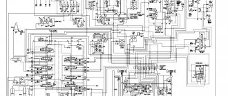
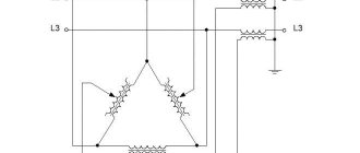
An example is typical failures of the common stabilizer ASN-10000/1-EM. The device consists of three identical parts - three 1-phase stabilizers designed to stabilize only their phase. The heart of the device is a step-up autotransformer. Together with the contactor and the input circuit breaker, it belongs to the power section.
The schematic diagram of ASN-10000/1-EM is shown in the figure below.
The principle of operation of electromechanical equalizers is based on smooth regulation of output parameters. The voltage changes due to the sliding of an electrical contact along the winding of the autotransformer by means of an electrical drive. A slider is attached to the axis of the electric motor, which, by moving, normalizes the output parameters.
The following characteristic malfunction that occurs during the operation of electromechanical stabilizers and methods for its elimination deserve special attention - lack of stabilization of the output voltage.
The first sign of such a problem is the smell of smoldering parts. It is not without reason that the reversible motor is called the “Achilles heel” of electromechanical devices. The voltage stabilizer controller constantly monitors the value of the output parameters. The rotor rotates constantly and this gradually wears out the engine itself.
One malfunction can lead to others, for example, the failure of an entire motor control cascade assembled on a pair of transistors. In addition to these elements, resistors located in their collector circuit melt due to overheating.
Of course, it is better to replace a worn-out electric motor, but sometimes a skillful attempt to power it is crowned with success. This is the easiest way to revive the engine:
- disconnecting the engine from the circuit;
- supplying 5 V to its pins from a powerful power source, for example, from an ATX computer power supply.
This results in annealing of small “garbage” on the motor brushes. The normal current consumption of the engine should not go beyond 90–160 mA. Since the motor is of a reversible type, the voltage must be applied at least twice with a change in polarity. After these impacts, the performance of the unit is temporarily restored.
Another solution to the problem is a slight replacement of the circuit with a narrowing of the adjustment range. The brush will simply move differently, bypassing the burnt-out sections of the transformer track.
Repair of relay stabilizers
Let's look at repairs as examples:
Resanta ASN-500/1-ts.
The most common errors are the messages "L" and "H", which represent the initial letters of the English words "low" and "high". That is, the indicators go beyond the acceptable parameters. On previous Resanta relay stabilizers with dial indicators, one could see a change in the output voltage in the range of 204–235 V when switching stages. On the current equipment, the recording shows 220 V, but in fact it is the same +- 6%, according to the passport data.
There is a problem with the relay switching slowly, which affects the protective shutdown of the air conditioning compressor. The fact is that the manufacturer uses cheap capacitors of very low quality. If you replace the electrolytes, the problem will be solved.
The main thing is not to forget about power. What is written on the body nameplate is true for an input voltage of 200 V; in reality, for a low voltage (170–180 V), the power should be 2 times less.
Resanta SPN-9000.
The operating principle of this relay stabilizer is based on stepwise regulation of the output voltage. Stabilization is provided by a microprocessor. Switching of the autotransformer taps is performed by five powerful relays, which are controlled by transistor switches. The stability of the output voltage depends on the switching resolution (5–20 V).
The main problem with SPN-9000 is burnt or stuck contacts in the relay. These problems quite often arise during the operation of the relay stabilizer. And also if the input voltage does not correspond to the range of threshold values, stabilization will not work. It happens that immediately when the device is turned on, the fuses are knocked out, and this is how the short-circuit protection is triggered.
Due to a relay malfunction, transistor switches “fly”. The relays must be replaced or restored. To do this, you need to remove the covers from the relay, then remove the moving contact, free it from the spring and carefully clean all relay contacts with sandpaper. Finally, clean all contacts with special gasoline and reassemble the relay in reverse order. Then solder all the transistors and check the integrity of the transitions. If necessary, replace the transistors with new ones.
If you need to connect, say, an electric oven (9 kW), to a stabilizer, then you cannot find a better device for this than the Resanta voltage stabilizer. And if minor defects arise, the service workshops will quickly and professionally eliminate them on the basis of warranty. Timely repairs are the key to the durability and reliability of the device even after the warranty period.
There are various breakdowns, and sometimes it is difficult to understand whether the operating conditions according to the instructions were simply not followed, or whether the device is faulty. However, problems can exist, and as a result, a problem may arise at the most inopportune moment. A repair company will always help you correctly establish the “diagnosis” and effectively eliminate them.
In the video: simple repair of the RESANTA stabilizer 15 kW 3 phase.
Simple repair of stabilizer RESANTA 15KW 3PHASE
Power surge and equipment burned out! What to do?
Common situation? We assure you that you are not alone who is looking for an answer to this question. And every year the number of victims of power surges increases. For example, not a month goes by on the popular YouTube without posting another video about the burnt-out equipment of Russian residents from various parts of Russia. And the reason for this is sudden surges and voltage drops in the electrical network.
We are sorry if you find yourself in a similar situation. To help you at least somehow, we recommend watching the first video - from it you will learn where to turn first.
Our company’s specialists remind you that the quality of Russian electrical networks, unfortunately, is not getting better from year to year. And the best way to protect your household appliances from breakdown is to prevent an emergency from occurring. Agree, it is much more pleasant not to cause the equipment to break down, saving money, nerves and more valuable property, than to “search for the truth”, running through authorities and courts after the accident.
He who is forewarned is forearmed! To prevent expensive equipment from burning out due to another power surge, reliable protection is necessary. Voltage stabilizers are such protective devices. Below we have selected several models of single-phase stabilizers that are most suitable for both a private home and an apartment.
A voltage stabilizer is a complex device of an electromechanical or electrical type, the repair of which requires deep knowledge in the field of radio engineering, special tools and measuring equipment.
Main types of voltage stabilizer malfunctions and their causes
The most common breakdowns that users encounter in practice:
- Extraneous sounds (clicks, crackling, hum) accompanying the operation of the voltage stabilizer. The most likely cause of the problem is that the input voltage is below or above the operating ranges. In most cases, the permissible adjustment range of the device lies between 100 and 250 volts. It should be noted that even in good condition, the voltage stabilizer can produce a low hum. And during operation of relay devices you can hear clicks. Thus, the relays regulate the output voltage by switching the taps from the windings. If the device crackles and clicks too loudly, most likely the brush is sparking (in servo-driven models) or there are problems with the contacts in the internal wiring of the device.
- The voltage stabilizer does not support the load. If the device turns off under load, the reason may be: a) too high consumer power; b) problems with the stabilizer itself (if you did not change the devices connected to it); c) interturn short circuit or overheating of the electrical transformer (this option is possible if the stabilizer does not turn off immediately, but after working for some time). A similar malfunction in servo-driven (or electromechanical) voltage stabilizers can be caused by clogging of conductive parts with graphite chips associated with brush wear. During operation, the brush loses its texture and covers the transformer with graphite. This may cause overheating or short circuiting.
- The output voltage is not 220 volts. This problem may not be related to the voltage regulator itself. One possible reason is that the voltage in the network is too low and the device does not pull its output to the required level. If the mains power is within acceptable limits, then the stabilizer will require diagnostics and subsequent repairs. In relay voltage stabilizers, a similar problem is most often associated with a malfunction of one or more electromagnetic relays or their control unit. As a rule, it is based on a transistor. In electromechanical models, the voltage may not rise above a certain level due to clogging of the brush module with graphite shavings.
- Ineffective voltage stabilization. In practice, the problem looks like this: instead of a smooth operation, the voltage is stabilized by sudden jumps, which negatively affects both the stabilizer itself and the equipment connected to it. The most likely reason is failure of the switching device in one or more adjustment phases. In servo-drive models, the cause of this problem may be contamination of the windings or a problem with the gear motor. A gearbox malfunction is often accompanied by extraneous sounds: crackling, clicking, buzzing - this is gears slipping. In addition, in electromechanical devices, if the engine control elements fail, stabilization may be absent altogether. This can be noticed by the stop of the runner with the brush, which moves to the extreme point and freezes in place.
- The voltage stabilizer does not turn on or its machine switches off at the end of the timer countdown. The reason may be an overestimated or underestimated network voltage and subsequent tripping of the protection. Often the root cause is failed resistors responsible for the switching thresholds at the lower and upper voltage levels. In this situation, the stabilization board, unable to cope with its functions, goes into defense.
- The voltage stabilizer shows no signs of life. If, when you turn on the device, the indicators on it do not light up, and no voltage appears at the output, a comprehensive and scrupulous diagnosis will definitely be required. There are many reasons for the complete failure of the stabilizer: damage to electrolytic capacitors, burnout of tracks, board failure, motor malfunction. The complexity and cost of repairs will depend on the nature of the identified breakdown.
Also in this section, two more circumstances should be identified, which very often serve as the causes of various malfunctions of voltage stabilizers. Firstly, manufacturing defects, and secondly, incorrect installation and operation of the device. There are more problems associated with manufacturing defects, but incorrect installation often causes more serious breakdowns. To avoid built-in defects, you should buy equipment from trusted manufacturers. For example, RUCELF, “Resant”, “Energy”, “Leader”, SVEN. As for the second circumstance, the rules for the operation and installation of any voltage stabilizer are specified in the documentation attached to it.
The degree of difficulty of repairing various types of stabilizers
All devices are equipped with protection systems that determine the levels of input and output operating parameters to ensure their compliance with the nominal value. To carry out repair work, you must have measuring instruments, including an oscilloscope, and a circuit diagram of the device. It is necessary to measure the input and output voltage, the temperature conditions of the working units, exclude a short circuit, then look at the error code. The most difficult thing to diagnose is a failure in stabilizers equipped with triac switches - they are controlled by complex electronics. Measurements using an oscilloscope make it possible to identify a breakdown of a structural module, after which it is necessary to troubleshoot each radio component.
In relay-type devices, the relay that performs the function of switching the transformer windings most often fails. Due to frequent switching, the coil may jam or burn out, so if it breaks, it is necessary to check the functionality of all relays.
The simplest is to repair the electromechanical stabilizer - to see its reaction to changes in network parameters, just remove the housing. High precision and simplicity of design have made this type one of the most popular.
Stabilizer transformer overheating
If the transformer heats up without visible loads, there is most likely an interturn short circuit. However, the reason may also be due to broken switches.
In relay devices, the cause of overheating may be a jammed relay; in triac devices, one of the switches may break and short-circuit the output windings. In servo-drive stabilizers, there is no winding switching, but the brushes can short-circuit due to contamination - graphite filings or soot getting into the space between them. Servo-driven models require periodic cleaning of contact surfaces.
Repair and modification of servo stabilizers
The wear rate of the servo drive device and its contamination depend on two factors: room humidity and dust in the environment in which it is operated. To protect it from dust getting inside, the technician installs a computer cooler opposite the most used sector of the autotransformer. In addition to cleaning dust, the cooler performs the function of cooling the autotransformer.
Long-term storage of the stabilizer in a humid environment can lead to oxidation of the contact pads, which can interfere with the performance of the contact slider - dust can begin to spark and ignite.
Why voltage stabilizer errors occur: features of device operation
The operating principle of stabilizer control systems is to adjust the output parameters within 5 seconds. When the specified task cannot be completed within a specified period, an error occurs. In addition, the processor analyzes the causes of an emergency situation with an indication that reflects all the data collected by the control board. When the input data is normalized or the causes of the malfunction are eliminated, restarting the stabilizer is possible immediately in manual or automatic mode (depending on the settings).
Stages of repair of a servo stabilizer
When starting repairs, remove the contact slider from the servo drive shaft. Then the contact surfaces are cleaned until the metal shines using sandpaper. Finish polishing is performed using an eraser. Abrasive particles and debris are removed using a brush.
After this, they move on to inspecting the graphite brush. It may fail due to excessive heating resulting from its poor contact with the autotransformer plates. When moving the slider, sparking and increased heating lead to burnout, which, in turn, further contaminates the contact pads and the space between them. This situation contributes to an increase in contamination, which leads to burnout of the brush and complete failure of the transformer - it stops producing voltage. In Resanta devices, if the output voltage is interrupted, protection is triggered.
Repair of Resanta stabilizers most often consists of cleaning the contact areas and replacing brushes.
Sometimes the servo drive breaks down, which can be caused by:
- engine burning;
- gearbox wear;
- no tension.
You can check this mechanism by removing the motor along with the gearbox and turning the shaft by hand. Residents of Odessa will be able to quickly and efficiently repair any type of stabilizer at the 24Master service.
Repair
Repair of the Resanta stabilizer can be divided according to the type of breakdown.
Servo
First, let's look at a situation where the Resant servo motor fails. There are two ways out of this problem :
- Buy a new motor, then install it in the device.
- Try to repair the damaged one.
If everything is clear with the first case, then the second requires detailed consideration. It is important to understand that if the repair work is successful, the restored engine will not be able to work for a long time, i.e. this is a temporary measure.
All our actions will boil down to the following:
- We disconnect the motor with the servo drive from the overall structure. Then we connect it to a power source with sufficient power.
- It is necessary to supply a current of 5 V to the motor outputs. The current must be at least 90 mA.
- Carrying out these manipulations will normalize the operation of the stabilizer. Next you need to connect the motor back to the circuit.
Features of Resanta brand devices
It is not recommended to connect Resanta brand stabilizers to precision electronics, medical equipment, computers and LCD TVs. The reason for this is simple: in the event of a power surge in the network, the device’s protection will simply turn it off, and the output voltage may disappear for a short period of time, which can affect the operation of the equipment.
The advantages of Resanta devices include:
- high accuracy;
- performance;
- almost silent operation.
They are great for providing stable voltage in small factories and country houses - they can be connected to heating appliances, power tools, pumps, and automatic lines.
Repair of electromechanical voltage stabilizers
The main problem with such stabilizers is overheating. It is absolutely necessary to carry out maintenance of the stabilizer once every 1-2 months, depending on operating conditions. And the repair of voltage stabilizers must begin with cleaning.
The problem of overheating manifests itself primarily due to the fact that the graphite brush, when moving along the surface of the transformer, inevitably wears out, and its particles, along with dust and other debris, remain on the contact track.
Now, when the brush continuously “crawls” over the surface, it begins to heat up more, spark, the debris burns and burns to the copper surface. In the future, this negative effect will increase like an avalanche, and if measures are not taken, it will reach irreversible limits, when cleaning will no longer help.
Of course, thermal sensors will save the situation - these are the first “bells”. If the stabilizer suddenly starts to turn off on its own, you should urgently call a specialist and clean the surface.
Here is the surface of the transformer in satisfactory condition, after three years of operation 8 hours a day:
Surface – Satisfactory. And this is after washing with alcohol.
And here is what indifference to the state of the stabilizer can lead to. This is the same stabilizer, a different phase:
Surface condition – Very bad
Even if you clean off this deposit, the cross-sectional area of the wire will irreversibly decrease by 20-30%, which will increase the heating of the wire and brush, and lead to the pessimistic processes described above:
The surface of the autotransformer is close. The wire insulation is burnt out, an interturn short circuit is possible. The epoxy also fell off due to overheating.
Only “zero” sandpaper will help here. You need to clean as you go with the brush, then rinse thoroughly with alcohol and wipe dry with a clean cloth.
Servomotor repair
Another breakdown is a malfunction of the servomotor when it stops moving the brush. The engine must be removed, cleaned, blown, and lubricated. Since a DC motor with brushes is used, you can try to idle it in both directions from a DC source with a voltage of about 5 V.
This way, without disassembling it, you can clean its brushes a little, because the engine rotates (or rather, turns) only at an angle of up to 180 degrees.
Electronic board repair
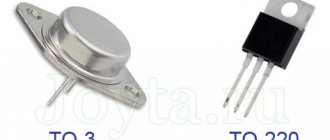
The engine may not turn over because there is no power coming to it. The power comes from the control board, from bipolar transistors. A pair of complementary transistors TIP41C and TIP42C is used, since the power supply to the circuit is bipolar. Transistors must be replaced in pairs, even if one is intact. And only one manufacturer.
The datasheet (documentation) for transistors can be downloaded at the end of the article.
Also in the same circuit, 10 Ohm resistors burn out (this is a consequence of the breakdown of transistors). When replacing resistors, nothing prevents you from increasing their power to 3 or 5 W, increasing operational reliability.
Well, replacing relays, transistors, limit switches and other small things - depending on the situation.
Power section repair
The power part includes autotransformers (I have already said enough about them). And also - a contactor and an input circuit breaker, whose contacts and terminals are lit. It must be periodically stretched, cleaned, and, if necessary, replaced.
To increase the life of transistors and servomotor
My reader and subscriber of the SamElectric.ru group Andrey Altukhov shared his circuit, which avoids overheating of transistors and increases the life of the motor due to the fact that the stabilizer does not respond to small (2-3 V) changes in the input voltage. The diagram and description are given “as is”; whoever repeats the modification - write in the comments!
Here's what Andrey writes:
The comments offered options on how to save the board and electric motor from premature failure. After the servo motor died twice in 2 years from overheating of the brushes and the control board in the area of the power transistors turned black, I decided to delve deeper into the issue. I played around with the gain factors of the op-amp, twisted it back and forth, but still the linear mode of operation did not go away.
I thought I could quickly solve the problem by installing a zener diode or a diode at worst, but the voltage levels are too low to make any difference. It is also possible to build something with a dead zone on transistors, but this is all a grandiose stucco on the board. Ideas swarmed in my head to insert a second op-amp and connect it to the break in the control circuit.
And then my father, looking over his shoulder, discovered in the diagram a completely unused (at least in the single-phase version) operational amplifier, already soldered on the board on legs 12, 13, 14 with output to pin 4XT2, which was simply hanging in the air. And then there were estimates of gain factors and feedback. As a result, this scheme was born. (picture based on one taken from the article).
Stabilizer circuit with response threshold
The threshold element is two back-to-back diodes connected in parallel. resistors R101 and R102 regulate the feedback and ultimately give the width of the dead zone. I settled on the 10k and 2.2k ratings which gives about 3V AC insensitivity. As soon as the voltage in the network changes to a larger value, one of the diodes opens and the electric motor is supplied not with a gradually increasing voltage, but immediately with a threshold, allowing the engine to immediately take a step. In addition, correction of the output voltage with a trimmer was required to set the output voltage. Well, with the second file I’m attaching what the printed circuit board looks like after modification.
Stabilizer printed circuit board after modification
Yes, in the original circuit, instead of a motor, I connected a small light bulb and a voltmeter. The tension gradually increases in either direction. In my circuit, the motor turns on when there is already a more serious voltage deviation. Moreover, if the voltage suddenly jumps in either direction, there will be no delays in operation.
Refinement affects accuracy, but in real life it does not matter much. The output voltage in my case has the right to vary +- 3 volts from the set nominal value. This is an inevitable price to pay for less nervousness of the servo. You can increase the gain of the first op-amp (blue text in the diagram) and get +- 1.5 volts.
There is one more moment. All experiments were carried out on a stabilizer in which the motor was replaced with a more expensive version with graphite brushes. It was not possible to check how it will spin with a standard motor.