Commissioning
The equipment can only be put into operation after preliminary preparation. First, a visual inspection of the unit is performed. There should be no defects on it. The design elements must correspond to the factory configuration.
A visual assessment of oil sealing materials and fasteners is carried out. If necessary, they should be tightened. Oil leaks are unacceptable
You also need to pay attention to the oil level in the tank. The indicator is at the level established by the manufacturer
If necessary, excess will need to be drained. If the coolant level is insufficient, you need to add liquid to the tank.
The insulators are wiped with a dry cloth and gasoline. You need to pour special oil into the thermometer sleeve body. Next you need to mount the measuring device.
If the indicator silica gel is wet, it must be replaced. It is located in the dehumidifier design. The equipment must be connected to ground. This also needs to be checked before starting.
The oil from the cooling system will need to be analyzed. It must meet the established requirements. After this, the plug is isolated. If the oil fluid does not meet the specified requirements, it must be completely drained. A new coolant of appropriate quality is poured into the system.
The resistance of the windings is measured. The switch must be set to the operating position. After this, the equipment can be connected to the network.
Determination by galvanometer method
There are several ways to determine whether the windings are connected correctly. The easiest way is to use a magnetoelectric system voltmeter. It is also called the direct current method.
To do this, a measuring device is connected to the ends of the winding being tested, and a constant voltage is applied to the other winding. The deflection of the arrow at the moment the key is closed will indicate the polarity of the winding connection. Such actions are performed for each winding.
You can also use a simple voltmeter when connecting AC voltage. To do this, a reduced alternating voltage is supplied to one of the windings, and the remaining two windings are connected in series and connected to a voltmeter. Absence or too small readings indicate that the windings are connected in opposite directions.
Maintenance and repair of TMG
Before pouring and topping up oil into the device, it is recommended to check that it has not been used previously. For each batch of oil that is poured and topped up into the device, it is necessary to have quality certificates from the supplier certifying the oil’s compliance with established standards and specifications. Information about the compliance of the oil supplied with the transformer is entered in the passport or transformer form
It is important to note that it is allowed to add oil to the device only with a breakdown voltage of up to 35 kV. Topping up is carried out as necessary
Interesting video: Production of TMG transformers
https://youtube.com/watch?v=fYUtgW0j2S0
Current repairs of transformers are carried out within the time limits established by the governing document “Rules for the technical operation of power plants and networks.” After completion of current equipment repairs, tests are carried out.
From the above description it is clear that TMG is unpretentious to use and requires minimal maintenance costs. In addition, the transformer device has a number of advantages, including an efficiency of up to 99%, excellent performance, as well as protection against overheating and short circuits.
Numbers
The listed designations may be followed by numerical values. This is the rated winding voltage in kV, power in kVA. For autotransformers, information about the voltage of the MV winding is added.
The marking may contain the first year of manufacture of the presented design. The power of the units can be 20.40, 63, 160, 630, 1600 kVA, etc. This indicator is selected in accordance with the operating conditions. Higher power equipment is available. This parameter can reach 200, 500 MVA.
The duration of use of Soviet-made transformers is about 50 years. Therefore, modern energy communications can use equipment manufactured before 1968. They are periodically improved and reconstructed during major overhauls.
Series control transformers
Table 5.23
| Snom, MBA | Regulating transformer type | Type of power autotransformer | Catalog data | Calculated data Qst, kvar | ||||||||
| Rated voltage of autotransformer, kV | Rated voltage of windings, kV | IR, % | Pk, kW | Рх, kW | Iх, % | |||||||
| VN | CH | NN | exciting | regulatory | ||||||||
| 240 | VRTDNU- 240000/35/35 | ATDTsTG-240000/220 ATDTsTG-240000/330 (ATDIT) | 230 230 | 121 121 | 11 38,5 | 11 38,5 | ±24,2 +24,9 —26,2 | 10,9-0-10,5 11,1-0-11,3 | 154 178 | 40 47 | 3,8 3,8 | 9120 9120 |
| 330 | 165 | 11 | 11 | ±33,8 | 11,8-0-11,8 | 183 | 40 | 3,8 | 9120 | |||
| 330 | 242 | 11 | 11 | +31,4 —33,1 | 10-0-10,1 | 85 | 30 | 4,0 | 9600 | |||
| 347 | 242 | AND | 11 | +38,3 —40,4 | 12,8-0-13 | 132 | 29 | 3,8 | 9120 | |||
| 347 | 242 | 38,5 | 38,5 | +24,9 —26,2 | 11,1-0-11,3 | 178 | 47 | 3,8 | 9120 | |||
| 92 | ODCGNP- 92000/150 | AODTSGN- 333000/750/330 | 750/ | 330/ | 15,75 | — | — | 6,67 | 185 | 110 | 0,7 | 644 |
Decoding transformers, examples
Current transformers are designated as follows: • T - The letter indicates that this is a current transformer • The second letter means the design: “P” - feed-through, “O” - support transformer, “Sh” - busbar, “F” - with a porcelain cover • The third designation indicates the insulation and cooling system of the transformer windings “L” - cast insulation, “M” - oil, Then it goes through the “-“ insulation class, climatic modification of transformers, and category of installations.
An example of decoding a current transformer TPL - 10UHL4 100/5A.
- T – current
- P – pass-through
- L – cast insulation
- Class 10 kV
- UH – temperate and cold climate
- 4 – fourth category
- 100/5A – transformation ratio is one hundred to five.
Examples of interpretation of voltage transformers: TM - 100/35 - three-phase oil transformer with natural circulation of air and oil, rated power 0.1 MVA, voltage class 35 kV; TDNS - 10000/35 - three-phase transformer with oil blowing, adjustable under load for the power plant’s own needs, rated power 10 MVA, voltage class 35 kV; VRTDNU - 180000/35/35 - boost transformer, regulating, three-phase, oil-cooled, type D, adjustable under load, with reinforced input, throughput power 180 MVA, rated voltage of the excitation winding 35 kV, rated voltage of the regulating winding 35 kV; LTMN - 160000/10 - linear transformer, three-phase, with natural circulation of oil and air, adjustable under load, throughput power 160 MVA, rated line voltage 10 kV. NKF-110-58U1 - cascade voltage transformer in a porcelain cover, rated voltage of the HV winding 110 kV, developed in 1958, climatic version - U1; NDE-500-72U1 - voltage transformer with a capacitive divider, rated voltage of the HV winding 500 kV, developed in 1972, climatic version - U1; TNP - 12 - zero-sequence current transformer, with alternating current bias, covering 12 cable cores; TNPSh - 2 - 15 - zero-sequence current transformer, with alternating current bias, busbar, covering 2 cable cores, rated voltage of the HV winding 15 kV.
EXAMPLES OF DECODING THE NAMES OF POWER TRANSFORMERS
TM - 100/35 - three-phase oil transformer with natural circulation of air and oil, rated power 0.1 MVA, voltage class 35 kV;
TDNS - 10000/35 - three-phase transformer with oil blowing, adjustable under load for the power plant’s own needs, rated power 10 MVA, voltage class 35 kV;
TRDNF - 25000/110 - three-phase transformer, with split winding, oil with forced air circulation, adjustable under load, with an expander, rated power 25 MVA, voltage class 110 kV;
ATDTsTN - 63000/220/110 - three-phase oil autotransformer with blowing and forced oil circulation, three-winding, adjustable under load, rated power 63 MVA, HV class - 220 kV, MV class - 110 kV;
AODTSTN - 333000/750/330 - single-phase oil autotransformer with blowing and forced oil circulation, three-winding, adjustable under load, rated power 333 MVA, HV class - 750 kV, MV class - 500 kV.
Marking
To select a unit that meets the network requirements, you will need to delve into the specifics of the labeling. Each oil-type installation is designated according to the following scheme:
TM-x/6(10) y(HL)1
The decryption looks like this:
- T – three-phase transformer.
- M – oil cooling system with natural circulation of liquid in the system.
- x – unit power (nominal), kW.
- 6(10) – voltage of the HV winding, kV.
- у(ХЛ)1 – climatic type of design.
Based on the information provided, everyone can choose the right type of device. It will best meet consumer requirements.
Features transformer marking
In the markings that are presented on the equipment, the data can be divided into several subgroups. In order to avoid confusion in the data, you should first familiarize yourself with the sequence of their indication. To write the markings of any device, you should take into account some groups:
- Group 1 A allows you to indicate the type to which the device belongs. That is, the equipment is of the power type or is an autotransformer.
- 2 group T indicates the type of network for which the device in question is used. The most common are single-phase and three-phase.
- Group 3 DC is a cooling system with mandatory circulation of oil and air.
- Group 4 T demonstrates the number of windings that were used in the production of equipment.
- Group 5 H is intended to demonstrate voltage data, the adjustment of which is carried out under load.
- Group 6 includes an indication of all the numbers and data that characterize the equipment - power, winding voltage, installation features and much more.
If you familiarize yourself with the information about each of the above categories in more detail, it will be much easier to select the appropriate equipment for specific purposes.
Decoding alphabetic characters
The main brands of transformers are presented in the form of letter designations and look like this: TM, TMZ, TSZ, TSZS, TRDNS, TMN, TDNS, TDN, TRDN, TRDCN.
- T – three-phase device design;
- P – division of the low voltage winding into two parts;
- C – dry type of transformer;
- M – the presence of oil cooling of the transformer, air and oil circulation occurs naturally;
- C - in transformers of this type, the circulation of water and oil is forced. The movement of water occurs through the pipes, and the oil flows between them in the form of a non-directional flow.
- MC - means natural circulation of air in the transformer and forced circulation of oil with non-directional flow;
- D – corresponds to an oil transformer with forced oil circulation and natural air circulation;
- DC – refers to the design of a transformer with forced circulation of air and oil in the cooling system;
- N – the device voltage is adjusted under load;
- C - if this letter is placed at the end of the marking, this indicates the use of a transformer in the power plant itself.
- Z – means a sealed transformer model, in which there is a nitrogen cushion and no expander.
DECODING OF THE NAMES OF POWER TRANSFORMERS
The following letter designations are accepted for power transformers:
Table 1 - Decoding of alphabetic and digital designations of the name of the power transformer
Note: forced air circulation is called blowing, that is, “with forced air circulation” and “with blowing” are equivalent expressions.
Transformer marking
Any transformer has different design features, scope of application, rated voltage and climatic conditions, etc. You need to be able to correctly decipher the markings with alphanumeric designations of the characteristics of transformers: its power, cooling system, number of windings, voltage on the high-voltage and low-voltage windings.
Any number or letter on the plate printed on the transformer body has its own meaning. Some letters may be missing, others cannot be present at the same time, for example “O” and “T” single-phase and three-phase.
The most common letter designations for transformers: TM, TS, TSZ, TD, TDTs, TMN, TDN, TC, TDG, TDTG, OTs, ODG, ODTG, ATDTsTNG, AOTDTSN, etc.
- A – denotes an autotransformer
- The first letter marks the phasing: T - three-phase, O - single-phase;
- The letter P (with split winding) after the number of phases in the designation indicates that the low voltage winding is represented by two (three) windings.
- The second letter indicates the cooling system: M - natural oil, i.e. natural circulation of oil, C - dry transformer with natural air cooling of an open design, D - oil with blowing, i.e. with blowing of the tank using a fan, C - forced circulation of oil through a water cooler, DC - forced circulation of oil with blast.
- The presence of the second letter T means that the transformer is three-winding; two-winding does not have a special designation.
- N - voltage regulation under load (OLTC), absence - presence of switching without excitation (SWB),
- G - lightning-resistant.
- The letter designations are followed by (Un) rated power of the transformer (kVA)
- separated by a fraction - the class of the rated voltage of the HV winding (kV). In autotransformers, the voltage class of the MV winding is added in the form of a fraction. Sometimes the year of production of transformers of this design began is indicated.
The scale of rated power of three-phase power transformers and autotransformers (current state standards 1967 - 1974) of high-voltage networks is built so that there are power values that are multiples of ten: 20, 25, 40, 63, 100, 160, 250, 400, 630, 1000 , 1600 kVA, etc. Some exceptions are capacities of 32000, 80000, 125000, 200000, 500000 kVA
The service life of transformers is quite long and is equal to 50 years. Nowadays, you can find industrial transformers manufactured back in 1968 that have undergone a major overhaul.
Power scale of transformers produced in the USSR: 5, 10, 20, 30, 50, 100, 180, 320, 560, 750, 1000, 1800, 3200, 5600, ..., 31500, 40500, kVA, etc.
In order not to get confused in the table of indicated data, you can divide it into six groups. An example of determining indicators for the AODTSTN transformer - 333000/750/330 single-phase oil autotransformer with blowing and forced oil circulation, three-winding, adjustable under load, rated power 333 MVA, HV class - 750 kV, MV class - 500 kV
Marking of terminals and branches of power transformers
1 Designation order
Marking of terminals and branches of power transformers should be done using a notation system based on alternating capital letters of the Latin alphabet and Arabic numerals. The use of letters 1 and 0 is not allowed. Examples of markings - to hell. 5-12.
Note
. Lowercase letters are acceptable, but uppercase letters are preferred.
EXAMPLES OF MARKING OF OUTPUT AND BRANCHES OF POWER TRANSFORMERS
Marking of phase windings
a) phase winding with branches in the middle; b) phase winding with coarse and fine control stages at one end of the winding; c) phase winding, consisting of two parts connected in series or parallel; d) phase winding, consisting of two parts connected in series, each of which is in the middle of the branch
Crap. 5
Marking of single-phase transformers
a) a transformer with two windings without branches; b) a transformer with three windings without branches; c) autotransformer without branches
Crap. 6
Marking of single-phase autotransformers
a) a winding with branches placed between the series and common windings; b) a tap winding placed at the end of the series winding; c) a tapped winding, one end of which is connected to the connection between the series and common windings
Crap. 7
Marking of three-phase two-winding transformers
a) Un/Un-0; b) Un/Un-6; c) Un/D-5; d) Un/D-11
Crap. 8
Marking of three-phase three-winding transformer (Un/Un/D-0-5)
Crap. 9
Low voltage winding markings. 9 if it is connected in an open triangle
Crap. 10
Marking of a three-phase autotransformer (Unavto/D-0)
Crap. eleven
Marking of a linear control transformer with an exciting winding connected in a triangle
Crap. 12
Letters and numbers may be omitted. Adjacent groups of numbers that have different semantic meanings should be separated by a dot. For example, instead of the designation 1 U 11, the abbreviation 1.11 is allowed.
Care should be taken to ensure that there is no confusion between two such designations.
2 Ends of phase windings
The two ends of the phase windings connected to the linear or neutral terminals should be marked with numbers 1 and 2, respectively.
If the phase windings at the ends have branches intended for connection to off-load tap-changers or on-load tap-changers that lead to the linear or neutral terminals, then these terminals should be marked with numbers 1 or 2, respectively.
With such a system for marking pins and branches on winding diagram drawings, the same winding direction is assumed for all windings. The polarity of ends 1 and 2 of all windings of one rod is also always the same.
Note.
Marking of autotransformers with two phase windings having a common end - according to clause 4.
3 Line and neutral terminals
The linear terminals of the winding of a three-phase power transformer should be designated by the letters U, V, W, which are placed before the numbers given in clause 2. If necessary, these letters can also be placed before the numbers given in clauses 5 and 6.
The neutral of a winding connected in a star or zigzag should be designated by the letter N.
Winding designation
The different windings of the transformer should be designated by numbers, which are placed before the letters given in paragraph 3. The highest voltage winding should be designated by number 1, and the other windings by numbers 2, 3, 4 ... in descending order of rated voltages.
For autotransformers in which two windings have a common end, this end should be marked with the number 2 (an example is shown in Fig. 6, c).
Note.
If several windings have the same rated voltage, the use of the corresponding numerical designation should be agreed upon between the manufacturer and the consumer.
5 Series-parallel connection
If the phase windings consist of several parts that can be connected in series or parallel, the ends of these parts should be marked with numbers 1, 2, 3, 4... while the linear or neutral ends of the phase windings are marked with numbers 1 and 2 in accordance with the requirements of paragraph 2 .
6 Branch markings
Branches supplied to on-load tap-changer or tap-changer devices should be designated by a group of numbers arranged in ascending order. The values of these numbers must be greater than those used to designate the linear and neutral terminals and to designate the ends of parts of the phase windings connected in series or parallel.
Numbering should start from the branch closest to the end, marked with the number 1. The marking of tap-changeable windings shall be based on that connection which produces the highest effective number of turns for the winding connected to the tap-changer or on-load tap-changer.
Windings of autotransformers with taps located between the series and common windings or at the end of the series winding, as well as windings, one end of which is connected to the connection between the series and common windings (Fig. 7c), should be numbered as a series winding.
In more complex cases, for example, when two transformers are placed in one tank, agreement between the manufacturer and the consumer is required.
(Introduced additionally, Amendment No. 3)
INFORMATION DATA
1 DEVELOPED AND INTRODUCED by the Ministry of Electrical Industry. DEVELOPERS - I.YU. Meleshko (topic leader); V.Yu. Frenkel, Ph.D. tech. sciences; V.M. Kirillov; S.I. Mayzus
2 APPROVED AND ENTERED INTO EFFECT by Resolution of the USSR State Committee on Standards dated September 24, 1985 No. 3005
3 The standard fully complies with ST SEV 1102-86
The standard complies with international standards IEC 76-1-76, IEC 76-2-76, IEC 76-4-76, IEC 76-5-76
The international standard IEC 616-78 has been introduced into the standard.
4 INSTEAD GOST 11677-75
5 REFERENCED REGULATIVE AND TECHNICAL DOCUMENTS
| Designation of the referenced technical document | Item number | Designation of the referenced technical document | Item number |
| GOST 9.014-78 | 8.2.5 | GOST 14192-96 | 8.1.6 |
| GOST 12.1.004-91 | 4.1; 7.2 | GOST 14209-85 | 3.2.1.8 |
| GOST 12.2.007.0-75 | 3.8.1; 4.1 | GOST 15150-69 | 1.2; 1.3; 3.9.10; 8.3.2; Annex 1 |
| GOST 12.2.007.2-75 | 3.5.41; 4.1; 4.2 | ||
| GOST 12.2.024-87 | 4.4; 7.2 | GOST 15543.1-89 | 1.2; 1.3 |
| GOST 721-77 | 2.3; 9.4.2.1; 9.4.2.4 | GOST 16110-82 | Introductory part |
| GOST 1516.1-76 | 3.2.2.1; 3.2.2.2; 6.2.3 6.3; 6.5; 6.9; 9.4.1 | GOST 17221-91 | 3.6.1.5 |
| GOST 17412-72 | 1.3 | ||
| GOST 3484.1-88 | GOST 17516.1-90 | 1.3 | |
| GOST 3484.5-88 | 3.9.8; 7.2 | GOST 18620-86 | 7.2 |
| GOST 7174-75 | 3.5.47 | GOST 20243-74 | 3.3.1.1; 7.2 |
| GOST 7746-89 | 3.5.11 | GOST 20690-75 | 3.2.2.1; 6.2.3; 6.3; 9.4.1 |
| GOST 8865-93 | 2.5; 3.2.1.5; 3.2.1.6; 3.9.1 | GOST 21023-75 | 7.2 |
| GOST 9680-77 | 2.3 | GOST 21128-83 | 2.3 |
| GOST 9920-89 | 3.5.6 | GOST 21130-75 | 8.1.5 |
| GOST 10198-91 | 8.2.2 | GOST 22756-77 | 7.2 |
| GOST 10434-82 | 3.5.2 | GOST 23216-78 | 8.2.3; 8.2.8; 8.3.2; 8.4.1 |
| GOST 10693-81 | 3.5.1 | GOST 23865-79 | 3.5.1 |
| GOST 13109-97 | 2.4 | GOST 24126-80 | 3.5.10 |
6 The validity period was lifted according to Protocol No. 5-94 of the Interstate Council for Standardization, Metrology and Certification (IUS 11-12-94)
7 REISSUE (January 1999) with Amendments No. 1, 2, 3, 4, approved in May 1987, September 1987, September 1989, December 1990 (IUS 8-87, 12-87, 12-89, 3-91)
General structure and principle of operation
Each transformer is equipped with two or more windings inductively coupled to each other. They can be wire or tape, covered with an insulating layer. The windings are wound on a core, also known as a magnetic circuit, made of soft ferromagnetic materials. If there is one winding, such a device is called an autotransformer.
The operating principle of the transformer is quite simple and understandable. An alternating voltage is applied to the primary winding of the device, which leads to the flow of alternating current in it. This alternating current, in turn, causes the creation of an alternating magnetic flux in the magnetic circuit. Under its influence, an alternating electromotive force (EMF) is induced in the primary and secondary windings. When the secondary winding closes to the load, alternating current also begins to flow through it. This current in the secondary system differs in its own parameters. It has individual current and voltage indicators, number of phases, frequency and voltage waveform.
Energy systems that transmit and distribute electricity use power transformers. With the help of these devices, the values of alternating current and voltage are changed. However, the frequency, number of phases, current or voltage curve remain unchanged.
The design of the simplest power transformer includes a magnetic core made of ferromagnetic materials, mainly electrical steel sheets. The primary and secondary windings are located on the magnetic core rods. The primary winding is connected to the AC source, and the secondary winding is connected to the consumer.
In power transformers, when flowing through the turns of the winding, an alternating magnetic flux is also created, which arises in the magnetic core. Under its influence, an EMF is induced in both windings. The output voltage may be higher or lower than the original voltage, depending on whether a step-up or step-down transformer is used. The EMF value in each winding varies according to the number of turns. Thus, if you create a certain ratio of turns in the windings, you can create a transformer with the required ratio of input and output voltages.
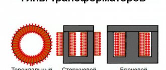
Basic types and principle of operation of transformers
There are different types of transformers, shown accordingly in electrical diagrams. For example, if there is only one winding, such devices belong to the category of autotransformers. The main designs of these devices, depending on the core, are rod, armored and toroidal. They have almost the same technical characteristics and differ only in the manufacturing method. Each device, regardless of type, consists of three main functional parts - magnetic circuit, windings and cooling system.
The schematic representation of a transformer is closely related to the principle of its operation. All design features are reflected in the electrical circuit. The primary and secondary windings are very clearly visible. Current is supplied to the primary winding from an external source, and the ready-made rectified voltage is removed from the secondary winding. Current conversion occurs due to an alternating magnetic field arising in the magnetic circuit.
What does the TMG-25 transformer consist of?
The device includes several main parts:
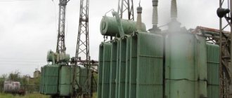
- Tank and radiators
- Special lid covering the tank
- Expansion tank and active part
The tank has a plug, which is necessary for taking coolant samples, and a plate that grounds the device.
The top of the tank body is covered with weather-resistant grayish paint. The shade can be different: from gray to dark graphite. In addition, at your request, we can replace the color of the coating with any other one. The tank includes the following main parts:
- Thick steel walls
- Upper frame
- Radiators
- Hinges that help lift the device
- Dense bottom on which support legs are installed
The main task of the expansion tank is to compensate for various changes in the volume of coolant, which may depend on the external environment. This part is equipped with:
- Markings for the minimum and maximum amount of liquid.
- Wide neck into which coolant can be added.
TCM transcript
These electromagnetic devices are designed for three-phase circuits and are made without additional cooling, that is, dry. Their power ranges from 0.16 to 1 kVA, most often used for rectifiers and semiconductor power supplies. One of the advantages of such a device is that it can be located in the housing in any position, horizontal or vertical.
The decoding of its markings is as follows:
After which its power and additional conditions of climatic use are indicated.
In industry and in everyday life, many dry and oil-based transformers for various purposes are used. If there is a factory plate on them, then deciphering it is not difficult. The main thing is to apply it in accordance with the type of electrical installation, power, and also that the voltages and currents of all windings are used under normal conditions without overloads. Then these unpretentious, reliable and low-maintenance devices can last for decades.
Examples of current transformer connections
In Figure 1, b, three current transformers and relays P1, P2 and P3 are connected in a star. Relay P4 is connected to the neutral wire.
In normal mode, as well as during a three-phase short circuit, currents flow in relays P1, P2, P3, but there is no current in relay P4, since the geometric sum of the currents passing through relays P1, P2 and P3 is zero.
In case of two-phase short circuits, the current flows in two damaged phases (for example, in phases A and C), relays P1 and P3 are activated. The sum of the currents of two phases passes through relay P4. But in this case they are equal, but opposite in direction. Therefore, relay P4 does not work.
In the event of a single-phase short circuit (for example, a phase B ground fault), the damaged phase relays P2 and P4 are activated. Thus, the star neutral wire is a zero-sequence current filter. Direct and negative sequence currents do not pass through it, since each of these systems adds up to zero.
The principle of operation of differential protection of transformer T is explained in Figure 1, c. On the left are the directions of currents under normal load, as well as during an external short circuit (I1 and I2 - currents in the power circuit). It is easy to see that the current in relay P is close to zero, since the secondary currents of the current transformers (see arrows) pass through the relay towards. Of course, the current transformer ratios must be properly selected.
When there is a short circuit inside the transformer (Figure 1, on the right) or at its terminals, the direction of the current changes, the currents in the relay are summed up and it is triggered. Figure 1, d shows an example of differential protection of a transformer with a star-delta connection, that is, with a shift of primary and secondary currents by 30°.
In such cases, it is necessary, in addition to compensating for the inequality of primary and secondary currents (by selecting the transformation ratios of current transformers), to compensate for the phase shift. Phase shift compensation is achieved by delta-connecting current transformers installed on the star side of the power transformer, and star-connecting current transformers installed on the delta side.
Instructions for use
If you plan to work with the device, then you need to study the rules for its use. You also need to remember that the device is considered quite dangerous. If you use a TMG transformer, then study the recommendations for use:
- Operate the device only in comfortable clothing.
- Do not work with a device that has dents or cracks.
- Try to regularly check the KTP for the amount of oil in the tank.
- Before using the device, check its functionality.
- To store the transformer, you may need a dry place.
Main characteristics of the transformer
Figure 1.3 shows the appearance of the transformer TRDN-40000/110.
Figure 1.3 – Appearance of transformer TRDN-40000/110
In accordance with the accepted notation system, the abbreviation of the transformer TRDN-40000/110-U1 is deciphered as follows: T - three-phase transformer; P - the presence of a split low voltage winding; D - cooling is carried out with natural circulation of oil and forced air circulation; N - voltage regulation is carried out under load on-load tap-changer; 40000 – rated power of the transformer, kV•A; 110 – voltage class of the high-voltage winding, kV; U1 – climatic version, placement category according to GOST 15150. The main parameters of this transformer are given in Table 1.1 [].
Table 1.1 – Technical parameters of TRDN-40000/110-U1
| Rated frequency, Hz | 50 |
| Winding connection diagram and group | Υн/Δ-Δ-11-11 |
| Rated value of HV voltage, kV | 115 |
| Rated value of LV voltage, kV | 11 |
| Short-circuit voltage (HV-LV), % | 10,5 |
| No-load current, no more, % | 0,55 |
| On-load tap-changer control stages in the HV neutral | ±9x1.78% |
| Full service life, years | 25 |
The requirements for power transformers state that to ensure long-term and reliable operation of transformers it is necessary to ensure:
- compliance with the required load, temperature conditions and voltage levels;
- compliance with the characteristics of transformer oil and insulation within the established standards;
- maintaining transformer cooling devices, oil protection, voltage regulation, etc. in good condition.
EXAMPLES OF DECODING THE NAMES OF REGULATION TRANSFORMERS
VRTDNU - 180000/35/35 - boost transformer, regulating, three-phase, oil-cooled, type D, adjustable under load, with reinforced input, throughput power 180 MVA, rated voltage of the excitation winding 35 kV, rated voltage of the regulating winding 35 kV;
LTMN - 160000/10 - linear transformer, three-phase, with natural circulation of oil and air, adjustable under load, throughput power 160 MVA, rated line voltage 10 kV.
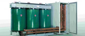
Three-phase power transformers, two-winding, sealed distribution TMG series
Power from 16 to 2500 kVA, voltage class up to 20 kV general purpose with natural oil cooling with non-excited tap changers, connected to an alternating current network with a frequency of 50 Hz. Designed to convert alternating current and serve for the transmission and distribution of electrical energy in power plants.
TMG transformers are designed to operate in the following conditions:
- installation height above sea level no more than 1000 m;
- ambient air temperature from minus 45 °C to plus 40 °C – for transformers of the “U” version; from minus 60 °C to plus 40 °C – for transformers of the “UHL” design.
- Transformer placement category – 1.
Oil sealed transformers TMG allow operation in conditions of placement categories 2, 3, 4.
Transformers of the TMG series are not intended for operation in conditions of shaking, vibration, shock, in explosive and chemically active environments.
Voltage regulation is carried out with a completely switched off transformer using a non-excited switch (OPS), which allows voltage regulation in steps of 2.5% in a range of up to ±5%.
TMG transformers are hermetically sealed and do not have expanders. Corrugated transformer tanks are safe and highly reliable. Temperature changes in oil volume are compensated by changes in the volume of the tank corrugations due to their elastic deformation.
TMG transformers are equipped with float-type oil indicators and spring-type safety valves configured to operate at an excess pressure of 40 kPa.
At the customer's request, in transformers with a power of 100 kVA and above, located indoors, it is possible to install an electrical contact pressure-vacuum gauge.
To measure the temperature of the upper layers of oil, TMG transformers are equipped with liquid thermometers of the type TTZh-M 240/66 150S TU25-2022.0006.90.
Transformers with a power from 1000 to 2500 kVA, intended for operation indoors or under a canopy, are equipped with a pressure gauge signaling thermometer of the TKP type upon customer request.
There is a ground plate and drain plug at the bottom of the tank. The design of the plug allows, when partially unscrewing it, to take an oil sample.
The TMG transformer is equipped with a plate with basic technical data attached in a visible place.
Transformers with a power of 400 kVA and above are supplied with transport rollers that allow longitudinal or transverse movement of the transformer. By special order of the consumer, the plant can equip transformers with a capacity of 63 kVA or more with transport rollers.
Three-phase three-winding transformers and autotransformers 220 kV
Table 5.18
| Type | Snom, MBA | Regulation limits | Catalog data | Calculation data | Qx, kvar | |||||||||||||||||||
| Unom of windings, kV | IR, % | Pk, kW | Рх, kW | Iх, % | RT, Ohm | Xt, Ohm | RT, Ohm | Xt, Ohm | ||||||||||||||||
| VN | CH | NN | VN-SN | VN-NN | CH-NN | VN-SN | VN-NN | CH-NN | VN | CH | NN | VN | CH | NN | ||||||||||
| TDTN-25000/220 | 25 | ±12×1 % | 230 | 38,5 | 6,6; 11 | 12,5 | 20 | 6,5 | 135 | — | — | 50 | 1,2 | 5,7 | 5,7 | 5,7 | 275 | 0 | 148 | 300 | ||||
| TDTNZh-25000/220 | 25 | ±8×1,5% | 230 | 27,5; 38,5 | 6,6;11;27,5 | 12,5 | 20 | 6,5 | 135 | — | — | 50 | 1,2 | 5,7 | 5,7 | 5,7 | 275 | 0 | 148 | 300 | ||||
| TDTN-40000/220 | 40 | ±12×1 % | 230 | 38,5 | 6,6; 11 | 12,5 | 22 | 9,5 | 220 | — | — | 55 | 1,1 | 3,6 | 3,6 | 3,6 | 165 | 0 | 125 | 440 | ||||
| TDTNZh-40000/220 | 40 | ±8×1,5% | 230 | 27,5; 38,5 | 6,6;11; 27,5 | 12,5 | 22 | 9,5 | 240 | — | — | 66 | 1,1 | 3,9 | 3,9 | 3,9 | 165 | 0 | 125 | 440 | ||||
| ATDTsTN-63000/220/110 | 63 | ±6×2% | 230 | 121 | 6,6;11; 27,5; 38,5 | 11 | 35,7 | 21,9 | 215 | 45 | 0,5 | 1,4 | 1,4 | 2,8 | 104 | 0 | 195,6 | 315 | ||||||
| ATDCTN- 63000/220/110/0,4* | 63 | ±8×1.5% PBB at 0.4 kV- ±2×2,5% | 230 | 121 | 0,4 | 11 | 180 | 33 | 0,4 | 1,2 | 1,2 | 120 | 104 | 0 | ||||||||||
| ATDTsTN-125000/220/110 (denominator: release after 1985) | 125 | ±6×2% | 230 | 121 | 6,3;6,6 10,5; 11;38,5 | 11/ 11 | 31/ 45 | 19/ 28 | 290/ 305 | 85/ 65 | 0,5 | 0,5/ 0,52 | 0,5/ 0,52 | 1,0/ 3,2 | 48,6/ 49,0 | 0 | 82,5/ 131 | 625 | ||||||
| ATDCTN- 125000/220/110/0,4* | 125 | ±6×2% PBB at 0.4 kV- ±2×2,5 % | 230 | 121 | 0,4 | 11 | 14 | 14 | 305 | 54 | 0,25 | 0,52 | 0,52 | 52 | 49 | 0 | ||||||||
| ATDCTN- 200000/220/110 | 200 | ±6×2% | 230 | 121 | 6,3;6,610,5; 11; 15,75; 38,5 | 11 | And | 20 | 430 | 125 | 0,5 | 0,3 | 0,3 | 0,6 | 30,4 | 0 | 54,2 | 1000 | ||||||
| ATDCTN- 250000/220/110 | 250 | ±6×2% | 230 | 121 | 10,5; 38,5 | 11,5 | 33,4 | 20,8 | 520 | — | 145 | 0,5 | 0,2 | 0,2 | 0,4 | 25,5 | 0 | 45,1 | 1250 | |||||
* Designed for connecting electrical networks with voltages of 220 and 110 kV and powering substation auxiliaries with a power of 0.63 and 1.25 MV-A with a voltage of 0.4 kV, respectively.
Notes.
1. For AT, the power of the LV winding is 50% of the rated one.
2. Voltage regulation is carried out by an on-load tap-changer in the HV neutral (±8×1.5%; ±12×1%) or on the MV side (±6×2%).
Design and principle of operation of transformers
Humanity has come up with several dozen ways to produce electricity: generating electricity from heat, using water energy, wind, sun and many others. The trouble is that consumers of this energy can be several hundred kilometers away from the place of its production.
From an economic and technical point of view, it is most profitable to deliver electricity through wires over such distances under high voltage - in this case, resistance losses in the circuit are minimal. However, both producers and consumers use current with much lower potential differences. It is to change the voltage of an electric current over a wide range of values that devices such as transformers are used.
The simplest transformer consists of two coils with a winding that are not electrically connected to each other. A metal core passes through them, which is common to both windings. A current source is connected to one of the coils - this is the primary winding, and a consumer is connected to the other, which is called the secondary.
The principle of operation is based on one of the main properties of an alternating electric field: it can create a magnetic field, which, in turn, can create electricity. The current running through the primary winding creates an alternating magnetic field in the core. Since the core (its other name is a magnetic circuit) is common to two windings, the magnetic field extends to both coils.
If electricity produces a magnetic field on the primary winding, then on the secondary the reverse process occurs: the magnetic field “forces” the electrons inside the coil to run in a certain direction, thereby inducing an electric current in it. Its value directly depends on the applied voltage and the number of turns on the winding.
There are two modes of operation of transformers: step-down and step-up. In the first case, the voltage decreases, in the second, it increases.
Almost any transformer can operate in both modes: it is enough to switch the incoming current and consumer between the coils.
Industrial transformers reach enormous sizes and generate large amounts of heat. To remove it, air or liquid cooling is used. The liquid can be oil, water or other liquids with dielectric properties. Coolant circulation in such installations can be carried out either naturally (due to the difference in the densities of hot and cold coolant) or forced.
Existing types of transformer markings
Regardless of any features of the equipment, marking of transformers is mandatory depending on the type of equipment. In the case when the marking begins with the letter A, this means that we are talking about an autotransformer. If this letter is missing, then you have a device in front of you that is of the power type.
The number of phases is required. Thanks to this, it is possible to give preference to equipment that operates from a household or industrial network. In the event that equipment is connected to a three-phase network, you will definitely see the letter T in the marking of transformers. If we are talking about single-phase models, they are designated by the letter O. Transformer markings are mainly used in household networks.
Depending on the installation category, it is possible that some special designations may be used in practice. For voltage or current transformers, they can be completely different. Also, the difference lies in the fact that the equipment is of a protective type and for measuring current. The first ones are used to measure alternating current values. Voltage transformers are not used to transmit electric current, which has high power. The main role in the marking of transformers is played by their design features. Structures that belong to the transitional type, for example, have the letter P in their abbreviation. If it is not there, you will see support-type equipment.
Design
The characteristics of the presented equipment indicate the presence of a list of necessary structural elements. Passport data reveals information about the composition of the system. It includes a welded tank with a lid and an active part. The body has an oval configuration. There are LV and HV terminals on the cover. TM transformers include a switch, an expander with an oil level indicator, and an air drying device.
The active part includes a magnetic drive with winding contours. The core has upper and lower beams. Oil transformers have a switch installed. It controls the tap windings. The contours have a cylindrical configuration. The core is made of special ferromagnetic steel, and the circuits are made of copper.
The operating instructions provide for the convenience of installing equipment, the weight of which in some cases exceeds 4 thousand kg, two hooks on top of the tank. There is a grounding plate and a plug at the bottom that allows you to drain the oily substance from the system. The description of this design suggests the possibility of taking samples of the cooler. Dimensional units are firmly installed on the prepared surface. For this purpose, plates with holes for mounting on the foundation are installed in the lower part. This procedure is specified in the passport data.
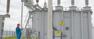
Features of operation
Installations of the presented category are operated strictly in accordance with generally recognized standards. Commissioning and monitoring of equipment condition is carried out by trained, experienced employees.
The presented equipment is installed in areas with moderate and cold climates. It is prohibited to store fire hazardous, explosive, chemical substances, gases, or liquids nearby.
The unit is installed at an altitude of no more than 1 km above sea level. The design is not designed to withstand vibration, mechanical shock or shaking. The work cycle is quite long. The equipment is turned off for scheduled repairs and maintenance. If signs of malfunction appear, in an emergency situation, the power is immediately turned off.
The ambient temperature can reach from +40 to -45ºС for category U1. Climatic modification HL1 allows operation in the range from +40 to -60ºС. Relative humidity is 80%. The above conditions contribute to long-term, efficient operation of the equipment.
Having considered the features, operating principles and designations of STMI transformers, you can choose the right device that meets the needs of consumers.
Differences between TM and TMG
Rice. 5. Comparison of TMG and TM transformers
TMG transformers are often compared with TMs that are similar in marking; let’s look at the comparative characteristics with one of these units using the following table as an example:
Table: comparative characteristics of TMG and TM transformers
| TMG | TM |
| Features a more efficient tank design, allowing for improved cooling in a less complex design | A classic thick-walled tank with outdated type radiators is used. |
| Due to the sealing of the transformer, the oil does not come into contact with atmospheric air, which allows it to maintain dielectric properties. | The liquid dielectric is affected not only by internal processes, but also by moisture from the surrounding air. |
| The design without an expander is widely used. | An expansion tank is installed on the lid to ensure the container is filled. |
| Float type oil level indicator | Tubular oil level indicator |
| Problems with overpressure due to the lack of an expansion tank; gases are released through the valve. | When heated, excess gas or oil easily moves into the expander or through the breathing cartridge into the surrounding space. |
| It is necessary to constantly monitor the pressure on the pressure gauge. | The pressure is independently stabilized by the expander. |
| Low reliability indicators from mechanical or vibration impacts on the transformer. | High degree of reliability, the transformer is not afraid of mechanical influences. |
| It is not suitable for major repairs with opening the cover, since re-sealing with oil injection is difficult. | Major repairs can be performed any number of times. |
| Service life from 20 to 30 years | Service life from 40 to 50 years |
Voltage transformers
Sample of filling out an application for the plant's products
Requirements for placing orders for transformers intended for export
Overhead safety device NPU-6(10)
| Schemes for protecting voltage transformers from ferroresonance |
| Grounded voltage transformers ZNOL.02-27 III ! NEW! Voltage class, kV: 27 Rated voltage of the secondary winding, V: 100 Rated power, VA, in accuracy class: from 20 to 40 |
| Grounded voltage transformers ZNOL.03 ! NEW! Voltage class, kV: 6 or 10 Number of secondary windings: 2 Voltage of secondary windings, V: 100/√3; 100/3 |
| Grounded voltage transformers 3NOL.06 Voltage class, kV: 3-35 kV Number of additional windings: 2 or 3 Voltage of secondary windings, V: 100/3; 100; 110/3; 110; 100/√3 Load in accuracy class 0.5, VA: 30-75 |
| Grounded voltage transformers ZNOLP with built-in safety device Voltage class, kV: 3, 6 or 10 Number of additional windings: 2 or 3 Voltage of secondary windings, V: 100/3; 100; 110/3; 110; 100/√3 |
| Grounded voltage transformer ZNOLPM with built-in safety device Voltage class, kV: 6 or 10 Number of secondary windings: 2 Voltage of secondary windings, V: 100/3 or 100 or 100/√3 |
| Grounded voltage transformers ZNOL.01PMI with built-in safety devices Voltage class, kV: 10 Number of secondary windings: 2 Voltage of secondary windings, V: 100/√3; 100/3 |
| Three-phase anti-resonance group of voltage transformers 3xZNOL.04P Voltage class, kV: 6 or 10 Voltage of the main secondary winding, V: 100 Rated power, VA, in accuracy class: from 60 to 225 |
| Three-phase group of voltage transformers 3xZNOL.06 and 3xZNOLP Voltage class, kV: 6 or 10 Voltage of the main secondary winding, V: 100 Voltage of the additional secondary winding, V: from 90 to 110 Rated power, VA, in accuracy class: from 90 to 900 |
| Three-phase group of voltage transformers 3xZNOLPM Voltage class, kV: 6 or 10 Voltage of the main secondary winding, V: 100 Voltage of the additional secondary winding, V: from 90 to 110 Rated power, VA, in accuracy class: from 30 to 270 |
| Grounded voltage transformers ZNOL for outdoor installation Voltage class, kV: 3, 6 or 10 Voltage of the main secondary winding, V: 100/√3; 110/√3 Voltage of the additional secondary winding, V: 100/3; 100; 110/3; 110; 100/√3 Rated power, VA, in accuracy class: from 15 to 300 |
| Grounded voltage transformers ZNOL.01P(I)-20 Voltage class, kV: 20 Number of secondary windings: 3 Voltage of secondary windings, V: 100/√3; 100/3 |
| Grounded voltage transformers ZNOL.06-27(35) (ZNOLE-35) Voltage class, kV: 27 or 35 Voltage of the main secondary winding, V: 100/√3; 100 Voltage of additional secondary winding, V: 100/3; 127 Rated power, VA, in accuracy class: from 10 to 120 |
| Grounded voltage transformer ZNOL-35 III Voltage class, kV: 27 or 35 Voltage of the main secondary winding, V: 100/√3; 100 Voltage of additional secondary winding, V: 100/3; 127 Rated power, VA, in accuracy class: from 10 to 120 |
| Grounded voltage transformer ZNOL.01PMI-35 Voltage class, kV: 35 Voltage of the main secondary winding, V: 100/√3 Voltage of the second main secondary winding, V: 100/√3 (for a four-winding transformer) Voltage of the additional secondary winding, V: 100/3 Rated power, VA: from 10 to 600 |
| Ungrounded voltage transformers NOL Voltage class, kV: 3, 6 or 10 Voltage of the main secondary winding, V: 100; 110 Rated power, VA, in accuracy class: from 15 to 300 |
| Ungrounded voltage transformers NOL.08 Voltage class, kV: 3, 6 or 10 Voltage of the main secondary winding, V: 100; 110 Rated power, VA, in accuracy class: from 15 to 300 |
| Ungrounded voltage transformers NOL.08-6(10)M Voltage class, kV: 6 or 10 Voltage of the main secondary winding, V: 100 Rated power, VA, in accuracy class: from 20 to 200 |
| Ungrounded voltage transformers NOL.08.3-6(10)M Voltage class, kV: 6 or 10 Voltage of the main secondary winding, V: 100 Rated power, VA, in accuracy class: 20 |
| Three-phase group of voltage transformers NOL.08-6(10)M ! NEW! Voltage class, kV: 6 or 10 Voltage of the main secondary winding, V: 100 Rated power, VA, in accuracy class: from 60 to 600 |
| Ungrounded voltage transformers NOLP with built-in safety device Voltage class, kV: 6 or 10 Voltage of the main secondary winding, V: 100; 110 Rated power, VA, in accuracy class: from 30 to 300 |
| Ungrounded voltage transformers NOLP-6(10)M ! NEW! Voltage class, kV: 6 or 10 Voltage of the main secondary winding, V: 100 Rated power, VA, in accuracy class: from 20 to 200 |
| Ungrounded voltage transformers NOL-10M IV ! NEW! Voltage class, kV: 6 or 10 Voltage of the main secondary winding, V: 100 Rated power, VA, in accuracy class: from 20 to 200 |
| Ungrounded voltage transformers NOL.11-6.O5 Voltage class, kV: 6 Voltage of the main secondary winding, V: 100; 127; 220 Voltage of additional secondary winding, V: 100/3; 100; 110/3; 110; 100/√3 Rated power, VA, in accuracy class: from 30 to 250 |
| Ungrounded voltage transformers NOL.12 Voltage class, kV: 0.66, 6 or 10 Voltage of the main secondary winding, V: 100; 127 Rated power, VA, in accuracy class: 30 Designed for use on river and sea vessels |
| Ungrounded voltage transformer NOL-20, NOL-35 Voltage class, kV: 20 or 35 Voltage of the main secondary winding, V: 100 Rated power, VA, in accuracy class: from 10 to 600 |
| Ungrounded voltage transformers NOL-20(35) III for outdoor installation Voltage class, kV: 35 Voltage of the main secondary winding, V: 100 Rated power, VA, in accuracy class: from 50 to 600 |
| Voltage transformers NTMIA-6(10) Voltage class, kV: 6 or 10 Voltage of the main secondary winding, V: 100 Voltage of the additional secondary winding, V: from 97 to 103 Rated power, VA, in accuracy class: from 75 to 600 |
| Ferroresonance protection device SZTn |
Back
Top
Voltage transformer terminal designation system
Instrument transformers, depending on the circumstances, can be connected into a star, partial star, delta, open delta and open delta. Relays, meters and measuring instruments powered by measuring transformers can also be connected in different ways, both among themselves and with measuring transformers. In the diagrams, if required, the beginnings of the windings are indicated by asterisks (see, for example, Figure 1, d). Below are typical examples.
Figure 1. Terminal marking system and examples of current transformer connections. Asterisks indicate the beginning of the windings.