To measure quantities with large values, current transformers are used. For this purpose, the primary winding of the device is connected in series to a circuit with alternating current, the value of which must be measured. The secondary winding is connected to measuring instruments. There is a certain proportion between the currents in the primary and secondary windings. All transformers of this type are highly accurate. Their design includes two or more secondary windings, to which protective devices, measuring instruments and metering devices are connected.
What is a current transformer?
Current transformers are devices in which the secondary current used for measurements is in proportion to the primary current coming from the electrical network.
The primary winding is connected to the circuit in series with the current conductor. The secondary winding is connected to any load in the form of measuring instruments and various relays. A proportional relationship arises between the currents of both windings, corresponding to the number of turns. In high voltage transformer devices, insulation between the windings is carried out based on the full operating voltage. As a rule, one end of the secondary winding is grounded, so the winding and ground potentials will be approximately the same.
All current transformers are designed to perform two main functions: measurement and protection. Some devices may combine both functions.
- Instrument transformers transmit the received information to connected measuring instruments. They are installed in high voltage circuits in which it is impossible to directly connect measuring instruments. Therefore, ammeters, meters, current windings of wattmeters and other metering devices are connected only to the secondary winding of the transformer. As a result, the transformer converts alternating current, even a very high value, into alternating current with indicators that are most acceptable for the use of conventional measuring instruments. At the same time, the isolation of measuring instruments from high-voltage circuits is ensured, and the electrical safety of operating personnel is increased.
- Protective transformer devices primarily transmit the received measurement information to control and protection devices. With the help of protective transformers, alternating current of any value is converted into alternating current with the most suitable value, providing power to relay protection devices. At the same time, relays that are accessible to personnel are isolated from high voltage circuits.
Description and purpose of devices
High-power electrical installations operate with power reaching several hundred W, at a current strength exceeding tens of kA. It is logical that it is simply impossible to measure quantities of this order with conventional instruments. For this purpose, current transformers are used, which simultaneously perform several functions. Thanks to the advent of converters, the potential of measuring instruments has significantly expanded. And the possibility of transmitting energy through galvanic isolation opened up.
The design of the devices is their additional advantage. For example, if there were standard devices for measuring the voltage of high-voltage alternating current networks, they would be very large and expensive. In contrast to transformers, which look relatively compact and are protected from adverse external factors and mechanical damage.
The main task of current transformers is to convert the primary value (supplied voltage) to a level that allows connecting measuring instruments and protection systems. An additional function is to provide galvanic isolation between low and high power consumers, eliminating risks for operating personnel.
Simply put, the purpose of the instruments is to simulate certain conditions and processes in electrical installations for safe readings.
Purpose of transformers
Current transformers belong to the category of special auxiliary devices used in conjunction with various measuring devices and relays in alternating current circuits. The main function of such transformers is to convert any current value to values that are most convenient for measurements, providing power to disconnecting devices and relay windings. Due to the insulation of the devices, service personnel are reliably protected from high voltage electric shock.
Measuring current transformers are designed for electrical circuits with high voltage, when there is no possibility of direct connection of measuring instruments. Their main purpose is to transmit received data on electric current to measuring devices connected to the secondary winding.
An important function of transformers is to control the state of the electric current in the circuit to which they are connected. During connection to the power relay, constant checks of the networks are performed, the presence and condition of grounding. When the current reaches an emergency value, protection is activated, turning off all equipment in use.
Connection diagrams
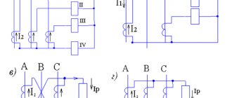
The windings of three-phase CTs can be connected in delta or star (see Fig. 8). The first option is used in cases where it is necessary to obtain a higher current strength in the circuit of the second winding or it is necessary to phase shift the current in the secondary coil relative to the primary one. The second connection method is used if it is necessary to monitor the current strength in each phase.
Figure 8. Connection diagram of a three-winding CT with star and delta
If there is an isolated neutral, a circuit can be used to measure the current difference between the two phases (see A in Fig. 9) or a partial star connection (B).
Figure 9. Connection diagram of a CT for a difference of two phases (A) and a partial star (B)
When it is necessary to power the ground fault protection, a circuit is used that allows the currents of all phases to be summed (see A in Fig. 10). If a current relay is connected to the output of such a circuit, it will not respond to a short circuit between phases, but will definitely work if a ground fault occurs.
Fig. 10. Connections: A – for the sum of currents of all phases, B and C – serial and parallel connection of two-winding CTs
In conclusion, we give two more examples of connecting the secondary windings of a CT to take readings from one phase:
The secondary coils are connected in series (B in Fig. 10), making it possible to measure the total power.
The secondary windings are connected in parallel, which makes it possible to reduce the CT, since the current in these coils is summed, while in the line this indicator remains unchanged.
Principle of operation
The operating principle of current transformers is based on the law of electromagnetic induction. Voltage from the external network is supplied to the power primary winding with a certain number of turns and overcomes its total resistance. This leads to the appearance of a magnetic flux around the coil, captured by the magnetic circuit. This magnetic flux is located perpendicular to the direction of the current. Due to this, losses of electric current during the conversion process will be minimal.
When the turns of the secondary winding, located perpendicularly, intersect, the electromotive force is activated by the magnetic flux. Under the influence of the EMF, a current appears that is forced to overcome the total resistance of the coil and the output load. At the same time, a voltage drop is observed at the output of the secondary winding.
Possible malfunctions and signs of malfunctions
Transformers face various negative factors during operation. These include high continuous loads. Mechanical damage. Environmental adverse influences. Short circuits. Overloads, device overheating and much more. For transformers to operate, it is also necessary to create certain conditions in the rooms where they are located. Regularly analyze work processes, carry out diagnostics and promptly eliminate violations, preventing breakdowns. Not allowed:
- High temperature and humidity in the room.
- Lack of optimal oil level.
- Work with internal damage.
The following will help identify deviations in the early stages:
- Load checks.
- Maintaining a maintenance log.
- Change the sound of workflows.
- Temperature.
- High vibrations.
- Winding inspection.
Classification of current transformers
All current transformers can be classified depending on their features and technical characteristics:
- By appointment. Devices can be measuring, protective or intermediate. The latter option is used when connecting measuring instruments to current circuits of relay protection and other similar circuits. In addition, there are laboratory current transformers that are characterized by high accuracy and a variety of transformation ratios.
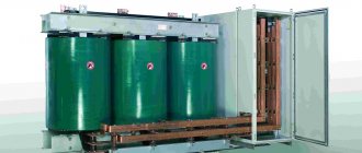
- By installation type. There are transformer devices for external and internal installation, overhead and portable. Some types of devices can be built into cars, electrical devices and other equipment.
- According to the design of the primary winding. Devices are divided into single-turn or rod, multi-turn or coil, and also bus, for example, TSh-0.66.
- Internal and external installation of transformers involves pass-through and support methods for installing these devices.
- Transformer insulation can be dry, using bakelite, porcelain, and other materials. In addition, conventional and capacitor paper-oil insulation is used. Some designs use compound filling.
- Depending on the number of transformation stages, devices can be one- or two-stage, that is, cascade.
- The rated operating voltage of transformers can be up to 1000 V or more than 1000 V.
Areas of application
Current transformers, for one purpose or another, are always actively used in all areas - industrial, commercial, household and others, where the operation of the electrical network, in particular high voltage, is envisaged. In cases where it is necessary to convert current, according to the principle of magnetic induction, from a primary alternating current circuit to another - a secondary one. At the same time, the differences between one and the other can be very diverse - voltage, number of phases, frequency, etc.
In addition, protective devices that allow devices and devices to be connected via galvanic isolation prevent risks for both the consumer and the operating personnel or user. Current transformers are indispensable for measuring indicators, especially regular or continuous ones.
Parameters and characteristics
Each current transformer has individual parameters and technical characteristics that determine the scope of application of these devices.
Rated current
Allows the device to operate for a long time without overheating. Such transformers have a significant heating reserve, and normal operation is possible with overloads of up to 20%.
Rated voltage
Its value should ensure normal operation of the transformer. It is this indicator that affects the quality of insulation between the windings, one of which is at high voltage and the other is grounded.
Transformation ratio
It is the ratio between the currents in the primary and secondary windings and is determined by a special formula. Its actual value will differ from the nominal value due to certain losses during the transformation process.
Current error
Occurs in a transformer under the influence of magnetizing current. The absolute value of the primary and secondary current differs by exactly this amount. The magnetizing current leads to the creation of a magnetic flux in the core. As it increases, the current error of the transformer also increases.
Rated load
Determines the normal operation of the device in its accuracy class. It is measured in Ohms and in some cases can be replaced by such a concept as rated power. The current value is strictly standardized, so the power value of the transformer completely depends only on the load.
Nominal limiting factor
It represents the multiple of the primary current to its rated value. The error of this multiplicity can reach up to 10%. During calculations, the load itself and its power factors must be rated.
Maximum secondary current ratio
Presented as the ratio of the maximum secondary current and its rated value when the effective secondary load is rated. The maximum multiplicity is related to the degree of saturation of the magnetic circuit, at which the primary current continues to increase, but the value of the secondary current does not change.
Explanation of markings and symbols
All specialized, and even household devices, are marked without fail. And if for the seller, the barcode or QR code plays an important role, then for the consumer, the main thing is the alphanumeric index, reflecting the characteristics and basic information about the purchase. The marking of current transformers contains the following basic indicators:
- The first capital letter “T” indicates the name of the product – current transformer.
- The second indicates the type of construction - “P” pass-through, “O” support, “F” porcelain cover.
- The third indicates the type of insulation - “M” oil and “L” cast.
- The number after the combination of letters is the insulation class. Indicated simply by a number, it implies a value in kV.
- The letters “U” and “X” mean the possibility of operation in moderate and cold climates. In most models "UH".
- It is followed by a number indicating the category of the device.
- At the end of the index, the transformation ratio is indicated through “/” - the primary and secondary windings.
Calculation methods
The calculation algorithm for selecting devices is quite simple and is based on the characteristics of the current transformers themselves. Each indicator plays a role. The optimal voltage value, transformation ratio, error level, device design, etc. are determined. All calculations are made using formulas. The transformation ratio, for example, must be determined according to the minimum and maximum values of the primary current. Taking into account data on the connected device and the installed power of power transformers. The most popular is the simplified calculation method. Taken:
- Primary winding voltage.
- Secondary.
- Secondary winding current.
- And its power.
Provided that there are several windings, the total value is taken as the calculated one. The result is displayed using the formula.
All data, designations and formulas are indicated in the regulatory documentation. In addition, the main recommendation: pay attention to technical aspects, not cost. This always helps with any choice.
Accuracy class and error
To ensure the correct recording of electricity consumption readings, regulatory standards establish the following accuracy classes for current transformers:
- commercial metering meters: 0.2;
- technical accounting counters: 0.5.
The conditions are considered met if the actual load on the secondary winding of the transformer does not exceed the rated load for a given accuracy class.
In addition, the device parameters must provide current and angular errors. For normal operation of protection devices and accurate readings, the current error should not exceed 10%, and the angular error should not exceed 7°.
The result of constructing a vector diagram of currents in the illustration:
Iµ=I1+I2, other parameters and notations are taken from the school physics course. By carrying out test measurements, you can verify whether the assembled circuit complies (or does not comply) with the requirements of GOST and PUE.


