The electrical supply diagram of a private home is a lot of organized cables, wires, and protective devices. The correct selection of parameters and characteristics of the circuit elements guarantees the safety and comfort of property owners.
If the circuit is drawn up correctly, taking into account the requirements of the PUE and other regulatory documents, there is nothing to fear - there will always be light and warmth in the rooms, and electrical appliances will not break due to power surges or short circuits in the network. Therefore, special attention should be paid to electrical design.
We suggest you understand all the intricacies of this process. The article outlines the general requirements for designing an electrical network, provides practical advice on choosing wires, and also discusses in detail typical electrical wiring diagrams.
In addition, we have prepared a review of common mistakes, taking into account which will help to avoid shortcomings in the development and installation of power supply networks.
Cable laying methods
The electrical network at the dacha consists of an internal and external part. There are 2 methods of laying external cable: overhead and underground.
Air
Wiring at the dacha by air is carried out using 2 methods. In the first case, the SIP cable (self-supporting insulated wire) directly connects the power line and the facade of the house . In the second case, a metal cable is laid from the centralized electrical network to the facade , and any wire is fixed to it. In both cases, it is necessary to use insulating fasteners for installing current-carrying conductors.
Please note the following during installation :
- The maximum distance from a power line pole to a house is 25 m. If the distance is greater, additional supports must be installed.
- It is necessary to carefully calculate the load-bearing capacity of the cable and take into account that in winter the load due to ice will be higher.
- Ultraviolet radiation gradually destroys the insulating sheath of the wire. It is recommended to use additional protection - corrugation.
- The distance of the wire to the ground must be at least 6 m.
Wiring by air is easier to perform. Installation speed is minimal. However, the cable is subject to intense wind loads.
Underground
The cable can be laid underground. This method is more labor-intensive, but in this case the cable is reliably protected from external influences.
- The depth of the trench is 70 cm. If the cable is laid in a protective pipe and the distance from the power line to the shield is no more than 5 m, you can dig a trench 50 cm deep.
- The distance between the trench and the foundation is at least 60 cm. If the wire is brought into the house through the foundation, an additional piece of pipe will be required. The hole is made in the foundation; laying the cable under it is prohibited.
- The distance between green spaces and the trench is 75 cm, to the sewerage or water supply system - 100 cm, to the gas pipeline and tall trees - 200 cm.
- Only armored cables with good insulation protection are laid in the ground.
Despite the greater amount of work, this installation option is cheaper.
What should be installed immediately after entering?
The cable introduced into the house is connected to a circuit breaker designed for the electrical power allocated for the facility (the rated protection current of the input circuit breaker for a single-phase network is up to 40 A). It will operate in an emergency such as over-powering, short circuit or fire. A meter is installed after the machine, and then, according to the diagram, the network is wired.
Experts advise that you first draw the internal wiring diagram of the electrical network in detail on a computer or on paper.
4
Preparing the circuit
To conduct electricity in the country, they draw up a diagram. There are 2 options:
- standard - the diagram is drawn on paper, the drawing should be approximate, so everyone can do it;
- modern - they use special programs.
The work is quite simple. They depict an approximate plan of the house and indicate on the diagram the installation points of sockets, switches, lamps, junction boxes, and equipment that also consumes electricity. It is advisable to indicate the location and number of cables here.
The wiring diagram makes it easier to calculate loads.
- The load from all consumers is summed up: lamps, fan, electric kettle.
- They are divided into groups : 1 connection for a washing machine, 2 for a group of lamps in the room. 3 – for the second group, 4 – for the module with sockets. This reduces the number of wires and avoids current overloads.
- Calculate consumer power - total and for each line. Based on these data, the parameters of electrical engineering are determined.
For calculations, product passports or reference data will be required.
Procedure
Work on electrifying a garden plot begins with submitting an application to a specialized organization.
This is done even if joining the centralized network is not planned in the near future.
Contacting relevant organizations
If you need to install electricity in your dacha, you must submit an application to the nearest distribution zone. When visiting an organization, a written application for permission is drawn up.
It states:
- information about the owner of the dacha;
- location of the site;
- planned capacity.
Within 2 weeks, the power engineers draw up technical specifications with an attached contract. The applicant must sign it no later than 30 days after receipt.
List of required documents for filing an application
Before contacting a network company, prepare the following documents:
- certificate of ownership of the land (if there is a house, they also collect papers for it);
- power of attorney (when a contract is executed by another person);
- electrification plan for the site and existing buildings.
Project development
After signing the contract, a power supply diagram is drawn up. This requires specific skills. If there are none, contact the designers. The executor can be a network organization or a private bureau. The right choice of designer is the key to obtaining a high-quality plan and the absence of problems at the approval stage at the energy company. Installation work is carried out taking into account the diagram. You cannot deviate from it. An individual project is not required when connecting a house to a centralized network with a power of up to 20 kW.
Connection deadlines
Electricity installation is carried out within 4 months after submitting the application. This period applies in the absence of plans for the construction or reconstruction of energy supply facilities. In some cases, the application review period increases to 6 months.
The work will require poles, cables and auxiliary equipment. They are installed at the expense of the network company.
If the distance to the power line exceeds 500 m, the application is processed individually.
Cable selection
For external wiring there is not too much choice. When laying by air, it is best to take SIP . For underground installation, choose an armored cable with copper or aluminum conductors in an insulating winding. Preference is given to copper: such wiring can withstand heavy loads. But if there are no high-power consumers at the dacha and no high-power consumers are expected, you can get by with a cheaper option with aluminum conductors.
Inside the building, the choice is determined by the installation method. Wires can only be installed in a hidden way - in grooves, in pipes. Cables may be laid openly.
For high loads, cables and wires with copper conductors are used.
Section Definition
For electricians in a country house, the cable cross-section is calculated based on the load . The total and load of each circuit is taken into account. First, calculate the expected load. Then divide it by the network voltage. In this way, the permissible current is calculated. Select a cable with a supply cross-section according to the PUE tables - for aluminum and copper conductors.
The cable cross-section is selected with a reserve. For an outlet, it is recommended to choose an option with a cross-section of at least 2.5 square meters. mm, and for lighting - 1.5 sq. mm.
Effect of moisture on wiring
The second feature of a country house is that it is used temporarily. In most cases, country houses are used during the summer. In cold weather, dachas, so to speak, are left to their own devices. That is, at this time the owners practically do not visit them. How does this fact affect the wiring?
It is worth mentioning here that in cold weather dampness increases in country houses. In essence, dampness is increased humidity. And moisture is the main enemy of electricity. As a result, moisture accumulates on the wires, their connections and in the internal contacts of the sockets. In some cases, condensation settles. This manifests itself when the owner arrives at his country house and begins to heat it.
Moisture and condensation lead to oxidation and destruction of contacts. The situation gets worse when a powerful current begins to pass through these contacts. As a result, they become very hot. The end result of this is premature failure of the electrical wiring and the need to install a new one.
The only option to prevent this problem is to maintain the same temperature in the country house. But there is no point in heating a house if no one lives in it. As a result, experts recommend laying the wiring in an open way. This will allow for quick replacement of damaged wires and there will be no need to destroy the plaster in order to install new wiring.
Another feature of a country house is that the plot on which it is located is isolated. This means that in order to ground the electrical wiring near a country house, you need to install a grounding loop. Lightning protection is also mandatory.
Tools and materials for work
To install electrical wiring you will need the following:
- scissors, pliers, screwdrivers;
- screwdriver; grinder with diamond blade, wall chasers;
- hammer, mounting chisel;
- spatula and materials for sealing walls - alabaster, gypsum;
- fasteners;
- wires and cables of the required section;
- sockets, switches, socket boxes;
- circuit breakers, RCDs, distribution boxes;
- connecting terminals.
To work with electrical wiring, it is better to take a tool with rubber handles.
An example of an electrical network configuration for a two-story house
- Input machine
- Counter
- Input (fire) RCD
- Circuit breaker 2nd floor
- RCD of sockets on the 2nd floor
- 1st floor circuit breaker
- RCD of 1st floor sockets
- Automatic sockets on the 1st floor
- Automatic well pump, utility unit, gazebo, outdoor lighting
- RCD of external lighting
- Sockets (double or triple): 18 pcs. (11 pieces on the 1st floor, 7 pieces on the 2nd floor)
- Switches: single-key – 11 pcs. (6 pcs. on the 1st floor, 5 pcs. on the 2nd floor), two-key – 2 pcs. (on the 1st floor)
- Switch-socket: 1 pc. (on the 1st floor)
- Ammo: 10 pcs. (6 pieces on the 1st floor, 4 pieces on the 2nd floor)
An example of filling out a distribution panel for a cottage (diagram TN-CS)
13
Cable entry into the house
The cable is introduced into the building through the wall or through the foundation.
In the first case, in the wall and a fragment of a pipe - metal or plastic - is installed. A cable is passed through it.
In the second, a hole is drilled in the foundation. Here, only a steel pipe is installed, insulated on both sides with non-flammable material and fixed with concrete. Then pass the cable through the pipe. Inside the building, a hole is drilled in the floor. Install a tube of smaller diameter and pull out the conductor.
Concrete floors are difficult to drill. In this case, it is better to introduce the wire through the wall.
Which switches and sockets are best to use?
For any powerful devices, sockets with the maximum permissible starting current are installed. For low-power devices you can use standard ones.
They can be:
- (Internal) To install a socket or switch, it is necessary to prepare a recess in the wall into which the box is mounted. The electrical contents of a switch or socket are secured in this box;
- (External) In this case, the housing of the outlet or switch protrudes from the wall. It is more convenient to mount them - a substrate is installed on the wall surface, on which a switch or socket is mounted.
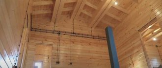
Laying wiring in a wooden house
Most often today, internal switches and sockets are used. Basically, they are selected taking into account the interior decoration of the room, or they simply install white appliances.
Installation of internal wiring
Electrical wiring in a country house is installed exactly according to the calculated diagram. You can’t replace something at the last moment and not take into account the difference in load. Installation is carried out in a certain order.
Marking
Use chalk and pencil. The location is chosen taking into account the standards of SNiP, PUE and your own convenience. It is recommended to immediately mark the location of the wire . After this, it is easier to calculate how much cable is actually required. The wiring is pulled along the walls. It is allowed to lay conductors on the floor if it is filled with cement screed and in this case the wire must be hidden in a corrugation to prevent mechanical damage.
Wall chipping
If installation is carried out openly or in a protective corrugation, it is enough to simply mark the position of the wiring on the wall.
If you want to hide the cable, you need to make grooves in the walls of the required depth and width - grooves. This can be done using a hammer drill with a chisel attachment, an angle grinder or a wall chaser, whatever you have on hand.
For sub-grids and junction boxes, holes in the wall are drilled with crowns - diamond or carbide-tipped. The standard sizes for the socket box are diameter 68 mm and depth 45 mm. But if non-standard types of modules are used, the dimensions of the holes will be different.
If modules with several sockets and switches are installed, several holes are drilled in a row, and the partitions between them are knocked out with a hammer drill or chisel.
Laying lines
At the dacha, wiring is most often installed in an open way. It is not necessary to use corrugation if you take a fairly well-insulated cable - VVG or VVGng, for example. To achieve a more aesthetic appearance, it is recommended to hide the wiring under the baseboard - floor or ceiling.
When laying hidden, the wiring is placed in grooves and fixed in them with putty, alabaster or special staples. The groove is filled completely with material.
Installation of junction boxes and sub-grids
Distribution boxes and socket boxes are mounted after laying the wires. Instructions are followed.
- Holes are drilled in the socket box for the power cable and auxiliary wires.
- The landing hole is coated with alabaster. Check: when you press on the bottom, the nest should not fall through.
- Coat it with alabaster on the outside of the socket box and insert it into the hole. The socket box should hold tightly. Alabaster dries in 2 hours, after which work can continue.
The distribution box can also be placed on alabaster. If the walls of the house are wooden, the shield is secured with screws and dowels.
Line connection
The connection of the socket and switch is carried out after finishing work, if any was carried out.
- In the junction box they find the zero, phase and supply wire of the circuit. The veins come in different colors, so it's easy.
- From a group of cables, find the one that is led from the installation site of the socket, switch, equipment and strip the ends. The cable cores are screwed into phase, neutral and power. Close the shield.
- Then the end of the cable that goes to the socket is cut into cores and the ends are stripped. The phase is connected to the first terminal of the socket, and the neutral to the second. The ground connection is connected to the connector in the middle of the socket.
- Insert the socket into the socket box, fix it with self-tapping screws and screws through the tabs. Then the decorative part is attached.
All connection and installation work is carried out when the power supply is disconnected.
What should electrical wiring cover in a summer cottage?
When planning electrical wiring, it is important to consider the following connection points:
- Lighting from outside and inside.
- Sockets and switches.
- Number of household appliances, their location.
- Load in laundry room, workshop.
- Garages, bathhouses, sheds, toilets and showers on the site.
It is advisable to foresee all currently expected and possible load on the network in advance in order to install the system immediately, without redoing or adding to it. If there is a need for special machines, then a three-phase circuit is needed. If the consumption is expected to be no more than 4 kW per hour, then single-phase will suffice.
Security
Electricity in a dacha requires compliance with the same safety measures as in a multi-storey building. To prevent emergency situations and electric shock, it is necessary to use RCDs, circuit breakers and grounding.
Grounding
The structure is buried in the ground at a distance of no closer than 1 m and no further than 10 m. A grounding wire coming from the junction box is connected to the electrode closest to the house.
Protective automation
To protect the electrical network from overloads, and equipment from short circuits and insulation burnout, protective devices are used.
Circuit breakers are mounted on each consumer group separately. When the set voltage or current is exceeded, the module turns off the serviced circuit. After normal current supply is restored, it turns on.
RCD is a protective module that responds to leakage currents that occur when insulation is damaged or when the neutral wire is broken. The RCD cuts off the current supply to the consumer and thereby prevents a fire in the broken area.
Making a plan and receiving a project
Having decided on the type of input, you can begin to develop a plan for electrifying your home. Take a scale plan of the house, and draw where the equipment will be located, figure out where to place the sockets and switches. In this case, you need to take into account where any large-sized furniture will be located, and where it can be rearranged, so that sockets and switches are not placed in these areas.
All lighting fixtures will need to be drawn on the plan: chandeliers, sconces, floor lamps, lamps. Some of them will need switches, some will need sockets. Then you will need to figure out which devices in each room will need to be turned on. For example, in the kitchen there is a lot of equipment that works constantly. It definitely needs sockets. There is also equipment that turns on periodically. All this is plotted on the plan, and the optimal location of the switching points is determined. The same approach applies to each of the rooms.
The result of designing electrical wiring in a private house. You should also get a similar diagram.
Yandex.RTB RA-1479455-3
Determination of total power
Having decided approximately what equipment will be installed in your home, add up its power. The average power can be taken from the table: there is probably no technology yet. Moreover, where there are, take into account starting loads (they are much higher). Add about 20% of the reserve to the found amount. The result will be the required power. You indicate it in the papers submitted to obtain permission to connect electricity to the site. If you are given the stated power, you will be very lucky, but you should not hope for it. Most likely, you will have to invest in the standard 5 kW - the most common electricity limit for a private home.
Average power values of devices for calculating the total load on the electrical wiring of a private house with your own hands
Yandex.RTB RA-1479455-8
Breakdown of consumers into groups
All these consumers (this is the term of professionals) - lamps, spotlights, switches, sockets - are divided into groups. A separate branch runs electrics to lighting fixtures. Usually one is enough, but this is not a rule; it may be more convenient or expedient to make two branches - for each wing of the house or for each floor - depending on the type and configuration of the building. The lighting of the basement, utility rooms, as well as the light on the street stands out in a separate group.
Then the sockets are divided into groups. How many you can “put” on one wire depends on the diameter of the wire used, but not very much - three to five, no more. It is better to allocate a separate power supply line for connecting each powerful device: this is more reliable from the point of view of fire safety, and will contribute to a longer operation of the devices.
As a result, you may have three to seven lines going to the kitchen - this is where the equipment is most abundant and powerful too: for an electric boiler and electric stove, separate lines are absolutely needed. It is better to “plant” the refrigerator, microwave, electric oven, and washing machine separately. Not so powerful blender, food processor, etc. can be included in one line.
Designing electrical wiring in a private house: counting the number of groups and planning what to connect where
There are usually two to four lines going into the rooms: in a modern home and in any room there is something to plug into the electrical network. One line will go to lighting. On the second there will be sockets into which you will need to plug in your computer, router, TV, and phone charger. All of them are not very powerful and can be combined into one group. If you intend to install an air conditioner or turn on an electric heater, you will need separate lines.
If a private house is small - a dacha, for example, then there may be two or three groups: one for all lighting fixtures, the second for the street and the third for all internal sockets. In general, the number of groups is an individual matter and depends most of all on the size of the house and the amount of electrical equipment in it.
The wiring plan can be quite small if the house is small
Based on the number of groups received, the number of machines on the distribution panel in the house is determined: to the received number of groups, add two to four for development (suddenly you forgot something important, or you need to turn on something new powerful, divide a group that is too large or far apart into two, etc.). The distribution panel and the number of machines in it are selected based on the number of groups: there is a separate machine for each group. If a private house is large - on several floors, it makes sense to install more powerful machines on each floor, and connect group machines to them.
Where to put the shield
The installation location of the electrical panel is not regulated by regulations. There are only restrictions regarding the distance from the pipelines; it must be at a distance of at least 1 meter. Any pipes are taken into account: water supply, heating, sewerage, internal drains, gas pipelines and even gas meters.
There are no restrictions on premises. Many people install a panel in the boiler room: since it’s a technical room, it makes sense to collect all communications here. The receiving authorities do not make any claims. Sometimes it is more convenient to place the shield near the front door. If the protection class meets the requirements, there should be no claims.
Electrical distribution throughout the area
Usually, not only the home needs power supply, but also the territory of the site, utility rooms, and a bathhouse.
They start with site planning. To do this, calculate how many electrical points are required:
- lamps for the porch and terrace of the house;
- lamps on the way to the garage, in front of the gate and exit gates, as well as at the entrance to the garage;
- gazebo lighting;
- lamps along the paths in the garden, around the pool, if there is one;
- bathhouse lighting - here the question is more complicated, since if the sauna is heated by an electric stove, it is necessary to draw a separate line for it;
- connection points for electrical equipment - lawn mowers, irrigation systems, heating of sidewalks and areas, sensors, etc.
They calculate the load - total and by circuits - for lighting, for servicing automation, for irrigation.
Calculate what cables and electrical devices are required to work with each electrical consumer. It should be taken into account that these installations will work outdoors. We need models with a high degree of protection from water and dust.
If the aesthetics of the site is important, it is worth considering the location of lamps and electrical points . To illuminate paths, sidewalk models that go deep into the soil are used. To illuminate a terrace or pool, wall-mounted options are required.
Draw up a diagram in which, if possible, reduce the number of wires. In this scheme, the cables must be laid underground; overhead wiring is not possible. Therefore, the location of their passage must be determined in advance. If by this time the garden finishing work has been completed, you will have to move the lawns, replant the bushes, and remove the tiles from the sidewalks. It's expensive.
Valera
The voice of the construction guru
Ask a Question
The actual installation of electrical wiring around the site is no different from conducting electricity into the house. However, if the site area is large or the project is complex, it is more profitable to turn to specialists. Then the work will be completed much faster.
The importance of appliance power
It is also worth mentioning the factor that directly affects the creation of wiring. This factor represents the power of electrical appliances that will be used in the country house.
It is very important because the characteristics of the input cable and the general circuit breaker depend on it. In addition, it affects the number of branches of the wiring itself and the characteristics of the cables that will form the future wiring.
Helpful advice: before drawing up a diagram and starting installation of new wiring in a country house, it is worth planning all the electrical appliances that will be used. Here you can use your imagination, since new devices can be purchased every year. Fantasy is useful from the point of view that it will allow you to create wiring with a reserve, that is, a home network that will be relevant in 20 years.
As you understand, these features directly affect the organization of electrical wiring in a country house and the area adjacent to it. Now let's look at how you can organize the wiring itself and how to draw up its diagram?
Final work
- Each line is checked using a tester before connecting to the panel. Make it yourself from 2 pieces of wire, a socket and a low-power light bulb. The neutral and grounding of the line are connected to the panel directly, and the phase is connected in series through the control panel. If the light does not light up when you turn on the machine, everything is in order.
- If the light turns on, there is a short circuit on the line. It is necessary to turn off the machine and find the cause of the breakdown.
- Check each outlet, connecting a load to each. Each lamp needs to be ringed.
- The switches are closed - all the wires for them are connected and short-circuited.
- Then the entire group is loaded to the maximum to check the operation of the circuit breaker.
To make a test, you will need a special device - a multimeter or tester.
Electrification of a country house
I would like to tell you about the electrification scheme for my country house, especially since I have just finished developing it and am installing panels and electrical wiring. I’ll tell you everything in order, and you’ll say that I did “absolutely wrong” or that it’s not too late to correct it. And I also ask you not to criticize for deviations from generally accepted schematic designations, because The scheme was designed for myself and for my own convenience. If anyone is interested, I drew in Visio, I am an electrician by training, and I know that wires are not only “like this” and “your motherfucking”, but also “phase”, “neutral”, etc.
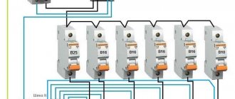
So, I'll start with the general concept. A three-phase SIP descends from a pole onto the facade of the house into a panel where an electric meter and 4 machines are installed:
- C32 at the entrance,
- C10 for street lighting and
- 2 pcs. C25 for cables to the 1st and 2nd floors, where distribution panels are installed.
Input panel with machines and counter
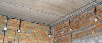
The cables from the input panel are VVG 5x4.0, running in black corrugation along the walls and through the ceiling.
The grounding is done like this: 4 2-meter pins along the bay window, connected by welding to each other with 8mm fittings, everything is connected to the street panel with a stranded wire of 4 mm2, and then with “power” cables to the panels of the 1st and 2nd floors.
Convenience and comfort
Next we look at it from an ergonomic point of view.
Items from this list do not apply to critical faults requiring urgent repairs: – places with insufficient lighting;
When thinking about a future project, keep in mind that one light bulb per room is usually not enough (unless it is a toilet or bathroom). Any lighting must have its own working scenario. Installing backlighting simply because you want to is short-sighted (you won’t use it anyway, but money and time have already been spent). In terms of ergonomics and lighting, I highly recommend the site houzz.ru, Articles section. There is no separate section for electrical work, so you will have to search.
– switches located in inconvenient places;
– inconveniently located sockets (the website houzz.ru also has about sockets) or insufficient number of sockets (you have to use a tee);
– Do you often use power tools outdoors? Is the extension cord that is pulled from the outlet in the house getting in the way? Install an outdoor waterproof outlet that is switched off by a separate circuit breaker. Please note that on some models, the covers that cover the sockets no longer stay in place over time. Choose a place for an outdoor outlet that will be 100% protected from precipitation, and even better, from the sun. Electrical insulating materials are either non-flammable or UV resistant.
– think about options for the future: perhaps the house needs a separate line for an electric stove, hood, refrigerator, heater, pump or boiler.
Even if you don’t see the point now, leave free space when designing the electrical panel (for circuit breakers, voltage stabilizers, terminal blocks and automation), the input cable should also be selected with a reserve cross-section;
Load calculation
A residential private house, the electricity supply of which can be provided through either a single-phase or a three-phase network, will, of course, be equipped with a variety of electrical appliances. In order to calculate the load on the lines, you should add their power and divide by the voltage. The result will be the required current strength. Knowing it, using special tables you can determine whether the network is overloaded and what cable is needed for wiring. When performing calculations, you should take into account the power of not only existing electrical appliances, but also those planned for purchase in the future.
For some very powerful household appliances, for example, a washing machine, boiler or electric stove, it is best to install a separate cable. Often a separate line is provided to office equipment. In the case of using any professional equipment in a garage or outbuilding, as already mentioned, three-phase power supply to a private home is used.
Grounding and lightning protection
Grounding is the connection of a part of an electrical network or equipment to a grounding device (ground electrode).
Diagram of one of the grounding systems
The ground electrode is a conductive part in contact with the ground; it can be made in the form of a metal rod or a complex of metal elements of complex shape.
The quality of grounding is determined by the resistance value of the grounding device, which can be reduced by increasing the area of the grounding conductors or the conductivity of the medium. The electrical resistance of the grounding device is determined in the project in accordance with the requirements of the Electrical Installation Rules (PUE).
The grounding circuit is shown in the figure below. It is installed in a development-free area of the site.
Ground loop
The following are subject to grounding:
- household electrical appliances with a unit power exceeding 1.3 kW;
- metal bodies of bathtubs and shower trays (they must be connected by metal conductors to water supply pipes);
- metal housings of lamps built-in or installed in suspended ceilings, which are made using metal;
- metal housings of household air conditioners.
Electrical equipment that has the characteristics listed below is also subject to grounding.
Electrical equipment to be grounded
To ground household appliances, it is advisable to use natural grounding conductors.
Natural grounding
Grounding switches should be installed before electrical installation work begins. Work on connecting foundation reinforcement with wall reinforcement must be carried out by a construction organization. The connection of grounding conductors to pipelines must be carried out either by welding or using a clamp. If it is impossible to use natural grounding conductors, artificial ones are used, for example, a grounding loop, which serves both for grounding electrical appliances in the house and for lightning protection (Fig. a, b ).
Connection of the ground electrode with the main ground bus (GZSh):
- a - through a grounding loop;
- b - using a prefabricated pin.
Lightning protection is a system of devices that ensures the safety of a building during electrical discharges in the atmosphere. Its main task is to change the trajectory of lightning discharges and extinguish its energy.
Lightning protection includes:
- lightning rod - a device that receives a lightning discharge;
- down conductor—electric discharge distribution elements;
- grounding switch - a device for extinguishing an electric discharge.
There are several lightning protection schemes based on different types of lightning rods:
- rod lightning rod - a metal rod connected by cables to a grounding conductor (Fig. a );
- spatial grid installed on the roof of the house, which distributes and extinguishes the discharge in the event of a direct lightning strike (Fig. b );
- tension system, which is similar to the operating diagram of a lightning rod, with the conductors stretched along the perimeter of the protected area (Fig. c ).
Lightning rod diagrams:
- a - rod;
- b - type of spatial cell;
- c - based on a tension system.
All of the above structures are made of steel rods, ropes or steel mesh with a diameter of at least 6 mm. The elements in the nodes are connected by welding.
The most common design is rod lightning rods. They are the most reliable and easiest to manufacture.
Lightning rods based on a tension system are used when constructing roofs of complex shapes. Using a lightning rod like a spatial cage is more expensive because it requires more material, plus it is more difficult to install on the roof. This design is advisable if the roof of the house is higher than other objects around it within a radius of 50 m.
How to get permission to connect
So, you have decided on the number of phases, the type of additional power supplies, etc. What's next? In what order is a private house connected to power lines? The power supply to country buildings is controlled by the network supply company in whose area of responsibility they are located. You will need to contact its specialists and collect the necessary package of documents. Their list should be found out in advance.
After receiving the documents, the network company will prepare technical conditions for power supply to a private home. Most likely, they will have to be coordinated with various related organizations. Next, a contract is concluded. After the network is installed, a representative of the network organization comes to the site and checks it for compliance with the requirements set out in the technical specifications. The inspection is carried out with the participation of all interested parties. Next, Rostechnadzor issues a permit to operate the network.
What kind of wiring should be done - hidden or open?
The advantages of hidden wiring are obvious. All wires and electrical fittings (socket boxes, distribution boxes) are hidden from view in grooves and sockets made in building structures and “camouflaged” with finishing, and only decorative frames remain outside. But this solution also has its downsides. If it is necessary to move, for example, an outlet to a more convenient location, you will need to dismantle the finishing, lay a new channel, reinstall the fittings and carefully hide all “traces of interference.” In addition, if the house is wooden, you will need to ensure that the wiring meets increased safety requirements. In the case of open wiring, their presence in the interior will have to be played up using various design techniques, but any “relocation” of the same outlet will not cause any problems.
Future plans
That's all for now. The whole winter is ahead for designing the circuit and electrical panel.
I want to talk about design. IEK has information for designers in its catalog (I don’t know about other manufacturers, for example, I didn’t find this from Schneider Electric or ABB). These are files in dwg (AutoCad) and step (Unigraphics) formats. This makes development very easy.
Design by IEK
Unfortunately, not every catalog item has such a rich set of files, but you can always find something very close in size. Some manufacturers even have proprietary programs for designing shields.
That's all for now. We wish Lena good luck! The most interesting things are yet to come!
I remind you that the article is competitive and takes part in voting. To find out how things are going with the Competition right now, follow the link.
