The controller is made in a SOP-8 housing, has a metal heat sink on the bottom surface that is not connected to contacts, and allows you to charge the battery with a current of up to 1000 mA (depending on the current-setting resistor). Requires a minimum of attachments. In fact, TP4056 is a more sophisticated modification of the TP4054 chip.
TP4056 automatically completes the charging cycle when its voltage reaches 4.2V and the charging current decreases to 1/10 of the programmed value. The module has an indication of the charging process. At the moment of charging, the red LED lights up, and when the battery is fully charged, the green LED lights up, while the red one goes out.
In addition to the TP4056 charging controller, two chips DW01 (protection circuit) and ML8205A (double MOSFET switch) are added to the board; they are used to protect the battery from overdischarge, overcharge, overload and short circuit.
The TP4056 module is ideal for portable devices. If an Arduino project requires full charging of Li-ion batteries with the ability to connect a load and with combustion protection, then this charge board will completely cope with this task.
- 1 TP4056 Specifications
- 2 Description of module pins
- 3 Schematic diagram of the module on TP4056
- 4 Connection diagram TP4056
- 5 Charging process
- 6 Charging current setting
- 7 Materials
- 8 Buy TP4056 on AliExpress
- 9 Similar posts
TP4056 Specifications
- Controller used : TP4056 and DW01 to protect the battery from overdischarge and overcharge;
- Charging mode : linear 1%;
- Charging current : up to 1A (configurable);
- Charging Accuracy: 1.5%;
- Input voltage : 4.5 - 5.5V;
- Full charge voltage : 4.2V;
- Indicators : red - charging, green (blue in some versions) - charge complete;
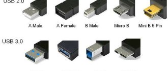
- Input connector : mini USB, MicroUSB or contacts for soldering wires;
- Temperature range : -10 to +85 degrees C;
- Reverse polarity protection : no;
- Overcharge protection : 4.30±0.050 V ;
- Overdischarge protection : 2.40±0.100 V;
- Weight : 5 g;
- Board dimensions : 25 × 17 × 4 mm.
Battery charge measurements
To study the battery charging process, the following measuring circuit was implemented:
The graph obtained with its help is presented in the following picture. For convenience in blue , and in red . In this case, the time is indicated in seconds.
6000 seconds correspond to 100 minutes, or in a more familiar form it is 1 hour 40 minutes. Accordingly, fully charging the battery took about 6 hours. With a battery capacity of 3000 mAh, the average charge current can be considered equal to 500 mA.
The graph clearly shows all three charging phases described above. The circuit works as expected. There is a small variation in the final voltage between different instances of modules, but it is not critical.
It is worth noting that any measurement of a physical quantity is only an attempt to approximate the true value. You should not pay attention to small teeth; their nature can be caused by both the unevenness of the ADC and the nonlinearity of the module. Which is not at all critical.
In any case, the resulting dependence perfectly satisfies all the rules of battery charging.
Description of module pins
| Conclusion | Description |
| IN+ | Vcc/Power |
| IN- | GND / Common |
| OUT+ | Load "+" |
| OUT- | Load "-" |
| BAT+ | To the "+" of the battery |
| BAT- | To "-" battery |
Operating principle of the board
The largest electronics manufacturers are engaged in the production of charging controllers: Panasonic, Samsung, Sony, LG, ATL, HYB, Sanio. They distribute the circuits to other manufacturers, who pass them off as their own products.
The operating principle of the microcontroller is to ensure normal operating conditions for the battery, in accordance with its basic technical characteristics:
Operating principle of the controller.
- maximum voltage – 4.2V (the board protects against minor overcharging, which has a detrimental effect on the overall service life);
- minimum voltage – 2.75V (if the charge level of the 18650 battery drops below 2V, it will be irrevocably damaged);
- minimum temperature - charging and using the battery at 20°C and below is not allowed (the battery can suddenly lose capacity, go into overdischarge, and as a result its consumer properties will significantly deteriorate);
- maximum temperature - operation and storage of Li-Ion batteries at temperatures above +40 is prohibited (lithium-ion batteries are exposed to high temperatures and may smoke, ignite, or explode);
- charging speed - the timing is affected by the current strength and battery capacity. The maximum capacity of a reusable battery marked 18650 is 3600 mAh. That is, by charging 1A you can replenish the charge in 1 hour, 2A current - 30 minutes, 15A current - 4 minutes.
The marking of a 18650 lithium-ion battery means its dimensions - that is, the length of the battery is 65 mm, the diameter is 18 mm.
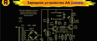
Schematic diagram of the module on TP4056
The circuit (without protection) is almost identical to the circuit from the datasheet, with the exception of connecting the battery temperature sensor. If necessary, you can remove the temperature sensor input with a separate wire by soldering it to the tab and cutting it off from GND. Or by lifting the paw above the board and soldering it.
The protection circuit based on DW01A (from the specification) is as follows:
Below is a typical connection of TP4056, protection based on DW01A and S-8205A mosfets.
Lithium battery charge control chips
Today there are microcircuits that are a ready-made charge controller for lithium batteries. One of such microcircuits is TP4056 (). The circuit diagram of the lithium battery charge controller on the TP4056 is as follows:
However, if you decided to implement it, then I hasten to disappoint you. The effort, time and money spent will be many times greater than the cost of a finished module built according to exactly the same circuit and even enhanced with more powerful output transistors.
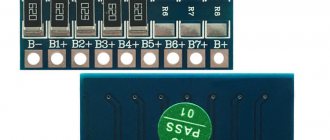
Connection diagram TP4056
Connect to charging via a standard microUSB (or miniUSB) connector or via duplicate contacts “ + ” and “ - “. The battery (without built-in discharge protection) is connected to the “ B+ ” and “ B- ” contacts. The load is connected to the “ OUT+ ” and “ OUT- ” contacts (when charging the battery, it is advisable to disconnect the load if it is not designed for a voltage of 4.2 V).
If you reverse the polarity of the power supply, the microcircuit gets very hot and dies; if you reverse the polarity of the battery, then again the TP4056 heats up and dies after a while. You shouldn’t supply more than 8 volts to the input either. The optimal supply voltage is 5 V, although approximately 4.5 to 8 V can be supplied. The higher the supply voltage, the more the TP4056 will heat up since the voltage is converted linearly.
How the module heats up
During charging, when the current is 1 ampere, the module gets quite hot. It is worth considering this fact when using the module in a closed device. Thus, in the open air, the temperature of the module reached values of more than 70 degrees ( according to the thermocouple ).
If the module is installed in a closed case, it is advisable to reduce the maximum charge current to 500-700 mA. But you still shouldn’t attach it to thermal glue.
The module itself has overheating protection. So, when the module overheats, it begins to limit the output current. So he most likely will not die from overheating. But you shouldn’t rely entirely on protection))
Charging process
The charging process consists of several stages:
- Monitoring the voltage of the connected battery (continuously);
- Charging with a current of 1/10 from the one programmed by the resistor Rprog (100mA at Rprog = 1.2k) to a level of 2.9 V (if required);
- Charging with maximum current (1000mA at Rprog = 1.2k);
- When the battery reaches 4.2 V, the voltage stabilizes at 4.2 V. The current drops as it charges;
- When the current reaches 1/10 of the one programmed by the resistor Rprog (100mA at Rprog = 1.2k), the charger turns off. Go to step 1.
The red LED signals charging, the green LED (blue in some versions of the boards) indicates that charging is complete.
Reasons for blocking a li-ion 18650 battery by the controller
The main reason is the occurrence of a short circuit due to exceeding the maximum permissible voltage inside the battery. The microcircuit breaks the electrical circuit. To unlock the battery, just charge it.
The second reason is deep battery discharge. In case of a deep non-critical discharge, the battery can be unlocked using a charger.
If discharged to a critical state, the device will not turn on: internal chemical processes lead to the formation of metallic lithium crystals, which create dangerous contact between the positive and negative poles, leading to an explosion.
Setting the charging current
The controller has a good CC/CV profile and can be adapted to many different charging configurations and Li-ion battery types. The rated charging current can be changed by selecting the resistor Rprog (default: 1A).
| Resistor (kOhm) | Charge current (mA) |
| 30 | 50 |
| 20 | 70 |
| 10 | 130 |
| 5 | 250 |
| 4 | 300 |
| 3 | 400 |
| 2 | 580 |
| 1.66 | 690 |
| 1.5 | 780 |
| 1.33 | 900 |
| 1.2 | 1000 |
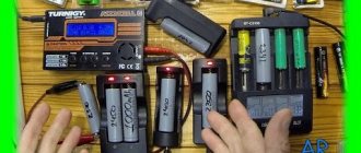
Module performance measurement
We will measure the following:
- Charging process - let's see how the charging current changes depending on the voltage on the battery.
- Discharge , or rather the ability of the module to continuously supply current to the load, as well as the ability to cut off the battery upon reaching the discharge threshold.
For these purposes we need a voltmeter and an ammeter. But I’m a lazy person, and measuring by hand in our age is a monkey’s work. Therefore, the PIC18F4550 microcontroller was called to help. It can communicate with a computer via USB and has a 10-bit ADC on board.
The ammeter and voltmeter are shown below conventionally. Both the voltmeter and the ammeter are implemented using differential amplifiers . To measure current, a low-resistance resistor is used, the voltage difference from the terminals of which is measured by a differential amplifier. A separate article was recently devoted to this method of measuring current .
From the differential outputs Amplifiers send the signal to the ADC of the microcontroller. The ADC voltage step is about 5 mV, which is more than enough for such measurements. To reduce the error as much as possible, the data arriving over 10 seconds was averaged (200 incoming values each).
All torture was carried out using a Sony VTC6 18650 battery. This battery has a capacity of 3000 mAh. The maximum output current of the battery can reach 30A.
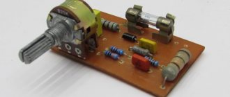
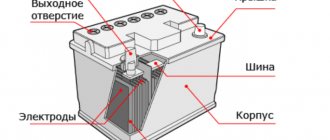
What does the battery controller consist of?
The electrical circuit is very simple and does not require deep knowledge of circuit design. Although manufacturers of expensive smartphones are trying to improve it, the design principle remains the same for everyone.
On the printed circuit board of the battery controller in most cases the following are placed:
- • resistor in the power circuit,
- • storage capacitor,
- • the protection controller itself in the form of a microcircuit,
- • resistor in the protection circuit,
- • thermistor,
- • MOSFET transistors.
In some cases, the controller is wired into three contacts instead of two - then, in addition to the traditional “plus” and “minus”, the manufacturer uses the so-called “information contact”.
DC/DC converters for solar panels
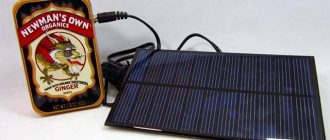
For most battery-powered mobile devices, the charger is designed as a stand-alone device for household AC power. That is, in any case, an AC/DC converter is required to generate a DC input voltage for the battery charging microcircuit. STMicroelectronics offers a wide range of such converters, as well as proven network adapter design technology. However, network chargers, although the most common, are not the only possible solution. Solar energy stored in solar panels can be used as an energy source. The STMicroelectronics product range includes DC/DC converter microcircuits for solar cells using the MPPT (Maximum Power Point Tracking) algorithm. Without going into specific details, we note that today MPPT technology is the most advanced and efficient technology for solar charge controllers. Calculating the maximum charging efficiency point from a solar module allows you to increase the efficiency of solar energy generation by up to 25...30% compared to other types of controllers [6]. STMicroelectronics currently produces two microcircuits - SPV1020 and SPV1040 . The first works with a chain of series-connected solar cells with an output voltage in the range of 6.5 ... 40 V. The second, as a rule, with a single battery with a voltage of up to 5.5 V. STMicroelectronics has also released a demo board STEVAL-ISV012V1, which includes MPPT DC/DC converter SPV1040 and charge chip L6924D . Figure 8 shows a demo board.
Rice. 8. Solar charger demo board STEVAL-ISV012V1
The material [7] indicates that the total efficiency of such a combination is approximately 85% (for SPV1040 - 94%, for L6924D - 90%).
Operating modes of lithium batteries
There are 2 main modes of using lithium batteries:
- Buffer – for example, in modern uninterruptible power supplies. In this case, the battery is constantly fed from the mains, and during power outages, it releases the accumulated charge to the equipment connected to it. When the power supply from the network is restored, the battery is recharged again and is in constant readiness for further use.
- Cyclic - implies an alternation of charge-discharge phases, when after the passive phase of charge recovery there is a long phase of active operation. In this mode, batteries for electric bicycles and other types of personal electric transport, forklifts, floor scrubbers, electric vehicles, motor boats, mobile coffee machines and other equipment operate. The service life of such batteries is measured not in years, but in the number of deep discharge cycles (up to 80%) and subsequent charge.
Lithium-ion batteries are successfully used in both buffer and cyclic mode. If the operation of the battery involves harsh conditions and frequent deep discharges, lithium iron phosphate batteries (LiFePO4) cope best with such tasks. In particular, they are used to power boat electric motors, warehouse and cleaning equipment, e-bikes and other types of electric vehicles.