When batteries are connected in series, there is a scatter in the parameters of the products, which does not allow maintaining the required output voltage. The problem occurs due to uneven charging of the cells. To eliminate the defect, a lithium battery balancing board is used, which ensures uniform charging of products and prevents overcharging of battery bank elements.
Learn about the purpose of the lithium battery balancing board.
Principles of charging lithium-ion batteries
The first thing to note is that a fully charged lithium battery has a nominal open circuit voltage of 3.7 volts. In this case, it must be charged to 4.2 volts. There is no contradiction here - you actually need to charge up to the specified threshold, and after charging is complete, due to self-discharge, the output level will quickly (within a few hours at most) drop to 3.7 volts. After this, the self-discharge process will slow down sharply, and the battery will stably maintain its 3.7 volts.
Unlike many types of batteries, batteries made using Li-ion technology should ideally be charged in two stages:
- charging with a stable current (to maintain it, you need to constantly increase the voltage);
- the second stage is recharging with a stable voltage (the current drops).
Professional memory devices work according to a similar algorithm.
Classic charge graph for lithium-ion batteries.
This and subsequent graphs do not indicate the preliminary stage, which is used for deeply discharged elements. Its meaning is that such a battery reaches its minimum state with a low current, and then the battery is charged as usual.
In practice, the principle of recharging the battery with current pulses of constant amplitude is often used. When a certain cell voltage level is reached (usually 4.15 volts), the charger turns off. The idle voltage of an undercharged battery quickly drops, the charger sees this and again supplies a current pulse until the threshold of 4.15 volts is reached. With each pulse, the battery is recharged, and the decline occurs more and more slowly. Also, the next and subsequent current pulses will be shorter and shorter. Due to this, pseudo-voltage stabilization is realized within certain limits. The advantage of this algorithm is that recharging is impossible in principle , and you can keep the battery in the charger for as long as you like - if it self-discharges, it will be periodically recharged.
Pulse current charging.
Another way to implement the second stage is charging with stepped current. At first glance, this algorithm is complicated.
Charging with step current.
But it can be degenerated to one stage - the voltage supplied to the element simply decreases. The charging current remains stable, although its amplitude decreases. This principle has the right to life in inexpensive chargers. The second stage takes place, in contrast to very simple chargers, in which only the first stage is implemented. Although nothing bad happens in this - the battery capacity is simply not fully used. In addition, there is a widespread but unsubstantiated statement that lithium-ion cells only need to be charged to 90%. No one has provided evidence of this; to believe it or not is everyone’s personal choice.
Charging with single-stage current.
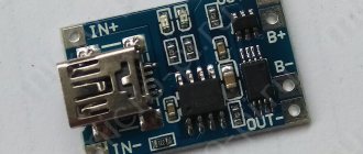
Operating principle of the TP4056 module with and without protection
Lithium batteries are very demanding when it comes to charging methods. They cannot be charged above 4.2 V and it is not advisable to charge them with a higher current; the lower the charging current, to reasonable limits, the longer the batteries will last. The TP4056 controller just ensures the correct charging of lithium batteries using the CC/CV method. CC means constant current charge and CV means constant voltage charge.
TP4056 modules with and without protection charge lithium batteries using the CC/CV method, providing a constant specified charge current at the beginning of charge, and a constant charge voltage of 4.2V at the end of charge. Additionally, the controller implements the TC method, in which a heavily discharged battery is charged with a current of 1/10 of the rated current until the battery reaches a voltage of 2.9 V.
By default, all TP4056 charge modules are configured with a maximum charge current of 1 A. If the voltage on the battery is more than 2.9 V, then the battery charge is immediately equal to 1 A, and remains at this level until almost fully charged. At this moment, the red LED on the board lights up. When the battery voltage approaches the nominal voltage, the charging current begins to decrease, while maintaining a constant voltage at the charger output of 4.2 V. The current and voltage charging curves of lithium batteries using the CC/CV method can be seen in the graph below.
When the charging current drops to 100 mA, the TP4056 controller stops charging. At this moment, the red LED goes out and the blue LED lights up.
The TP4056 module with protection also monitors the discharge of the lithium battery. The battery is protected from short circuits, and if you close the output contacts of the board, the load will simply be disconnected from the battery until the short circuit disappears. During battery discharge, the discharge current and voltage are monitored. The discharge current is limited to 3 A, if the flowing current becomes greater, the load is disconnected from the battery. When the voltage at the battery terminals drops below 2.5 V, the load is also disconnected from the battery, protecting it from overdischarge.
What you need for a homemade memory
First of all, you will need to select a charging scheme for 18650 cells. It is selected according to the necessary parameters, as well as the availability of parts. Secondly, the skills of reading circuit diagrams, making printed circuit boards at home (or at least ordering them from China, which is not so expensive now), soldering microcircuits and other elements, finding errors and malfunctions. If you don’t have this, you shouldn’t even read what you will need:
- radioelements according to the diagram;
- soldering iron with a set of consumables;
- board or blank for it and accessories for self-production.
You will also need a case for installing batteries for charging (it makes it more convenient to connect the battery to the charger).
Plastic case for connecting 18650 battery.
It is better to develop skills separately, and then take on the production of these devices. They are not very difficult, but require a conscious approach.
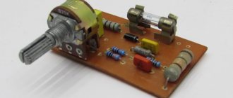
Charge controller circuits
Charger for LM317.
A simple homemade memory can be assembled using the widespread and inexpensive LM317 microcircuit. In this case, it is connected according to the voltage stabilizer circuit, and the battery is charged by the falling current. This algorithm does not allow full use of the battery's capabilities, and this is the main drawback of the scheme. Another drawback is that voltages below 8 volts cannot be supplied to the circuit. Therefore, it will not be possible to power the memory from the USB port.
During the process, the current is monitored in the form of a voltage drop across resistor R1. As soon as it decreases to a certain level, transistor VT1 closes and the LED goes out, signaling the end of charging. The process does not stop, so you need to monitor the condition yourself. You can upgrade the circuit by turning on a relay instead of the LED, which, when turned off, opens the power circuit with its contacts.
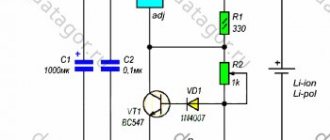
The charger is somewhat more complicated, allowing you to implement a pulse current charging algorithm without any controllers.
Charger circuit with pulse recharging function.
At the first stage, the battery is charged with a stable current, the value of which is determined by the supply voltage and the value of the resistor RD. When the voltage reaches the threshold of 4.15 volts, the comparator is triggered and transistor VT1 is turned off. The voltage across the element will soon drop below the threshold, and the transistor will open again. This procedure will continue cyclically, but as the charge progresses, the pauses will become longer and the pulses shorter. As a result, the battery will be charged to a voltage of 4.15 volts, which is set by resistor R1.
Analysis of the circuit shows that it can be easily simplified without reducing functionality. So, instead of a transformer with a midpoint and a rectifier, you can take any power source with a voltage of 5 volts (there is no need to increase the voltage much, the elements of the power circuit will heat up, bringing the thermal death of the universe closer). The transistor can be replaced with a bipolar one (the domestic KT827 is also suitable).
Simplified memory diagram.
The voltage detector can be replaced with KIA742, KIA719, KIA739. As a result, the diagram will take the following form.
You can also use specialized microcircuits specifically designed to create such chargers. One of them is MCP73831.
Charging algorithm implemented on the MCP73831 (using the example of a battery with a capacity of 180 mAh).
It supports correct two-stage charging mode. The current is set by the value of the resistor connected between pins 5 and 2. The only drawback is the highest current that can be removed from the microcircuit - 500 mA. This is not always enough; high-capacity cells will take a long time to charge.
Typical connection diagram for MCP73831.
You can also assemble the charger using other specialized microcircuits specially designed for a similar purpose. In addition to the classic MAX1555, these can be:
- LP2951;
- LTC4054;
- TP4056;
- LTC1734;
- MCP73812;
- NCP1835;
- other microcircuits.
Each element has its pros and cons. To understand them and make the right choice, you need to read the datasheets.
General information about lithium-ion batteries
Lithium batteries appeared relatively recently, but have already firmly taken a leading position in the power supply of autonomous devices. Structurally, such a power source consists of two electrodes - a cathode and an anode. The first is made of one or another lithium compound (usually cobalt-lithium or lithium ferrophosphate), the second is made of graphite. The electrodes are immersed in an anhydrous electrolyte solution. There are different form factors and sizes of batteries of this type. The most common form factors for lithium-ion batteries are cylindrical and rectangular.
Rectangular elements can be seen in devices of small thickness - mobile phones, smartphones, tablets, etc. Typically, batteries of this shape use polymer material as an electrolyte, and the batteries themselves are called lithium-polymer.
The output voltage of all lithium batteries varies from 4.2 to 2.5 V depending on the state of charge and averages 3.7 V. Electrical capacity varies - from tens of milliamps per hour (mAh) to tens of amperes per hour (Ah). Depends on the purpose of the power source and its size.
Expert opinion
Alexey Bartosh
Specialist in repair and maintenance of electrical equipment and industrial electronics.
Ask a Question
Important! We are talking about single batteries. Batteries made up of several elements can have any voltage and any capacity. For example, electric vehicle batteries have a voltage of up to 380 V with a capacity of hundreds of kilowatt-hours, and a laptop battery produces 12.6 V.
The service life of a lithium battery depends on operating conditions and is usually 2–3 years with a number of charge/discharge cycles of up to 600 for lithium-ion batteries and up to 900 for lithium-polymer batteries. The main qualities of batteries of this type:
- high energy density per unit mass;
- low self-discharge;
- no memory effect;
- do not require maintenance;
- lose performance when overcharged and deeply discharged;
- Explosion hazard if overheated.
What is the difference between a charge controller and a protection circuit?
Some users periodically have a question, put in the title of the section - why do we need a charge controller if there is a protection circuit (individual or general in the form of a balancing board). The fact is that these devices solve different problems :
- the protective module protects the element from overcharging, prevents it from going into a deep discharge, and turns off the battery when the permissible temperature is exceeded;
- The charge controller forms the correct mode of energy replenishment - stabilizes the current at a given level, carries out additional charging according to various algorithms.
And confusion may arise due to the fact that there are cases when some of the functions of these devices are duplicated. Thus, overheating protection can be built into both the protection board and the charge controller. And both the built-in board (disabling the battery) and the charger (completing the process of replenishing energy) can protect against overcharging.
Characteristics of TP4056 modules with and without battery protection
TP4056 modules with and without protection differ only in the battery protection function, and the characteristics regarding the charging of lithium batteries are identical. Naturally, their dimensions are also different.
TP4056 Unprotected Module Specifications: Recommended Input Voltage: 5 V Input Voltage Range: 4.5 – 8 V Default Maximum Charge Current: 1000 mA Charge Stop Voltage: 4.2 V (± 1%) Board Size: 23 mm x 17 mm LED Statuses: red – charge, blue (green) – charge complete
Characteristics of the TP4056 module with protection: Recommended input voltage: 5 V Input voltage range: 4.5 - 8 V Default maximum charge current: 1000 mA Battery cut-off voltage when discharging: 2.5 V Maximum permissible discharge current: 3 A Charge stop voltage: 4.2 V ( ± 1%) Board size: 27 mm x 17 mm LED statuses: red – charging, blue (green) – charging complete
General assembly principle for any 18650 charger
First of all, you need to make a board. You can develop it yourself (in programs like Sprint LayOut), or you can find a ready-made one on the Internet. Then there are two ways:
- Make a board using the LUT method or other home technology.
- Order a board in China.
In the second option, the board will obviously be of better quality, but it will cost more, and you will have to wait more than one day.
When assembling a charger for 18650 batteries on specialized microcircuits, you must keep in mind that their cases are often subminiature, and soldering such elements requires special skills.
Charging Recommendations for 18650 Lithium Batteries
First of all, lithium-ion cells should not be allowed to be deeply discharged. This applies to a greater extent to unprotected batteries, but batteries with a protection board are also not completely protected from this problem. Yes, the circuit will turn off the element when the lower threshold is reached, but it will not cancel self-discharge. Therefore, when storing unused batteries, it is better to periodically recharge them. If a deep discharge cannot be avoided, you can try to bring the battery to a voltage of 2.4 volts with a low charging current (0.1..0.2 of the capacity). If it works, you can continue charging in the usual way; if not, the element will have to be disposed of.
You also need to be careful about recharging issues. Elements marked Protected will turn off when the upper limit is reached, but banks without a protection board will continue to charge. And the extinguishing of the charger LED does not solve the problem - in most cases it is just an indication that the rated voltage has been reached, and the charger does not turn off. Considering the fire hazard of lithium-ion batteries and the problems with extinguishing them, you must independently monitor the end of the process and turn off the charger from the network in time.
Homemade chargers for lithium-ion batteries work no worse than industrial ones. But only if they are assembled and configured by a competent user who understands the processes occurring during energy replenishment.