It's no secret that Li-ion batteries do not like deep discharge. This causes them to wither and wither, and also increase internal resistance and lose capacity. Some specimens (those with protection) can even plunge into deep hibernation, from where it is quite problematic to pull them out. Therefore, when using lithium batteries, it is necessary to somehow limit their maximum discharge.
To do this, special circuits are used that disconnect the battery from the load at the right time. Sometimes such circuits are called discharge controllers.
Because The discharge controller does not control the magnitude of the discharge current; strictly speaking, it is not a controller of any kind. In fact, this is an established but incorrect name for deep discharge protection circuits.
Contrary to popular belief, the built-in batteries (PCB boards or PCM modules) are not designed to limit the charge/discharge current, or to timely disconnect the load when fully discharged, or to correctly determine the end of charging.
Firstly,
Protection boards, in principle, are not capable of limiting the charge or discharge current. This should be handled by the memory department. The maximum they can do is turn off the battery when there is a short circuit in the load or when it overheats.
Secondly,
Most protection modules turn off the li-ion battery at a voltage of 2.5 Volts or even less. And for the vast majority of batteries, this is a very strong discharge; this should not be allowed at all.
Third,
The Chinese are riveting these modules in the millions... Do you really believe that they use high-quality precision components? Or that someone tests and adjusts them before installing them in batteries? Of course, this is not true. When producing Chinese motherboards, only one principle is strictly observed: the cheaper, the better. Therefore, if the protection disconnects the battery from the charger exactly at 4.2 ± 0.05 V, then this is more likely a happy accident than a pattern.
It’s good if you got a PCB module that will operate a little earlier (for example, at 4.1V). Then the battery simply won’t reach ten percent of its capacity and that’s it. It is much worse if the battery is constantly recharged, for example, to 4.3V. Then the service life is reduced and the capacity drops and, in general, may swell.
It is IMPOSSIBLE to use the protection boards built into lithium-ion batteries as discharge limiters! And as charge limiters too. These boards are intended only for emergency battery disconnection in case of emergency situations.
Therefore, separate circuits for limiting charge and/or protecting against too deep discharge are needed.
We looked at simple chargers based on discrete components and specialized integrated circuits in. And today we’ll talk about the solutions that exist today to protect a lithium battery from too much discharge.
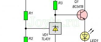
To begin with, I propose a simple and reliable Li-ion overdischarge protection circuit, consisting of only 6 elements.
The ratings indicated in the diagram will result in the batteries being disconnected from the load when the voltage drops to ~10 Volts (I made protection for 3 series-connected 18650 batteries in my metal detector). You can set your own shutdown threshold by selecting resistor R3.
By the way, the full discharge voltage of a Li-ion battery is 3.0 V and no less.
A field chip (like the one in the diagram or something similar) can be dug out from an old computer motherboard; usually there are several of them there at once. TL-ku, by the way, can also be taken from there.
Capacitor C1 is needed for the initial startup of the circuit when the switch is turned on (it briefly pulls the gate T1 to minus, which opens the transistor and powers the voltage divider R3, R2). Further, after charging C1, the voltage required to unlock the transistor is maintained by the TL431 microcircuit.
Attention! The IRF4905 transistor indicated in the diagram will perfectly protect three lithium-ion batteries connected in series, but is completely unsuitable for protecting one 3.7 Volt bank. It is said how to determine for yourself whether a field-effect transistor is suitable or not.
The downside of this circuit: in the event of a short circuit in the load (or too much current consumed), the field-effect transistor will not close immediately. The reaction time will depend on the capacitance of capacitor C1. And it is quite possible that during this time something will have time to burn out properly. A circuit that instantly responds to a short load under load is presented below:
Switch SA1 is needed to “restart” the circuit after the protection has tripped. If the design of your device provides for removing the battery to charge it (in a separate charger), then this switch is not needed.
The resistance of resistor R1 must be such that the TL431 stabilizer reaches operating mode at a minimum battery voltage - it is selected in such a way that the anode-cathode current is at least 0.4 mA. This gives rise to another drawback of this circuit - after the protection is triggered, the circuit continues to consume energy from the battery. The current, although small, is quite enough to completely drain a small battery in just a couple of months.
The diagram below for self-made monitoring of the discharge of lithium batteries is free from this drawback. When the protection is triggered, the current consumed by the device is so small that my tester does not even detect it.
Below is a more modern version of the lithium battery discharge limiter using the TL431 stabilizer. This, firstly, allows you to easily and simply set the desired response threshold, and secondly, the circuit has high temperature stability and clear shutdown. Clap and that's it!
Getting TL-ku today is not a problem at all, they are sold for 5 kopecks per bunch. Resistor R1 does not need to be installed (in some cases it is even harmful). Trimmer R6, which sets the response voltage, can be replaced with a chain of constant resistors with selected resistances.
To exit the blocking mode, you need to charge the battery above the protection threshold, and then press the S1 “Reset” button.
The inconvenience of all the above schemes is that to resume operation of the schemes after going into protection, operator intervention is required (turn SA1 on and off or press a button). This is the price to pay for simplicity and low power consumption in lock mode.
The simplest li-ion overdischarge protection circuit, devoid of all disadvantages (well, almost all) is shown below:
The principle of operation of this circuit is very similar to the first two (at the very beginning of the article), but there is no TL431 microcircuit, and therefore its own current consumption can be reduced to very small values - about ten microamps. A switch or reset button is also not needed; the circuit will automatically connect the battery to the load as soon as the voltage across it exceeds a preset threshold value.
Capacitor C1 suppresses false alarms when operating on a pulsed load. Any low-power diodes will do; it is their characteristics and quantity that determine the operating voltage of the circuit (you will have to select it locally).
Any suitable n-channel field-effect transistor can be used. The main thing is that it can withstand the load current without straining and be able to open at low gate-source voltage. For example, P60N03LDG, IRLML6401 or similar (see).
The above circuit is good for everyone, but there is one unpleasant moment - the smooth closing of the field-effect transistor. This occurs due to the flatness of the initial section of the current-voltage characteristic of the diodes.
This drawback can be eliminated with the help of modern element base, namely with the help of micro-power voltage detectors (power monitors with extremely low power consumption). The next circuit for protecting lithium from deep discharge is presented below:
MCP100 microcircuits are available in both DIP packages and planar versions. For our needs, a 3-volt option is suitable - MCP100T-300i/TT. Typical current consumption in blocking mode is 45 µA. The cost for small wholesale is about 16 rubles/piece.
It’s even better to use a BD4730 monitor instead of the MCP100, because it has a direct output and, therefore, it will be necessary to exclude transistor Q1 from the circuit (connect the output of the microcircuit directly to the gate of Q2 and resistor R2, while increasing R2 to 47 kOhm).
The circuit uses a micro-ohm p-channel MOSFET IRF7210, which easily switches currents of 10-12 A. The field switch is fully open already at a gate voltage of about 1.5 V, and in the open state it has negligible resistance (less than 0.01 Ohm)! In short, a very cool transistor. And, most importantly, not too expensive.
In my opinion, the last scheme is the closest to the ideal. If I had unlimited access to radio components, I would choose this one.
A small change in the circuit allows you to use an N-channel transistor (then it is connected to the negative load circuit):
BD47xx power supply monitors (supervisors, detectors) are a whole line of microcircuits with response voltages from 1.9 to 4.6 V in steps of 100 mV, so you can always choose them to suit your purposes.
A small retreat
Any of the above circuits can be connected to a battery of several batteries (after some adjustment, of course). However, if the banks have different capacities, then the weakest of the batteries will constantly go into a deep discharge long before the circuit operates. Therefore, in such cases, it is always recommended to use batteries not only of the same capacity, but preferably from the same batch.
And although this protection has been working flawlessly in my metal detector for two years now, it would still be much more correct to monitor the voltage on each battery personally.
Always use your personal Li-ion battery discharge controller for each jar. Then any of your batteries will serve you happily ever after.
How to choose a suitable field-effect transistor
In all of the above schemes for protecting lithium-ion batteries from deep discharge, MOSFETs operating in switching mode are used. The same transistors are usually used in overcharge protection circuits, short-circuit protection circuits, and in other cases where load control is required.
Of course, in order for the circuit to work as it should, the field-effect transistor must meet certain requirements. First, we will decide on these requirements, and then we will take a couple of transistors and use their datasheets (technical characteristics) to determine whether they are suitable for us or not.
Attention! We will not consider the dynamic characteristics of FETs, such as switching speed, gate capacitance and maximum pulsed drain current. These parameters become critically important when the transistor operates at high frequencies (inverters, generators, PWM modulators, etc.), however, discussion of this topic is beyond the scope of this article.
So, we must immediately decide on the circuit that we want to assemble. Hence the first requirement for a field-effect transistor - it must be of the appropriate type
(either N- or P-channel). This is the first one.
Let's assume that the maximum current (load current or charge current - it doesn't matter) will not exceed 3A. This leads to the second requirement - the field worker must withstand such current for a long time
.
Third. Let's say our circuit will protect the 18650 battery from deep discharge (one bank). Therefore, we can immediately decide on the operating voltages: from 3.0 to 4.3 Volts. This means that the maximum permissible drain-source voltage U ds
should be more than 4.3 Volts.
However, the last statement is true only if only one lithium battery bank is used (or several connected in parallel). If, to power your load, a battery of several batteries connected in series will be used, then the maximum drain-source voltage of the transistor must exceed the total voltage of the entire battery
.
Here is a picture explaining this point:
As can be seen from the diagram, for a battery of 3 18650 batteries connected in series, in the protection circuits of each bank it is necessary to use field devices with a drain-to-source voltage U ds > 12.6V (in practice, you need to take it with some margin, for example, 10%).
At the same time, this means that the field-effect transistor must be able to open completely (or at least strongly enough) already at a gate-source voltage U gs of less than 3 Volts. In fact, it is better to focus on a lower voltage, for example, 2.5 Volts, so that there is a margin.
For a rough (initial) estimate, you can look in the datasheet at the “ Gate Threshold
) is the voltage at which the transistor is on the threshold of opening. This voltage is typically measured when the drain current reaches 250 µA.
It is clear that the transistor cannot be operated in this mode, because its output impedance is still too high, and it will simply burn out due to excess power. Therefore, the cutoff voltage of the transistor must be less than the operating voltage of the protection circuit
. And the smaller it is, the better.
In practice, to protect one can of a lithium-ion battery, you should select a field-effect transistor with a cutoff voltage of no more than 1.5 - 2 Volts.
Thus, the main requirements for field-effect transistors are as follows:
- transistor type (p- or n-channel);
- maximum permissible drain current;
- the maximum permissible drain-source voltage U ds (remember how our batteries will be connected - in series or in parallel);
- low output resistance at a certain gate-source voltage U gs (to protect one Li-ion can, you should focus on 2.5 Volts);
- maximum permissible power dissipation.
Now let's look at specific examples. For example, we have at our disposal the transistors IRF4905, IRL2505 and IRLMS2002. Let's take a closer look at them.
Example 1 - IRF4905
We open the datasheet and see that this is a transistor with a p-type channel (p-channel). If we are satisfied with this, we look further.
The maximum drain current is 74A. In excess, of course, but it fits.
Drain-source voltage is 55V. According to the conditions of the problem, we have only one bank of lithium, so the voltage is even greater than required.
Next, we are interested in the question of what the drain-source resistance will be when the opening voltage at the gate is 2.5V. We look at the datasheet and don’t immediately see this information. But we see that the cutoff voltage U gs(th) lies in the range of 2…4 Volts. We are categorically not happy with this.
The last requirement is not met, so we reject the transistor
.
Example 2 - IRL2505
Here is his datasheet. We look and immediately see that this is a very powerful N-channel field device. Drain current - 104A, drain-source voltage - 55V. So far everything is fine.
Check the voltage V gs(th) - maximum 2.0 V. Excellent!
But let's see what resistance the transistor will have at a gate-source voltage = 2.5 volts. Let's look at the chart:
It turns out that with a gate voltage of 2.5V and a current through the transistor of 3A, a voltage of 3V will drop across it. In accordance with Ohm's law, its resistance at this moment will be 3V/3A=1Ohm.
Thus, when the voltage on the battery bank is about 3 Volts, it simply cannot supply 3A to the load, since for this the total load resistance, together with the drain-source resistance of the transistor, must be 1 Ohm. And we only have one transistor that already has a resistance of 1 ohm.
In addition, with such an internal resistance and a given current, the transistor will release power (3 A) 2 * 3 Ohm = 9 W. Therefore, you will need to install a radiator (a TO-220 case without a radiator can dissipate somewhere around 0.5...1 W).
An additional alarm bell should be the fact that the minimum gate voltage for which the manufacturer specified the output resistance of the transistor is 4V.
This seems to hint that the operation of the field worker at a voltage U gs less than 4 V was not envisaged.
Considering all of the above, we reject the transistor
.
Example 3 - IRLMS2002
So, let's take our third candidate out of the box. And immediately look at its performance characteristics.
N-type channel, let's say everything is in order.
Maximum drain current - 6.5 A. Suitable.
The maximum permissible drain-source voltage V dss = 20V. Great.
Cut-off voltage - max. 1.2 Volts. Still alright.
To find out the output resistance of this transistor, we don’t even have to look at the graphs (as we did in the previous case) - the required resistance is immediately given in the table just for our gate voltage.
Progress is moving forward, and lithium batteries are increasingly replacing the traditionally used NiCd (nickel-cadmium) and NiMh (nickel-metal hydride) batteries. With a comparable weight of one element, lithium has a larger capacity, in addition, their element voltage is three times higher - 3.6 V per element, instead of 1.2 V. The cost of lithium batteries has begun to approach conventional alkaline batteries, the weight and size are much higher less, and besides, they can and should be charged. The manufacturer says they can withstand 300-600 cycles. There are different sizes and choosing the right one is not difficult. The self-discharge is so low that they sit for years and remain charged, i.e. The device remains operational when needed.
Which batteries are not afraid of deep discharge?
Currently, car batteries can be distinguished that are truly not afraid of a possible deep discharge
If we talk about what exactly these “fearless” batteries are, then attention is focused on GEL and AGM technologies
It is in their case that the loss of charge will not be critical, and after charging the batteries they will be able to function normally for many more years.
It is because of this that salts practically cannot settle on the surfaces of the plates. But even here it was not possible to completely get rid of possible sulfation. It’s just that the number of charge-discharge cycles in which sulfation actually makes itself felt has been increased several times.
"C" stands for Capacity
A designation like “xC” is often found. This is simply a convenient designation of the charge or discharge current of the battery with shares of its capacity. Derived from the English word “Capacity” (capacity, capacity). When they talk about charging with a current of 2C, or 0.1C, they usually mean that the current should be (2 × battery capacity)/h or (0.1 × battery capacity)/h, respectively. For example, a battery with a capacity of 720 mAh, for which the charge current is 0.5 C, must be charged with a current of 0.5 × 720 mAh / h = 360 mA, this also applies to discharge.
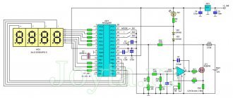
You can make a simple or not very simple charger yourself, depending on your experience and capabilities.
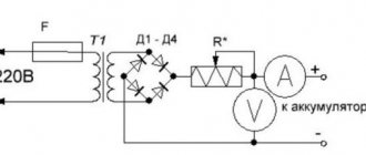
Circuit diagram of a simple LM317 charger
Rice.
5. The application circuit provides fairly accurate voltage stabilization, which is set by potentiometer R2. Current stabilization is not as critical as voltage stabilization, so it is enough to stabilize the current using a shunt resistor Rx and an NPN transistor (VT1).
The required charging current for a particular lithium-ion (Li-Ion) and lithium-polymer (Li-Pol) battery is selected by changing the Rx resistance. The resistance Rx approximately corresponds to the following ratio: 0.95/Imax.
The value of resistor Rx indicated in the diagram corresponds to a current of 200 mA, this is an approximate value, it also depends on the transistor.
It is necessary to provide a radiator depending on the charging current and input voltage. The input voltage must be at least 3 Volts higher than the battery voltage for normal operation of the stabilizer, which for one can is 7-9 V.
Circuit diagram of a simple charger on LTC4054
Rice. 6.
You can remove the LTC4054 charge controller from an old cell phone, for example, Samsung (C100, C110, X100, E700, E800, E820, P100, P510).
Rice. 7. This small 5-legged chip is labeled "LTH7" or "LTADY"
I won’t go into the smallest details of working with the microcircuit; everything is in the datasheet. I will describe only the most necessary features. Charge current up to 800 mA. The optimal supply voltage is from 4.3 to 6 Volts. Charge indication. Output short circuit protection. Overheating protection (reduction of charge current at temperatures above 120°). Does not charge the battery when its voltage is below 2.9 V.
The charge current is set by a resistor between the fifth terminal of the microcircuit and ground according to the formula
I=1000/R, where I is the charge current in Amperes, R is the resistor resistance in Ohms.
Making a diagram
So, we have selected the components. The scheme turns out to be quite simple.
Resistor R1 is necessary to limit the opening speed of the transistor and reduce the load on the control stage of the microcircuit. Resistor R2 is necessary to protect the base of the transistor, as well as to ensure its reliable closing when the circuit starts up. Note that resistor R2
gives an extra 50 µA of current consumption (when powered by 5 volts), so in low-current circuits, when the device spends most of the time in sleep mode, it is better to
exclude
!
The printed circuit board is single-sided and has a size of only 10x6 mm. The width of the power traces is 0.5mm, which is quite enough for a current of 2A.
Operation and Precautions
It is safe to say that lithium-polymer batteries are the most “delicate” batteries in existence, that is, they require mandatory compliance with several simple but mandatory rules, failure to comply with which can cause trouble.
1. Charge to a voltage exceeding 4.20 Volts per jar is not allowed. 2. Do not short circuit the battery. 3. Discharge with currents that exceed the load capacity or heat the battery above 60°C is not allowed. 4. A discharge below a voltage of 3.00 Volts per jar is harmful. 5. Heating the battery above 60°C is harmful. 6. Depressurization of the battery is harmful. 7. Storage in a discharged state is harmful. Failure to comply with the first three points leads to a fire, the rest - to complete or partial loss of capacity.
From the experience of many years of use, I can say that the capacity of batteries changes little, but the internal resistance increases and the battery begins to work less time at high current consumption - it seems that the capacity has dropped. For this reason, I usually install a larger container, as the dimensions of the device allow, and even old cans that are ten years old work quite well.
For not very high currents, old cell phone batteries are suitable.
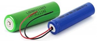
You can get a lot of perfectly working 18650 batteries out of an old laptop battery.
Where to look for firmware for your model
In most cases, new firmware is not needed to restore the controller's functionality . In most cases, flashing the controller means resetting the error. A new program for the control circuit will be needed only if the old one is lost or if erroneous changes are made that cannot be “rolled back”.
To prevent accidental loss of the controller firmware, after reading it from the battery, it is strongly recommended to save a backup copy to the computer disk.
The original, repeatedly tested and 100% functional software belongs to the manufacturer. Logically, you can download such programs on the manufacturer’s website. However, no firmware was found directly available on the websites of leading manufacturers (Acer, ASUS, HP, etc.).
You can try contacting the manufacturers' technical support. If this is not successful (this is possible - it is more profitable for the manufacturer to sell the user a new battery than to help repair the old one), you can contact service center specialists privately or search for information on specialized forums. But in these cases, the problem of illegal use of software products may arise.
Where do I use lithium batteries?
I converted my screwdriver and electric screwdriver to lithium a long time ago.
I don't use these tools regularly. Now, even after a year of non-use, they work without recharging! I put small batteries in children's toys, watches, etc., where from the element. Where exactly 3V is needed, I add one diode in series and it works just right.
I put them in LED flashlights.
Instead of the expensive and low-capacity Krona 9V, I installed 2 cans in the tester and forgot all the problems and extra costs.
In general, I put it wherever I can, instead of batteries.
How to charge a lithium-ion battery without a controller?
It’s worth saying right away that charging a Li─Ion jar bypassing the controller is highly not recommended. In this case, you will have to perform all the functions of the charging controller yourself. That is, you will need to turn off the charge in time when the upper voltage threshold is reached, and also monitor the temperature of the jar. Therefore, doing this is highly undesirable.
Charging a phone battery bank without a controller
However, there are situations when there is a real need for such charging. For example, the can is very discharged and the controller does not allow it to be charged in the normal way. This happens if the device has not been used for a long time and the battery has experienced a deep discharge.
Then you should unsolder the BMS board, connect the charger to the terminals of the can and charge. Specific charging parameters depend on the battery cell. If there are several cells, as in a laptop battery, you will need to identify the discharged ones and charge them separately. In any case, the charging process of a lithium battery must be controlled. It is necessary to check the voltage of the element and interrupt the process when the upper voltage threshold is reached. In addition, you should monitor the temperature of the jar.
Where do I buy lithium and related utilities
For sale.
At the same link you will find charging modules and other useful items for DIYers. The Chinese usually lie about the capacity and it is less than what is written.
Honest Sanyo 18650
This device has already been briefly described, I’ll try to write it in more detail and put it into practice.
Sent well wrapped in bubble wrap
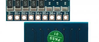
The boards have not yet been separated, but they are separated well
Board size 27x17x4mm Connection to charging via a standard microUSB connector or via duplicate contacts + and - The battery is connected to contacts B+ and B- The load is connected to contacts OUT+ and OUT-
All chips are well known and tested
Real device diagram
There is no limiting resistor at the TP4056 input - apparently the connection cable performs this function. The actual charge current is 0.93A. Charging is turned off when the battery voltage is 4.19V. The current consumption from the battery is only 3 µA, which is significantly less than the self-discharge of any battery. Description of some elements TP4056 - 1A lithium charge controller chip
Described in detail here
DW01A - lithium protection chip
FS8205A - electronic key 25mOhm 4A
R3 (1.2 kOhm) - setting the battery charging current
By changing its value, you can reduce the charging current
R5 C2 - DW01A power circuit filter. It also monitors the voltage on the battery. R6 - needed to protect against charging polarity reversal. Through it, the voltage drop across the keys is also measured for normal operation of the protection. Red LED—indication of the battery charging process Blue LED—indication of the end of the battery charge
The board can withstand battery polarity reversal only for a short time - the FS8205A switch quickly overheats. The FS8205A and DW01A themselves are not afraid of battery polarity reversal due to the presence of current-limiting resistors, but due to the connection of the TP4056, the polarity reversal current begins to flow through it.
With a battery voltage of 4.0V, the measured key impedance is 0.052 Ohm. With a battery voltage of 3.0V, the measured key impedance is 0.055 Ohm.
The current overload protection is two-stage and is triggered if: - the load current exceeds 27A for 3 μs - the load current exceeds 3A for 10 ms The information is calculated using formulas from the specification; this cannot be verified in reality. The long-term maximum output current turned out to be about 2.5A, while the key heats up noticeably, because it loses 0.32W.
The battery overdischarge protection is triggered at a voltage of 2.39V - this will not be enough, not every battery can be safely discharged to such a low voltage.
I tried to adapt this scarf into an old small, simple children's radio-controlled car along with old 18500 batteries from a laptop in the 1S2P assembly
The machine was powered by 3 AA batteries, because... 18500 batteries are much thicker than them, the battery compartment cover had to be removed, the partitions had to be bitten out, and the batteries had to be glued. In thickness they turned out to be flush with the bottom.
I glued the scarf to the roof with sealant and made a cutout for the connector.
Now the batteries can be charged like this
The red charging indicator is clearly visible through the red roof.
The blue charging end indicator is almost invisible through the roof - it is visible only from the connection connector side.
The car from below looks like it has gas cylinders :)
The car rides on these cylinders for about 25 minutes. Not too much, but oh well, enough to play with. The machine takes about an hour to charge.
Conclusion: a small and very useful device for creativity - you can take it. I will order more.
Planning to buy +227 Add to favorites Liked review +103 +259
Li-ion battery charging modules based on the TP4056 controller have been described many times on mySKU. There are many uses - from remaking toys to household crafts. The popular module TP4056 with built-in protection based on DW01A is excellent in everything, only the lower voltage protection threshold is 2.5 ± 0.1 V, i.e. 2.4V in worst case. This is suitable for most modern batteries, because... they have a threshold of 2.5 V. What if you have a bag of batteries with a lower threshold of 2.75 V? You can spit and use them with such a module. It simply increases the risk that the battery will fail after being discharged. Or you can use an additional protection board, the lower voltage threshold of which corresponds to the batteries. This is exactly the kind of board I’ll talk about today.
I understand that most people are not interested in this topic, but let it be for the sake of history, because... sometimes the question comes up.
If you use batteries with built-in protection, then you do not need this board; you can safely use a “folk” module based on TP4056 without protection. If you use batteries without protection with a minimum voltage of 2.5 V, then you can safely use a “folk” module based on TP4056 with protection.
I did not find any modules based on TP4056 with a threshold of 2.75 V on sale. I started looking for individual protection modules - there is a large selection, there are very cheap ones, but most of them are made on the same DW01A controller. The module from the review is the cheapest I could find. 275 rubles for 5 pieces.
The module is tiny, 39.5 x 4.5 x 2 mm.
The contact pads are standard for protecting one cell: B+, B- for connecting the battery and P+, P- for connecting the charger and load.
Official specifications:
The module is made on the basis of a controller. Version BM112-LFEA. Complies with technical specifications. The transistor is a double N-channel MOSFET transistor.
The connection diagram is simple:
To activate the protection module, it is enough to supply power to P+, P-. Of course, it is not necessary to connect the TP4056; a battery with a protection module can quietly live its own life (like a regular battery with protection).
How to discharge a car battery
If you think that to completely discharge the battery, it is enough to leave the headlights on overnight, then you will be right. But such actions are harmful for serviced devices, and even fatal for unserviced ones. The procedure should be carried out under strict supervision until a certain point in time, after which you should immediately begin charging.
We will describe how to properly discharge a car battery below, but for now we note that the recommended discharge current for a car battery is 5 A. Large currents are harmful, they will have an additional destructive effect on the electrode plates.
Before starting the discharge, it is necessary to measure the voltage at the battery terminals and then repeat the measurements every 2 hours. When the voltage drops to 11 V, control needs to be strengthened - measurements should be taken every 15 minutes, and when the device readings reach a level in the range of 10.5-10.9 V, the discharge should be stopped.
At the same time, you have the opportunity to assess the condition of the battery. Let's say you started discharging a fully charged battery with a capacity of 60 A*h, and at a current of 5 A it took 6 hours. In this case, multiplying the current value by the discharge time, we get 30 A*h, from which we can conclude that your battery has already half depleted its original resource.
Practice test
This is not a laboratory test, errors can be large, but it will show the overall picture.
I will use the converter as a regulated power supply, an EBD-USB tester and a TrustFire combat battery to test short-circuit protection.
Minimum voltage:
I reduce the voltage using a potentiometer. The protection is triggered at a voltage of 2.7 V. This is not the declared 2.88 V, but given the possible error, 2.75 V is suitable for batteries with a lower voltage threshold.
Maximum operating current:
The maximum operating current is 3.6 A. If exceeded, protection is triggered. The response time depends on the heating of the transistor. If it is hot, it triggers immediately when setting 3.7 A. If it is cold, then after 30 seconds. At a current of 4 A, the protection is triggered almost immediately in any case. Those. There is no declared 4 A, but 3.6 A is also good.
Module temperature:
After 5 minutes of operation at maximum current, the transistor heated up to 60 ºC, i.e. It is better not to adjoin the module close to the battery (without a gasket) during installation.
The protection resets after some time, or you can apply voltage from the memory to force a reset.
There is short circuit protection... one-time use :). I connected my combat TrustFire to the protection module and closed the P+, P- contacts via a multimeter. A current of 14 A flashed on the multimeter, and the “zilch” happened immediately. The transistor on the protection board burned out. At the same time, the protection board no longer passed current to the consumer, but essentially did not work anymore.
First of all, I built one module into the case for installing 18650 batteries (the USB connector is there just for convenience, without a converter). The kids and I usually use it for crafts using a mini drill.
How to make this device yourself
We make the board and solder everything
- Prepare or purchase the necessary tools: everything for soldering
- Carefully read the articles from the Mandatory Theory section.
- Download the necessary files for this device from github.
- Make a board for the device yourself (this is not at all difficult, everything is described in detail in our instructions).
- Purchase all the necessary components.
- Solder all components onto the board, watch our video.
- The board is ready!
No connectors are used here; the board is soldered with wires. When finished, it is better to solder the finished board in heat shrink of the required size. If necessary, you can remake the board to fit your size (for example, for an 18650 battery, which is cheaper to buy without a protection board).
Additional checks and tests
It’s very easy to check the board; just connect the consumer to the battery (for example, a device or LED) and wait until it runs out. After that, check the voltage on it, it should be about 2.9V.
Battery protection unit diagram
How it works. When the reset button is pressed, positive voltage is applied to the gate of the N-channel MOSFET power transistor.
If the voltage at the output of Zener diode U1 is higher than 2.5 volts, as determined by the voltage divider consisting of R4, R5 and R6, the cathode of U1 is connected to its anode, making it negative with respect to its emitter, R2 limits the base current to a safe value and provides sufficient current to operate U1. And transistor Q1 will keep the circuit open even when you release the reset button.
If the voltage at U1 drops below 2.5 volts, the zener diode turns off and pulls up the positive voltage at the emitter of R1, turning it off. Resistor R8 also turns off the field-effect transistor, resulting in the load being disconnected. Moreover, the load will not be turned on again until the reset button is pressed.
Most small-sized FETs are rated for only +/- 20 volts at the gate source voltage, meaning that the block circuit is suitable for no more than 12 volt devices: if higher operating voltages are required, additional circuit elements will need to be added to maintain safety fieldworker's work. An example of using such a circuit: a simple solar battery charge controller shown in the photo.
If a lower voltage than 9 volts (or higher than 15) is required, it will be necessary to recalculate the values of resistors R4 and R6 to change the adjustment range.
You can put almost any silicon PNP transistor with a rating of at least 30 volts and any N-channel MOSFET with a rated voltage of at least 30 volts and a current more than 3 times that which you are going to switch into the circuit. Throughput resistance of a fraction of Ohm. For the prototype, the F15N05 was used - 15 amperes, 50 volts. For high currents, transistors IRFZ44 (50 A Max.) and PSMN2R7-30PL (100 A Max.) are suitable. You can also connect several field-effect transistors of the same type in parallel as needed.
This device should not remain connected to the battery for a long time, since it itself consumes several milliamps due to the LED and the current consumption of U1. When turned off, its current consumption is negligible.
Is resuscitation possible?
It is potentially possible to reanimate a battery that has suffered a really deep discharge and continue its operation for the benefit of the car.
For this purpose, various methods and instruments are used.
Much depends on how severe the discharge was, how long the battery was in this state, and how many complete discharges the power source experienced before.
Manufacturers usually indicate in the technical documentation the number of deep discharges that a particular liquid lead-acid starter battery can survive.
Typically figures appear in the range of 15–20 cycles. But in reality, even 10 cycles are enough for the battery to no longer perform its functions in winter.
Therefore, the advice is extremely simple.
And there are also batteries that are not at all afraid of such situations.