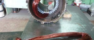
We continue the topic of electrical education about protection devices, and this post is an introduction to surge protection devices (SPDs). These are devices for your electrical panel designed to deal with short-term surges in voltage, such as those caused by a thunderstorm. The text is intended for non-techies, so welcome) Video version at the end.
Let's start with what even children know today - lightning is a discharge of electricity, sometimes it strikes man-made objects and can ruin equipment. Although this sentence sounds childish, it took humanity centuries to understand such simple and obvious things today. Knowledge about the nature and characteristics of the discharge was not given to humanity without sacrifice, let us remember Georg Wilhelm Richmann.
The first to experience regular damage from lightning strikes were telegraph workers - telegraph lines stretched across fields on poles regularly brought short-term surges of high voltage to the expensive and delicate equipment of the stations. And not only from lightning strikes on the wires themselves, but even from lightning strikes not far from the lines! And even then we had to invent ways to protect equipment from these surges. When, decades later, power engineers began to stretch their wires on poles for the newly emerging electric lighting, some of the telegraphers’ achievements came in handy.
Statistics of lightning strikes that damaged telegraphs in Belgium by month and time of day.
Clipping from the Electrical Review magazine, 1885. It is worth saying that for modern technology, lightning is no longer something extremely powerful and mind-blowing. If we take all these millions of volts and hundreds of thousands of amperes, multiply by time, we get the discharge energy, and this is only about 1 GJ of energy. If we convert it into the usual kWh, then this is only 277 kWh; you can even calculate the cost of one lightning strike. The only problem is that this amount of energy is released in a split second, which gives rise to problems that are dealt with using various technical techniques.
What happens when lightning strikes a power line? Lightning energy spreads along the conductors in search of a path to escape into the ground. This causes the voltage to increase to enormous values, due to which the insulation cannot withstand it and breaks through. In those places where the discharge occurred, damage is left by both heating and electromagnetic forces. And I would like to especially note about electromagnetic forces: due to the very high rate of current increase during a lightning strike, even a discharge in the immediate vicinity induces currents in the surrounding conductors. Therefore, even if lightning strikes a lightning rod on the roof and goes through metal structures into the ground, dangerous voltage surges may appear on the wires inside the building. Therefore, protection is built not only from direct lightning strikes, but also from various phenomena induced by lightning.
The issue of protection from atmospheric electricity and surge voltages is quite extensive, so the post is intended to give only an extremely superficial idea and does not pretend to be complete. For a more complete and in-depth study of the topic, there are links to additional materials at the end. To briefly formulate the physical meaning of protection devices, their task is to discharge into grounding all the energy induced in the lines by lightning, preventing an excessive increase in voltage. These devices were called SPDs - surge protection devices.
▍Act one. We attract lightning and send it to the ground.
Everyone has probably heard and seen about lightning rods (they are also lightning rods, and they are also lightning rods):
Lightning rod on the dome of a wooden church.
. This is not necessarily a spire sticking into the sky; for power lines it is made in the form of a lightning protection cable, which is taller than all others and does not have insulators:
A pair of lightning protection cables over power lines.
. The principle is simple - it is a conductor electrically connected to the ground, and placed as high as possible. If conditions for a lightning strike are created in this area, then most likely (but not 100% guaranteed!) the discharge will occur precisely in the grounded conductor, and not in surrounding objects. The cross-section of the conductor is selected sufficient to conduct the discharge to grounding without damage. The lightning rod acts as an “umbrella”, taking on all the elements. The analogy with an umbrella becomes even more obvious if you look at the formulas for calculating the radius of the area protected by a lightning rod - the higher the lightning rod, the larger it is. It is worth noting that there are several methods for determining the area protected by a lightning rod, and even among lightning protection specialists there is no unanimous opinion which method is more accurate. For example, a photo from the Encyclopedia Britannica shows two approaches to calculating the protected area - a cone along the height of the lightning rod and the rolling sphere method.
Areas protected by a lightning rod.
Source. The lightning rod turned out to be damn important for use in wooden houses. If previously a lightning strike on the roof could start a fire (the energy of the discharge on the way to the ground was partially converted into heat, setting everything on fire), then redirecting the discharge along a metal pin into the ground saved from such terrible consequences. And if you look closely, all modern buildings and structures have a lightning rod on the roof. And particularly important objects may generally have quite complex lightning rod designs. In those places where proper grounding is difficult to do (on a rock, sand), lightning protection becomes a completely non-trivial task. This is what lightning rods look like at a gas station in Nigeria:
The developers decided that lightning rods of this shape work better.
Source But, if the method worked flawlessly, the text would break off at this point. It was cut short before the advent of sensitive and delicate equipment.
▍Act two. Mini lightning.
Not all high-mounted conductors can be grounded to successfully redirect the discharge energy to the ground.
For example, an antenna - it must be high and cannot be grounded, otherwise it will stop receiving signals. Is it possible to make a device that would, for example, connect the antenna to the ground only at the moment of a lightning strike, and at the same time have no effect the rest of the time? You can, and this device is called a spark gap. Here is an example of a spark gap for electrical equipment from the late 19th century:
The idea of protection is simple - a minimum permissible gap is created between the protected conductor and the ground in the arrester so that during normal operation the voltage does not exceed the breakdown voltage of the gap. If for some reason the voltage in the protected line increases (due to a lightning strike or due to surges from the operation of electrical equipment), then an electrical breakdown occurs in the gap - an electric arc is ignited, which, due to the ionization of the gas, conducts current well. It is this arc that provides a temporary electrical connection to the ground, and goes out if the voltage drops below the arc quenching voltage.
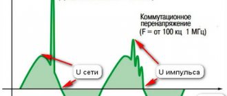
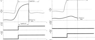
But there are two problems. The first is the hardly predictable breakdown voltage of the spark gap - a change in temperature, air humidity - and the voltage changes. A little corrosion - the voltage has changed. The crooked adjuster handles have changed a lot. The second drawback is more fundamental - the voltage at which breakdown occurs and the voltage at which the arc goes out are different. Moreover, the arc ignition voltage also depends on the rate of voltage rise. The graph in the picture just shows the “hump” - until the spark gap is triggered, the voltage has time to increase, then the arc lights and the voltage drops. The dotted line shows the voltage graph when protected by a varistor.
The picture is taken from here.
If the first drawback was overcome by enclosing the spark gap in a sealed flask filled with a pre-prepared mixture of gases, then nothing could be done about the second. Yes, with various tricks you can reduce the difference between the breakdown voltage and the voltage when the arc goes out, but not radically. Moreover, the quenching voltage must be HIGHER than the voltage of the power source (*with reservations). Otherwise, an unpleasant situation may arise when a lightning strike breaks through the arrester and goes into the ground, but the generator powering the line will not allow the arc to go out. And the arc in the spark gap will burn until one of them breaks. Here is an example of an RB-5 arrester, domestically produced from communication equipment - the flask is sealed and filled with an inert gas:
In principle, before the widespread use of semiconductor devices (somewhere before the mid-60s), protection in the form of arresters suited everyone. With a proper insulation safety margin, most equipment could withstand a short-term voltage surge of a couple of kV (until the arrester operates). But then semiconductor devices came into widespread use, for which even a small short-term increase in voltage meant death.
Dischargers are still used today and very widely. Moreover, arresters are produced in a huge range for all occasions, from small ones for protecting communication lines to huge ones for protecting power lines. Here's an example of what the arresters look like in a mini-PBX board (cylindrical with the manufacturer's brand EPCOS), to protect against high voltage pulses that may end up in the telephone line:
General settings of three-phase relay
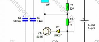
In order for the 3-phase voltage control relay to work, you need to make some settings. After connecting the device to the electrical circuit, power is supplied to it, and the following information appears on the display:
- If the image on the display blinks, this indicates a lack of voltage.
- The appearance of dashes indicates a violation of the phase sequence or the absence of one.
- If the display flashes for a long time, you should suspect that the contactor is not connected.
You can set up a three-phase voltage control relay using two built-in buttons; they have triangles on them. They are located on the right side of the device: the top button with a triangle up, and the bottom button down. To get the maximum shutdown limit, you need to press the top button. She lingers for a few seconds. After this, a number appears in the central screen displaying the factory level. The button must be pressed until the desired value appears. After settings, the device will be automatically programmed within ten minutes.
How to set the restart time
On the right side of the display there is a control button with a drawn clock. It must be pressed and held until the factory value appears. The time interval is 15 seconds. This means that after the voltage normalizes, the device will turn on the electricity again after this period of time.
Indicators can be reduced. A few clicks on the top or bottom button are enough for the necessary parameters to appear.
How to adjust phase imbalance
To configure, you must simultaneously press both triangular buttons. After this, you can see 50V on the display. This means that power will not be supplied to the network when the phase imbalance reaches this value. To decrease or increase a parameter, you need to set the time of one of the buttons.
▍Act three. Semiconductors protect semiconductors.
Varistors have come to replace arresters in protecting lines (and not only power lines, but also, for example, communication lines, but the post is mainly devoted to power lines with a voltage of 220-230V). These are a special type of resistor whose resistance depends on the applied voltage. This is what their current-voltage characteristic looks like, which shows the relationship between the current through the device and the applied voltage:
Source
That is, they behave approximately
like arresters. If the voltage is below the threshold, then their resistance is high, there is only a tiny leakage current. If the voltage exceeds the threshold, then the varistor changes its resistance quite significantly, beginning to conduct current well. But, unlike a spark gap, it returns to its original state with high resistance as soon as the voltage drops below the threshold. As a result, the voltage at the varistor contacts turns out to be relatively stable; it will compensate for the increase in voltage by increasing the current through itself, which will prevent the voltage from rising.
Purely technically, a varistor is a sintered ceramic tablet made of a substance that has the properties of a semiconductor, for example, zinc oxide granules in a matrix of a mixture of metal oxides, which is why it is called MOV - Metal Oxide Varistor. The granules create a huge number of pn junctions that conduct current in one direction. But since there are many of them and in a random order, they are useless for rectifying current. But the property of causing an electrical breakdown when a certain voltage is exceeded (and the electrical breakdown of the pn junction is reversible) turned out to be very useful. By adjusting the thickness of the tablet, it is possible to achieve a fairly stable threshold voltage during production. And by increasing the volume of the washer, you can increase the maximum pulse energy that the varistor can absorb.
The varistor turned out to be not ideal, so it did not replace, but only supplemented the arresters. For the huge advantage - the absence of a difference between the breakdown voltage and the recovery voltage, varistors are forgiven for leakage currents, limited service life (after a certain number of operations they can lose characteristics), large size with modest permissible discharge energies. A varistor connected to the line will dampen voltage surges approximately as follows:
Since a varistor can become unusable over time, and for example, begin to conduct current when it is not required, causing a short circuit, it is necessary to provide protection against short circuits. Large, powerful varistors on a DIN rail, for protecting power lines, often contain built-in protection. For example, this is what the filling of a varistor in a panel from IEK looks like:
You can see the varistor tablet itself (blue). Electrodes are attached to it and a spring-loaded flag rests on an electrode soldered with low-melting solder... If the varistor heats up beyond a reasonable level (no matter from an incoming pulse from lightning, or due to degradation), then the solder melts, the electrode is disconnected, breaking the circuit, and the spring lowers the flag, indicates a varistor fault. If protection is not provided, uncontrolled heating of the varistor can be caused by a fireman.
Small varistors can be found in many electronic devices to protect against high voltage surges that accidentally come through the network. In most extension cords that call themselves “surge protectors,” all filtering comes down to the presence of a pair of varistors inside. Here in the photo you can see varistors (blue) in different extension cords:
Features of the device and scope of application
Protection of a three-phase electric motor from overload is necessary both in everyday life and in many industrial areas.
A three-phase voltage relay is used to ensure proper operation:
- In equipment with an ATS circuit and any other equipment that uses an electric motor load.
Three-phase voltage relays from Novatek Electro are available in various modifications, taking into account the needs of problematic networks, where you can observe not only voltage interruptions, but also switching and pulse noise. The devices are equipped with a special delay during voltage sags, which makes the three-phase digital voltage relay effective in operation during short-term voltage sags.
Three-phase voltage relay devices are mounted on a standard DIN rail, they are lightweight and small-sized, which makes the process of installation and further maintenance of the device simple and safe.
The device is connected in parallel to the load, but what is noteworthy is that its operation does not depend on the load power. The three-phase protection relay at the outputs has two groups of contacts (closed and open), independent of each other and capable of switching loads up to 5A.
▍Act four. Protection for the most delicate.
I included this section for the sake of completeness. In addition to varistors and arresters, there are also protection devices - semiconductor suppressors (TVS-transient voltage suppressor), also known as TVS-diodes, also known as semiconductor voltage limiters. These are specially designed diodes that operate on the reverse branch of the current-voltage characteristic (yes, the same one where reversible electrical breakdown occurs in varistors). Physically, they perform the same function as other protection devices - they do not conduct current if the voltage is normal and begin to conduct current if the voltage for some reason exceeds the permissible value, thereby acting as a limiter. The photo shows a fairly large specimen, they can be quite miniature: Photo from the catalog of my favorite Promelelectronics.
TVS diodes come in both lead-out and surface-mount packages. There are assemblies with several TVS diodes to protect groups of lines. Semiconductor voltage limiters are almost perfect in all respects, except for one thing - the amount of pulse energy that they are able to limit by absorbing excess is very small. Creating protection based on them that can at least somehow compare the characteristics with arresters or varistors will be too expensive. Therefore, they have found application where compact protection of the most delicate and sensitive electronics from small power surges, for example from static electricity, is needed. Rest assured - in your phone, all contacts that lead inside (USB, headphones) are protected by small TVS diodes that will not allow the voltage on these contacts to rise above 5 V, even if you accidentally “click” them with electricity while taking off your sweater.
If you want to learn more about semiconductor voltage limiters, you can do so here and here. But, if you are not an electronics developer, then it is unlikely that you will somehow interact with these protection devices.
Entry 3
Below are photos of the assembly and installation of the shield on the third input.
3 – assembly process.
Pay attention to the color sequence of the wires. Question: Which country am I a patriot?
I decided to use a flexible PVS 4x4 cable, because I had suffered in the first previous cases with solid cores. But in this case it is necessary to use tips, because... for screw terminals, which are used in Barriers, the strand is not comme il faut.
3 – Electrical panel assembled and installed
In the previous two versions, the wires went from top to bottom under the DIN rail, which is a little annoying.
Therefore, here I expanded the consciousness and the distance between the phases, and laid wires into the resulting gaps. The fact is that the Barrier block occupies approximately 2.8 modules on the DIN rail, and there will be gaps in any way. So why not use them for convenient installation?
3 – Shield with Barriers installed
3 – General view
3 – Complete
▍Act five. Zone defense concept.
Is it possible to install a universal surge protection device in the electrical panel at the entrance to the house and not have any problems?
Unfortunately no. If only because even if you suppressed all unwanted surges at the entrance to the house, you can re-catch them with the wiring inside the building, for example, when the lightning discharge current follows from the lightning rod into the ground somewhere behind the wall - the electromagnetic field is so powerful that in any conductor will induce a current pulse. Or, for example, that the impulse will re-enter the network through the telephone, arriving along the telephone line. Therefore, the process of building protection becomes more complicated - it is necessary to analyze all the ways of penetration of an electromagnetic pulse from lightning into the protected object. In order not to install on each device a complete set of devices for protection against direct lightning strikes (it would be too expensive), they came up with the concept of zonal protection and corresponding classes of devices. An object, the electrical content of which is protected from lightning damage, is divided into zones according to the degree of lightning exposure. All lines (power, communications) passing from zone to zone are equipped with protection devices at the zone boundaries. It's easier to understand this with an abstract example of a house:
Picture taken from OBO Betterman manual.
Lightning protection guide (LPZ - lightning protection zone - lightning protection zone) Zone 0a is the zone where lightning can directly strike. The conductor may contain the full lightning current. Zone 0b is a zone where lightning will not directly strike, but the conductor may contain a partial lightning current, either due to the electromagnetic field or simply due to an insulation breakdown. Zone 1 - This is the zone where lightning-induced current can occur. Zone 2,3,4, etc. - a zone where the lightning-induced current is weakened and less than in the higher zone. There can be as many zones as you like, like in a nesting doll.
That is, it is clear - when moving from zone to zone, the electromagnetic pulse of lightning weakens, including due to protection devices at the borders
zones, and due to shielding and attenuation in space. For example, a concrete wall with grounded reinforcement inside can serve as such a screen. Zones are usually divided by natural obstacles - a wall, cabinet body, device body, etc.
And for convenience, protection devices are divided into classes. And when the division into zones is clear, it is enough to take a device of the corresponding class from the catalog. Class I (B) are devices capable of withstanding partial lightning current (zone 0), and are intended for installation on the input panel. (where zone 0 goes into zone 1) Class II (C) - these are devices that can withstand less current than a Class I device, but they are cheaper and the voltage to which they cut the pulse is less. Designed for installation on a distribution board. (Just where zone 1 turns into zone 2) Class III- (D) These are devices that can withstand an even smaller impulse than class II, but cut off the impulse almost completely. And they are designed for installation on the end user’s switchboard. Many well-designed devices have similar protection already inside them.
Why not put Class I protection devices everywhere? But simply because installing a class I device where class III is more than enough, for example, for the end consumer, is an unjustified budget overrun. It's like building a fully equipped fire station where you only need to install a fire extinguisher. In addition, the more brutal and powerful the protection device, the greater the magnitude of the pulse voltage that leaks through it to the consumer. (the higher the limiting voltage, see the picture above)
Picture from the Schneider electrician manual
But if you want everything at once, there are combined devices, for example Class I+II, which correspond to the parameters of several classes at once, but for such versatility the manufacturer will ask for additional money.
Connection diagram and installation of voltage relay
Relay elements
The device will perform its functions regardless of the position. But each model has its own connection diagram. You can see it on the body.
For all devices, there are the same rules that are designed to control the process of connecting the relay to the electrical circuit.
The input contacts are connected to the network through a contactor or starter. The conductors of all phases are combined with the terminals, which are located on the top of the device. Elements are marked like this:
- Phases with letters A, B and C.
- N – neutral wire terminal.
- 1,2,3 – lower terminals.
First, from terminal 1, the conductor is connected to the output of the coil, which is located in the contactor. Terminal 3 is connected to any phase. The second output is connected to the neutral conductor of a three-phase network.
The power elements are connected as follows:
- Each phase that supplies current is connected to the input terminal of the contactor.
- The conductors are connected to the output terminals.
- To connect neutral conductors, a common neutral bus is installed in the distribution panel.
To ensure reliable contact, special tips are used.
▍Act six. Standard zipper.
Each lightning strike is unique in its characteristics. But protection devices need to be somehow tested, compared, developed, so we had to agree on some characteristics of the electromagnetic pulse that lightning induces. Therefore, on the front panel of the protection devices, as well as in the documentation, you can see: (look at the markings on the sawn SPD from IEK in the photo above)
- The peak value of current that passes through a device without damaging it, in thousands of amperes (kA). For example, 50 kA means that the peak current in the pulse reaches 50,000 Amperes.
- Record the duration of the pulse, in microseconds. It is indicated through a fraction. For example, 10/350 means that the pulse rises to the maximum current value in 10 microseconds, and then smoothly decreases to zero in 350 microseconds. Or for example 8/20. (10/350 is a long and powerful pulse, characteristic of a direct hit by a discharge, and 8/20 is a short one, more characteristic of a lightning strike nearby)
- Operating voltage. This is the normal voltage in the line to which the protection is connected.
- Clipping voltage, in volts. This is the value of the residual pulse voltage at the terminals of the device (later I will indicate why this is important), to which the protection device can reduce it.
- Device class (see the part about the zone concept).
It is worth noting that even many years of collected statistics do not exclude the possibility that you have not sinned so much that you will be struck by abnormally powerful lightning, but the probability of this is very low. (For example, IEC 62305-1 believes that even for the most notorious sinners, lightning with a charge of more than 300 C is released in less than 1% of cases.)
Here is a beautiful illustration from the OBO BETTERMANN manual, which illustrates the statistics of lightning current discharges and how different lightning protection levels (LPL) cover them:
Since the process of predicting the current of lightning that will strike an object in the future is akin to the process of predicting the price of Bitcoin (that is, fortune telling), they came up with different levels of lightning protection, and the picture above clearly shows how they relate. The required level of protection is selected according to an assessment of the risk of damage from lightning strikes.
Principle of operation
The principle of operation of surge arresters is explained by the nonlinear nature of the current-voltage characteristics (VC) of varistors. For their manufacture, a material is used where zinc oxide is used in a mixture with oxides of other metals. Due to the composition of this mixture, a column assembled from varistors is a combination of parallel and series connections of pn junctions, which determines the nature of the current-voltage characteristics of nonlinear limiter resistors.
When the voltage characteristics in the network correspond to the nominal values, the limiter is in a non-conducting state. The current in varistors is negligible and is explained by their capacitive nature. When a voltage pulse appears in the network, the magnitude of which can cause a breakdown of the insulation of electrical equipment, a significant current pulse will occur in the circuit of nonlinear resistors of the arrester, in accordance with their current-voltage characteristics. Ultimately, this reduces the magnitude of the overvoltage to parameters that are safe for trouble-free operation of the equipment. When the network voltage returns to normal, the surge arrester returns to non-conducting mode.
▍Act seven. We spoil everything by forgetting about the little things.
The above is relevant for a spherical horse in a vacuum.
In real life there are a huge number of subtleties that are omitted for the sake of simplicity, but sooner or later they will make themselves felt. Here are examples of some of them: 1. Self-inductance and resistance of conductors.
A 1 meter long piece of wire has an inductance of approximately 1 μH and non-zero resistance. This means that at high rates of current growth (and they are typical for lightning), an extra supply of wire can reduce the meaning of protection to zero. Many manufacturers clearly indicate in their manuals that the length of the conductors from the line to the terminals of the protection device should be as short as possible, and in total not exceed 0.5 m. Here is a visual picture from the OBO BETTERMANN manual of how an extra 2 meters of wire affected the protection. If the SPD (orange) cuts the incoming pulse to a value of 1.5 kV, then an additional 2 kV drops on the conductors, and as a result, a pulse with a voltage of 3.5 kV will arrive at the load.
A very elegant way to reduce the influence of conductors is to connect like this:
Some manufacturers, for ease of installation, generally provide double terminals, for example, as on this device (domestic, by the way):
2. Resistance plays a role.
With a lightning discharge current of 50 kA, a voltage difference of 5 kV will be created on a conductor with a resistance of 0.1 Ohm when the current flows. Therefore, the SPD should be connected with the thickest possible conductor, at least 6 mm2, even if the line itself is 2.5 or even 1.5 mm2. If you connected the SPD in a V-shape as in the photo above, then only the grounding conductor will remain thick.
3. It is useless to connect protection devices in parallel without coordination.
The thought may creep in that if we install several protection devices in parallel, we will get Megaprotection. But it doesn't work that way. When an impulse arrives along the line, one person will act first and take the entire blow. In order for the cascade of protections to work consistently, and, as necessary, more and more powerful devices are connected to pulse absorption, they must be coordinated with special chokes. But since calculating such a cascade is not an easy task, it is extremely difficult to find matching devices in the catalogs of SPD manufacturers. The manufacturer began to produce combined devices, coordinating them internally. That is, instead of installing a II and III class SPD next to each other, you need to take a ready-made class II+III device.
4. We install an automatic machine instead of a fuse.
If you carefully read the documentation for surge protection devices, many manufacturers require the installation of fuses to protect against short circuits - if the device fails, it can short circuit the protected line to ground. And in this scenario, it is better if the fuse blows and disconnects the protection device from the line than if the input circuit breaker does this and de-energizes the load. But see point 1 - it is stupid to first achieve the minimum inductance of the conductors, and then plug in a circuit breaker, inside of which there is an electromagnetic release in the form of an inductance coil. As a result, the circuit breaker will work as an additional virtual few meters of wire (see point 1) increasing the voltage of the pulse reaching the load. And that is why it is highly advisable to use fuses. (this is without taking into account that there is a danger that a current pulse of 10-50-100 kA will cause sintering of the contacts in the machine)
5. SPDs based on varistors have leakage current.
It is small, but not zero. And here common sense takes a backseat to the power grid company, which has its own opinion on where the SPD should be installed. So it may turn out that you install the SPD after the meter. But since the meter is the property of the electric grid company, you can put on a cool face when the meter burns out after a thunderstorm and they come to replace it.
6. Lack of control.
Imagine that you have equipped an electrical panel with surge protectors that powers a weather station in a deserted place. A thunderstorm passed nearby, the SPDs fulfilled their function, saved the station’s contents from damage, but died themselves - they were turned off by the protection. And we get a situation where the station works normally, but at the same time has no protection, and the next thunderstorm can put it out of action. It is precisely from such unpleasant situations that there are SPDs with contacts that open/close when the protection fails (for example, in the photo of SPD-220 these are contacts 4 and 5). In this case, the deceased SPD can send a signal to the dispatch system that it is time to send an installer to replace the protection.
RCD connection diagram
In apartments, connecting a three-phase network is rare. This option is popular for private homes. The protection device is connected in several ways:
- A 380 V 2-pole voltage relay is not suitable for home use. Use 4-pole analogues. 1 neutral conductor and 3 phase conductors are connected to them. The circuit is complicated by the fact that each line is equipped with its own RCD device. It is important to choose the right wires. For a single-phase network, the standard VVG version is suitable, but for a 3-phase network you need a fire-resistant VVGng.
- General RCD for 3-phase network + meter. The circuit contains an electricity meter. Group RCDs are located in the system for servicing individual lines. This scheme requires the installation of a large electrical panel with many wires and electrical appliances.
If an apartment or house has a large number of lighting and socket circuits, as well as a variety of household appliances, it is advisable to install double protection with a common RCD.
▍Act eight. Practical.
Anyone who has read this far has probably already asked the question - why do I need an SPD and how to turn it on?
Let's get down to specifics. If you live in a private house and electricity is supplied to the house via an overhead power line, then you need an SPD, and class I. (In some cases, class II may be enough, but there are a lot of “buts”) If you live in an apartment building , all engineering systems of which are in order, then the SPD is not an essential device, but it will not make it worse. A typical scheme for using SPDs looks like this (again, I took the picture from the OBO BETTERMANN manual:
Input on the left. Class I surge protectors are located immediately after the input circuit breaker (or after the electric meter, if the electric grid company wishes), one for each phase. Re-grounding (5) is visible and TN-C becomes TN-CS. Without grounding, the SPD does not work - where should it discharge the pulse energy, except into the ground?
Inside the building, on an intermediate switchboard, for example a floor switchboard, class II SPDs are used, which will suppress what could pass through the SPDs at the input. Please note that between N and PE there is an SPD specially designed for this purpose, since normally the voltage between N and PE is low.
And finally, a class III surge protector is installed next to the consumer. Well-designed devices already have surge protection built into them by the manufacturer.
▍Summary:
- Electronic equipment in your home is vulnerable to electromagnetic pulses from lightning strikes, even nearby.
- To protect against these pulses (as well as from pulses arising when switching inductive loads), SPDs were invented - surge protection devices. An SPD can contain both a surge arrester and a varistor, it all depends on the characteristics that the SPD must provide.
- SPDs are produced in different classes, from I to III. Class I devices are suitable for installation on the input panel of a house. But there are also devices that can provide protection corresponding to several classes.
- The entire protective effect of the SPD can be negated by incorrect connection.
- The SPD may fail, and without regular inspection it will go unnoticed.
Video version of the post, not word for word, but close to the text, for those who like to listen and watch:
▍What else to read to deepen your knowledge:
1. First of all, regulatory documentation.
We say Okay, Google, “Lightning protection device for buildings, structures and industrial communications: Collection of documents. Series 17. Issue 27" and carefully study, the collection contains regulatory documents: Instructions for the installation of lightning protection of buildings and structures (RD 34.21.122-87) and Instructions for the installation of lightning protection of buildings, structures and industrial communications (SO 153-34.21.122- 2003) and also separately google and look at GOST R IEC 62305. It consists of a large number of parts, but not a single blogger on the Internet can exceed the regulatory requirements. 2. There is a wonderful website https://zandz.com The guys not only recorded webinars with invited specialists in the field, but also made transcripts of them, so you can quickly read them instead of watching videos. They have posted all this splendor for free, but registration is required. Respect. Video recordings of webinars are on their YouTube channel and are available without registration, for example webinars by Prof. Bazelyan (https://www.youtube.com/watch?v=R-KbjRb4Yuw&list=PLjJ4-onvu94qpAA_zsCLkrTzJMBLXU0ns) 3. A good article on Habrahabr 4. Many manufacturers produce design manuals - such veiled advertising, where the basics are explained in simple language and at the same time excerpts from the catalog of equipment that solves the problem are given. There is an excellent manual in Russian from Schneider Electric (https://www.se.com/ru/ru/download/document/MKP-CAT-ELGUIDE-19/), we are interested in section J, dedicated to surge protection. Everything in it is quite simple, clear and accurate. 5. If you speak English, then companies that produce everything for lightning protection have released wonderful manuals. Of course, with a bias in my products, but as you can see, I borrowed some illustrations from them. This is OBO BETTRMAN lightning protection guide, Dehn lightning protection guide. I would also like to express my gratitude to Pavel, Denis, Evgeniy and Victor for reviewing the draft article. Other articles in the series: About fuses, about circuit breakers, about RCDs, about choosing a circuit breaker, about protection devices.
Specifications
- Maximum effective voltage. By this concept it is necessary to understand the value of the highest voltage value at which the limiter is able to maintain its functionality without a time limit.
- The rated voltage is equivalent to the value that the arrester can withstand for 10 minutes.
- Conduction current. The magnitude of the current in the circuit of nonlinear resistors during the period of exposure to the rated values of the applied voltage. As a rule, it is of negligible importance.
- Rated discharge current. A parameter that determines the classification of the limiter in lightning conditions.
- Estimated current of switching overvoltage. The current value that determines the classification for switching overvoltages.
- Current carrying capacity. A value equivalent to the line discharge class.
- Short circuit resistance. Category of the ability of an arrester to withstand short-circuit currents while maintaining the integrity of the protective shell.
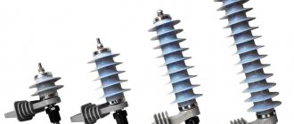
Protection of the electrical equipment of administrative buildings, apartment buildings and enterprises is entrusted to the relevant services of energy companies; protecting your home from the undesirable consequences of a lightning discharge is entrusted to the homeowner. Currently, this issue is resolved simply. Specialized stores offer a wide selection of surge suppressors of varying degrees of complexity and price range.
The figure below shows the connection of an arrester to a single-phase network and the symbol on the diagram. Connecting a surge suppressor to your home electrical network is not difficult, but it is better to entrust this operation to a specialist if you do not have experience in electrical installation work.
Finally, we recommend watching a video that clearly examines the design and operating principle of nonlinear surge suppressors:
https://youtube.com/watch?v=2ZZwQRD6q4I
So we looked at the device, purpose and principle of operation of the surge suppressor. As you can see, there are different types and designs of these devices, so you can choose the appropriate option for your own application conditions.
It will be interesting to read:
- Testing of nonlinear surge suppressors
- Why do you need a voltage relay?
- How to protect yourself from electrical interference
https://youtube.com/watch?v=2ZZwQRD6q4I