A battery charge indicator is a necessary thing in the household of any motorist. The relevance of such a device increases many times over when, for some reason, a car refuses to start on a cold winter morning. In this situation, it’s worth deciding whether to call a friend to come and help you start from your battery, or whether the battery has died for a long time, having discharged below a critical level.
Why monitor your battery's condition?
A car battery consists of six batteries connected in series with a supply voltage of 2.1 - 2.16V. Normally, the battery should produce 13 - 13.5V. Significant discharge of the battery should not be allowed, since this reduces the density and, accordingly, increases the freezing temperature of the electrolyte.
The higher the battery wear, the less time it holds a charge. In the warm season, this is not critical, but in winter, side lights forgotten while turned on can completely “kill” the battery by the time it is returned, turning the contents into a piece of ice.
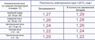
In the table you can see the freezing temperature of the electrolyte, depending on the degree of charge of the unit.
| Dependence of the freezing temperature of the electrolyte on the state of charge of the battery | ||||
| Electrolyte density, mg/cm. cube | Voltage, V (no load) | Voltage, V (with load 100 A) | Battery charge level, % | Electrolyte freezing temperature, gr. Celsius |
| 1110 | 11,7 | 8,4 | 0,0 | -7 |
| 1130 | 11,8 | 8,7 | 10,0 | -9 |
| 1140 | 11,9 | 8,8 | 20,0 | -11 |
| 1150 | 11,9 | 9,0 | 25,0 | -13 |
| 1160 | 12,0 | 9,1 | 30,0 | -14 |
| 1180 | 12,1 | 9,5 | 45,0 | -18 |
| 1190 | 12,2 | 9,6 | 50,0 | -24 |
| 1210 | 12,3 | 9,9 | 60,0 | -32 |
| 1220 | 12,4 | 10,1 | 70,0 | -37 |
| 1230 | 12,4 | 10,2 | 75,0 | -42 |
| 1240 | 12,5 | 10,3 | 80,0 | -46 |
| 1270 | 12,7 | 10,8 | 100,0 | -60 |
A drop in charge level below 70% is considered critical. All automotive electrical appliances consume current, not voltage. Without load, even a severely discharged battery can show normal voltage. But at a low level, during engine startup, a strong voltage drop will be noted, which is an alarming signal.
It is possible to notice an approaching disaster in a timely manner only if an indicator is installed directly in the cabin. If, while the car is running, it constantly signals about discharge, it’s time to go to the service station.
Circuit diagram of a simple charger for a car battery
The formula for a normal charge is as simple as 5 kopecks - the basic battery capacity divided by 10. The charging voltage should be a little over 14 volts (we are talking about a standard 12 volt starter battery).
A simple circuit diagram of a car charger consists of three components: power supply, regulator, indicator.
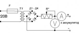
Classic - resistor charger
The power supply is made of two winding “trans” and a diode assembly.
The output voltage is selected by the secondary winding. The rectifier is a diode bridge; a stabilizer is not used in this circuit. The charging current is controlled by a rheostat. Important! No variable resistors, even those with a ceramic core, will withstand such a load.
A wire rheostat is necessary to counteract the main problem with such a circuit - excess power is released in the form of heat. And this happens very intensively.
Of course, the efficiency of such a device tends to zero, and the service life of its components is very low (especially the rheostat). Nevertheless, the scheme exists, and it is quite workable. For emergency charging, if you don’t have ready-made equipment at hand, you can literally assemble it “on your knees.” There are also limitations - a current of more than 5 amperes is the limit for such a circuit. Therefore, you can charge a battery with a capacity of no more than 45 Ah.
DIY charger, details, diagrams - video
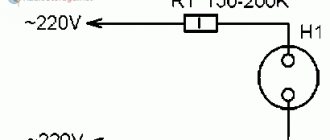
Quenching capacitor
The operating principle is shown in the diagram.
Thanks to the reactance of the capacitor included in the primary winding circuit, the charging current can be adjusted. The implementation consists of the same three components - power supply, regulator, indicator (if necessary). The circuit can be configured to charge one type of battery, and then the indicator will not be needed.
The highlight of the charger is the capacitor battery. The peculiarity of circuits with a quenching capacitor is that by adding or decreasing capacitance (simply connecting or removing additional elements) you can regulate the output current. By selecting 4 capacitors for currents of 1A, 2A, 4A and 8A, and switching them with ordinary switches in various combinations, you can adjust the charge current from 1 to 15 A in 1 A steps.
At the same time, there is no parasitic heating (except for the natural one generated by the bridge diodes), the efficiency of the charger is high.
What indicators exist
Many batteries, especially maintenance-free ones, have a built-in sensor (hygrometer), the operating principle of which is based on measuring the density of the electrolyte.
This sensor monitors the condition of the electrolyte and the relative value of its indicators. It is not very convenient to climb under the hood of a car several times to check the condition of the electrolyte in different operating modes.
Electronic devices are much more convenient for monitoring the condition of the battery.
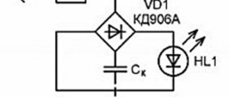
Charging from USB port
You can make a charger for nickel-cadmium batteries based on a regular USB port. At the same time, they will be charged with a current of approximately 100 mA. The scheme, in this case, will be as follows:
At the moment, there are quite a lot of different chargers sold in stores, but their cost can be quite high. Considering that the main point of various homemade products is precisely to save money, self-assembly is even more advisable in this case.
This circuit can be modified by adding an additional circuit to charge a pair of AA batteries. Here's what we ended up with:
To make it more clear, here are the components that were used during the assembly process:
It is clear that we cannot do without basic tools, so before starting assembly you need to make sure that you have everything you need:
- soldering iron;
- solder;
- flux;
- tester;
- tweezers;
- various screwdrivers and knife.
Interesting material about making it yourself, we recommend viewing it
A tester is necessary to check the performance of our radio components. To do this, you need to compare their resistance, and then check it with the nominal value.
For assembly we will also need a case and a battery compartment. The latter can be taken from the children's Tetris simulator, and the body can be made from a regular plastic case (6.5cm/4.5cm/2cm).
We attach the battery compartment to the case using screws. The board from the Dandy console, which needs to be cut out, is perfect as a basis for the circuit. We remove all unnecessary components, leaving only the power socket. The next step is to solder all the parts based on our diagram.
The power cord for the device can be taken from a regular computer mouse cord with a USB input, as well as part of the power cord with a plug. When soldering, polarity must be strictly observed, i.e. solder plus to plus, etc. We connect the cord to USB, checking the voltage supplied to the plug. The tester should show 5V.
Finally, you need to set the charging current. To do this, you need to break the circuit connecting VD1 and the positive polarity of the battery. We connect the tester in such a way that its plus is connected to the diode, and its minus is connected to the battery. We set the current measurement mode (200 mA).
We turn it on, after which the LED should light up, of course, if everything is done correctly. Then we set the required charging current (100 mA) by changing the resistance on resistor R1. We carry out this procedure for the second AA battery.
Another interesting video on this topic
Types of battery charge indicators
Automotive stores sell many of these devices, differing in design and functionality. Factory devices are conventionally divided into several types.
By connection method:
- to the cigarette lighter socket;
- to the on-board network.
By signal display method:
- analog;
- digital.
The principle of operation is the same, determining the battery charge level and displaying information in a visual form.
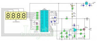
Schematic diagram of the indicator
Circuit diagram of a capacitor charger without automatic shutdown
For those who do not have sufficient experience in assembling electronic circuits or do not need to automatically turn off the charger after charging the battery, I offer a simplified version of the circuit diagram for charging acid-acid car batteries. A distinctive feature of the circuit is its ease of repetition, reliability, high efficiency and stable charging current, protection against incorrect battery connection, and automatic continuation of charging in the event of a loss of supply voltage.
The principle of stabilizing the charging current remains unchanged and is ensured by connecting a block of capacitors C1-C6 in series with the network transformer. To protect against overvoltage on the input winding and capacitors, one of the pairs of normally open contacts of relay P1 is used.
When the battery is not connected, the contacts of relays P1 K1.1 and K1.2 are open and even if the charger is connected to the power supply, no current flows to the circuit. The same thing happens if you connect the battery incorrectly according to polarity. When the battery is connected correctly, the current from it flows through the VD8 diode to the winding of relay P1, the relay is activated and its contacts K1.1 and K1.2 are closed. Through closed contacts K1.1, the mains voltage is supplied to the charger, and through K1.2 the charging current is supplied to the battery.
At first glance, it seems that relay contacts K1.2 are not needed, but if they are not there, then if the battery is connected incorrectly, current will flow from the positive terminal of the battery through the negative terminal of the charger, then through the diode bridge and then directly to the negative terminal of the battery and diodes the charger bridge will fail.
The proposed simple circuit for charging batteries can be easily adapted to charge batteries at a voltage of 6 V or 24 V. It is enough to replace relay P1 with the appropriate voltage. To charge 24-volt batteries, it is necessary to provide an output voltage from the secondary winding of transformer T1 of at least 36 V.
If desired, the circuit of a simple charger can be supplemented with a device for indicating charging current and voltage, turning it on as in the circuit of an automatic charger.
How to make a battery charge indicator using LEDs?
There are dozens of different control schemes, but they produce identical results. It is possible to assemble such a device yourself from scrap materials. The choice of circuit and components depends solely on your capabilities, imagination and the assortment of the nearest radio store.
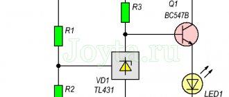
Here is a diagram to understand how the LED battery charge indicator works. This portable model can be assembled “on your knee” in a few minutes.
D809 - a 9V zener diode limits the voltage on the LEDs, and the differentiator itself is assembled on three resistors. This LED indicator is triggered by current in the circuit. At a voltage of 14V and above, the current is sufficient to light up all the LEDs, at a voltage of 12-13.5V VD2 and VD3 up, below 12V - VD1 .
A more advanced option with a minimum of parts can be assembled using a budget voltage indicator - the AN6884 (KA2284) chip .
Circuit of LED battery charge level indicator on voltage comparator
The circuit operates on the principle of a comparator. VD1 is a 7.6V zener diode, it serves as a reference voltage source. R1 – voltage divider. During the initial setup, it is set to such a position that all LEDs light up at a voltage of 14V. The voltage supplied to inputs 8 and 9 is compared through a comparator, and the result is decoded into 5 levels, lighting the corresponding LEDs.
Printed circuit board and assembly parts
The printed circuit board is made of single-sided foil PCB measuring 40 by 37 mm, which can be downloaded here. It is designed for mounting DIP elements of the following type:
- MLT-0.125 W resistors with an accuracy of at least 5% (E24 series) R1, R2, R3, R4, R7, R9, R10, R11 – 1 kOhm, R5, R8 – 5.1 kOhm, R6, R12 – 10 kOhm;
- any low-power diode VD1 with a reverse voltage of at least 30 V, for example, 1N4148;
- Zener diode VD2 is low-power with a stabilization voltage of 6.2 V. For example, KS162A, BZX55C6V2;
- LEDs LED1-LED5 – indicator type AL307 of any color.
This circuit can be used not only to monitor the voltage on 12 volt batteries. By recalculating the values of the resistors located in the input circuits, we get an LED indicator for any desired voltage. To do this, you should set the threshold voltages at which the LEDs will turn on, and then use the formulas for recalculating the resistances given above.
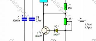
Battery charging controller
To monitor the condition of the battery while the charger is operating, we make a battery charge controller. The device circuit and components used are as accessible as possible, while at the same time providing complete control over the battery recharging process.
The operating principle of the controller is as follows: as long as the voltage on the battery is below the charging voltage, the green LED lights up. As soon as the voltage is equal, the transistor opens, lighting up the red LED. Changing the resistor in front of the base of the transistor changes the voltage level required to turn on the transistor.
This is a universal monitoring circuit that can be used for both high-power car batteries and miniature lithium batteries.
Please rate the article. We tried our best:)
Did you like the article? Tell us about her! You will help us a lot :)
Li-ion battery 18650 device
The lithium-ion battery charging controller is produced by corporations: Sony, LG, Sanyo, Panasonic, Samsung, ATL, HYB. Other manufacturers repurchase the elements and pass them off as their own product.
Maximum capacity of ion batteries 18650 – 3600 mAh; they, unlike batteries, can be recharged many times. The number 18650 is a form factor indicating the length of the battery (65 mm) and its diameter (18 mm).
Key Features of 18650 Li-ion Battery:
- the maximum permissible voltage is 4.2 V (small overcharges have a detrimental effect on service life);
- the minimum permissible voltage is 2.75 V (if it drops to 2 V, the charge cannot be restored);
- the minimum permissible temperature is –20 ° C (it is impossible to charge in the cold);
- maximum permissible temperature +60 °C (if the indicators are exceeded, explosion and fire are possible);
- Capacity measurement in ampere hours - a full charge produces 1 A of current for 60 minutes, 2 A of current for 30 minutes, 15 A of current for 4 minutes.
A lithium-ion battery converts chemical energy into electrical energy, creating a current that powers a device. Such batteries are equipped with a special protective circuit that controls the level of its heating and operating cycles. If it overheats and the voltage drops to 2.7 V, the controller automatically stops operating the battery.
Li-ion batteries are very explosive, so they have built-in protective circuit boards. A deep discharge of such batteries occurs after 2–3 years of non-use, after which they are problematic to restore and do not have a long service life
Battery CTC mode
When the program starts, the battery charge with current Is is turned on. After 1 second, the battery switches to a discharge with current Ii. After another 1 second, the battery switches to charging again. This continues until the voltage reaches Umax - the program stops. CTC indication off. If the voltage rises above Umax by 0.2, the program stops, ERROR is displayed. If the charge or discharge current exceeds the set value by 0.2, the program stops, ERROR is displayed.
If the charging time has expired (parameter H), the program stops, ERROR is displayed in the top line. The bottom line says Time out.
The selected mode is not remembered after disconnecting from the network. When turned on, it is always in charging mode.