In the absence of special devices, two methods are mainly used:
- cartographic
- external identification marks
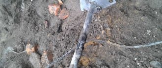
However, it can be difficult to determine the exact location of the cable route from them. Errors often occur due to the human factor.
But outdoor signs are not durable and are often damaged by unauthorized persons.
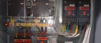
Moreover, even with a route finder, sometimes there are a lot of nuances in identifying a particular cable in dense urban areas.
The so-called “dirty air” is when communication cables or power cables laid in parallel, as well as communication pipes, generate significant interference.
Ultimately, the slightest mistake can result in huge costs and long-term equipment downtime.
To prevent this from happening, they came up with electronic marking of underground cable lines and other communication networks (each at its own frequency).
However, do not be confused, such intelligent marking is just an addition to existing methods of detecting and marking a route. And under no circumstances should we refuse them.
What is electronic tagging?
What is the essence of electronic cable marking? Everything is very simple. Initially during the construction period, a special marker is placed next to the existing communication line - an “orange” in a protective plastic casing.
This marker is easily determined from the surface of the earth with a sounding device. The search tool generates a signal, which causes response oscillations of a certain frequency in the marker, which are recorded on the screen.
These things are especially effective in places where couplings are installed and on road turns.
There is no need to apply any voltage to the marker or connect it to anything.
Imagine that from now on, when tracing a line, you no longer have to:
1Go to the transformer substation or substation to disconnect and unplug the ends of the cable. 2Switch the consumer to the backup cable line.
3Connect the generator to the conductors.
4Wander randomly around the city with headphones on and try to hear a squeak from the signal source among the extraneous noise.
5Dig a hole to find out the depth.
Your labor costs will be reduced by at least 50%. Here is a real calculation and comparison of similar work performed at one of the branches of OJSC “MOESK”.
The service life of the marker is 50 years and above. Individual specimens can be buried to a depth of 2.4 m and they will be perfectly audible.
True, it is always recommended to secure them with a cable to avoid movement when the ground moves.
The signal spot from them on the surface reaches 2 meters.
→ The procedure for determining the type of cable damage and choosing a method for finding it • Determining the distance to the location of the cable damage • Brief theory from IRK-PRO • Review of damage to cable insulation during the construction and operation of communication lines • Continuity of the cable line with telephone handsets • Measuring the electrical resistance of the circuit (loop) cable • Types of damage to the insulation of communication lines. Methods of calculation and search • Ohmic and capacitive asymmetry • Electrical capacitance. Finding breaks and brokenness • Measurement of coupling attenuation at the near end • Pulse method of cable measurement
The procedure for determining the type of cable damage and choosing a method for finding it
Instruments and methods used
• Telephone handset.
Used for testing and determining the nature of damage.
• Cable device.
This refers to PKP, IRK-PRO or any other class devices capable of measuring insulation resistance up to 30,000 MOhm, the electrical capacitance of cable cores and having bridge circuits for comparing resistances and capacitances.
• Line discontinuity meter or reflectometer
(practically this is the same thing). It can be made as part of the device from the previous paragraph, for example IRK-PRO-Alpha. The pulse cable measurement method is used.
• Crosstalk meter.
For example: IPZ-(the entire series), “Delta-PRO” and the like. They can also be made as part of a cable device.
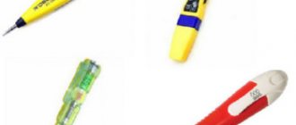
• Search kit
(router, cable locator). Used to search directly along the cable route. Must use inductive and contact search methods. It consists of at least two blocks: a generator and a search block.
Decide what you will be looking for
Even before approaching the cable terminal, you need to have a clear idea of where the cable begins, where it should end, and whether there are other terminal devices on this cable—parallels. In practice, little-known tie-ins and incorrectly twisted couplings are possible; tens and twenties in the private sector and in rural areas are especially guilty of this.
For cables in operation, an important, albeit indirect proof of the absence of little-known “chemicals” is the same inclusion of cross-connects on both terminal devices. That is, if 0, 3, 5, 8 pairs are turned on at the cable input, then they (0, 3, 5) should be used at the output. However, it is useful to check the presence of power on these pairs, otherwise installers do not always turn those wires that are not used.
For some idea of how all this can be damaged, see the page “Overview of damage to cable insulation during the construction and operation of communication lines”
Handset operation
Ways to find the right pair on the box.
Correct
: you should be informed by technical maintenance (cross) about which pair on the box is damaged. The first method works well on highways and with exemplary certification.
One of its variations is tracking the desired pair starting from the station. For example, knowing what pair number the desired number is in the trunk, we find it in the distribution cabinet and determine which pair it went into distribution or transmission.
Second
associated with cross. The cross-country worker connects to the damaged pair with his device, and you have to look for this inclusion with a handset on the box, connecting the handset to each pair in turn until this cross-country worker answers you.
Third
consists in the fact that you dial the number of the required subscriber (you can use a mobile phone) and use a screwdriver or other conductor to short-circuit all the pairs of the box one by one. When the required pair is short-circuited, the call signal will be interrupted in the handset.
The second and third methods are bad because they trigger an alarm
in neighboring classes and you have a chance to meet armed guys from the authorities.
Determining the type of damage
For measurements, it is necessary to identify broken conductors, conductors with the lowest insulation and conductors with high insulation (clean)
The sequence of actions when determining damage for operation differs somewhat from the same work in construction organizations due to the use of a paired container when connecting a cable line. Builders work with a clean cable, but for operation, it takes half a day to remove power from a 100-pair cable, and then another half a day will have to turn it all on. Add to this that more than 100 subscribers will find themselves without Internet and landline phone service per day.
For use.
Having disconnected the incoming and outgoing cross-connection from the pair under test, we make sure that the damage is in the desired cable (alas, the installer who submitted the damage to the cable must be checked).
If there is voltage on the pair after disconnection (the tube clicks on the ground-core circuit) - this is a message, a violation of the insulation to the other cable pair. Having determined that there is a message in the cable core, find which core it communicates with. To do this, connect the tube to the “ground - damaged core” circuit and short-circuit the remaining pairs of the cable one by one. At the moment the communicating pair is short-circuited, a loud click will be heard in the tube, and if several pairs click, choose the loudest one. Disconnect power from the found pair. The message should disappear or become smaller. Determine by measuring the insulation between the communicating conductors which conductor of this pair communicates.
Congratulate yourself, you have found the cores to measure with bridge circuits.
By definition, there cannot be a message in a single-pair cable (PRPPM, CAPS). Alas, I know a case where this happened - several PRPPMs were spliced together in a homemade coupling and filled with some kind of rubbish, the coupling became numb, and a message appeared on single-pair cables.
The ground of the tube is determined in operation using a supply wire of a different number. If the tube clicks on the power-core circuit when the pair is disconnected, then this is called “ground”. But it is useful for the meter to know that this can also be a message, only the message is not from the supply wire of the adjacent pair, but from the positive one (the supply wire is a minus).
A break is determined by the absence of a station response from the pair at the output end of the cable. Sometimes it is useful to look for broken wires on other pairs of the box, especially if the cable has recently been repaired.
To determine wiretapping (diversity or reduced transient attenuation), the same thing is used with a wiretap, although it only detects a transient of no more than 40 dB. The handset is connected to the pair being tested, and you don’t even have to turn off the power, but only by dialing one digit of the number. Next, alternately shortcut adjacent pairs with a screwdriver. If the pair is poorly protected, then clicks from the short will be heard in the tube, and the pair that is shorted is also affected. For more accurate measurements, instruments of the appropriate class are used.
About wiretapping or raznopark there are pages Measuring coupling attenuation at the near end and Security of pairs and quadruples in communication cables
For construction.
It is easier for builders because they are dealing with unoccupied (clean) cable. Without any disconnections, all its damage can be determined by a simple test. The trick here is to do this on one side or with a minimum number of trips between end devices. So, to determine breaks, you can ground all the conductors at one end of the cable and ensure the presence of grounding at the other end. Message and ground are determined at one end by the same tube or insulation measurement.
When making calls, you should pay more attention to the correct assembly of the cable, and if errors are found in the jointing of the plinths, or there is insufficient resoldering of the cores in the plinths, you should check the transient attenuation between the pairs of the plinth.
An important parameter when accepting a cable for operation is the insulation of the screen (proves the integrity of the sheath)
With a telephone handset you can determine all damage to the insulation and, with some understanding of the processes, even broken pairs (multiple pairs). A little more detail on the page “Dialing a cable line with telephone handsets.”
Continue on Determining the distance to the location of cable damage
Intelligent marking of underground utilities
But the main advantage of this technology is not the easier determination of the route location. Markers are not only passive, but also intellectual.
They have internal non-volatile memory based on an RFID chip. The chip is located on a plastic disk.
In some models, all this floats in a propylene glycol solution.
Why does it need to be placed in liquid? Firstly, this allows you to bury markers in frozen soils (without the risk of signal loss).
And secondly, it automatically aligns the disk to a horizontal position, regardless of which side you put the ball in the ground.
When placing this “buoy” you can write down all the necessary information, namely:
- type of communication
- voltage level
- specific name of the coupling or feeder
- cable line owner
- depth
- track turning angle
That is, from now on you simply move the marker finder to a given point, and instantly, without searching for drawings and documentation, directly “in the field” you receive all the information you are interested in about the cable.
Moreover, using the same marker finder, all previously recorded data can be edited and changed, which is called in real time. To do this, place the locator above the marker in the ground, select the appropriate menu items and enter all changes.
After all, within 50 years both the owner of the line and the feeder number may change. You won’t dig up a red buoy to add new data to it.
Editing occurs directly through the marker finder, even without connecting to a laptop.
An intellectual marker acts as a kind of “eternal” identification mark, but not externally, but underground. At the same time, vandals will never be able to purposefully damage it.
Locator kits for searching voltage-free cables and metal pipelines
The route-search kit detects, determines the depth and topology of communications that do not radiate on their own, including pipelines. The equipment consists of a receiver (locator), a generator (signal transmitter) and connecting elements. The generator supplies an electromagnetic signal to de-energized cables and metal pipelines. And the receiver picks up electromagnetic waves in specified frequency ranges created by the source of oscillations.
There are two modes of using the tracking kit - active and passive detection. In active detection mode, a generator is activated and the equipment is used to locate objects that do not emit radiation. With passive detection, only the device’s sensors work, which detect interference created by the current flowing through the desired communications.
Types of markers
What types of markers exist?
4 types are widely used:
- near-superficial or finger-like
Used if the cable lies shallow, immediately under asphalt or other covering. Reading depth – 0.6 m.
To install, just drill a hole with a diameter of 2 cm and stick a “finger” into it.
- minimarker
It is placed mainly in soft soils, when a full-fledged marker is considered an excessive solution due to the not very deep route (1.8 m).
- ball marker
The most common type of all markers for cables, couplings and other communications. It is in them that the principle of intelligence is applicable.
Detection depth is 1.2 m for intelligent models and 1.5 m for passive ones.
- full size marker
Used for deep-lying objects - 2.0-2.4 m.
At the same time, all markers are never buried flush with the track. As a rule, they extend 20cm above its level.
The markers differ in color and have their own signal frequency. This is done to recognize the type of communication:
- red – electrical cable
- orange – telecommunications, communications
- yellow – gas pipeline
- blue – plumbing
- black-orange – cable TV
Locator components
The electromagnetic locator consists of a lightweight portable heterodyne receiver, which provides high noise immunity and sensitivity, making it possible to work in conditions of strong external interference, with a weak signal level, in areas saturated with communications. The receiver has control buttons and a display on which the results of the locator search are displayed. The receiver can be powered by batteries or an electrical cable.
The communications being sought may be energized or de-energized. To search for de-energized communications, a compact generator (transmitter) is used - a source of electromagnetic pulses of a certain frequency. The generator can be connected to the pipe or cable being tested using terminals, or pulses can be transmitted into the communication in a non-contact manner.
To receive signals, antennas are used, one or more, of various designs and spatial orientations, which can also be rotated.
If you need to determine the position of a non-metallic pipe through which a liquid flows, and the pipe does not have a satellite wire, you can use special locators that are equipped with floating probe sensors, which, moving in the pipe along with the liquid, allow you to determine the location of the pipe. Similarly, video head locators with a miniature transmitter are used to locate damage and blockages in pipes. To determine the location of damage to a cable or pipe (and, accordingly, the location of electric current and water leaks), use contact probes buried in the ground, included with the device.
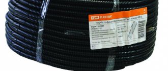
Smart warning tape
In addition to plastic markers, something similar is sewn directly into the signal tape. If round ones are mainly used at couplings, turns and intersections, then smart warning tape is used on straight sections in dense urban areas.
This tape is not afraid of tears and damage, unless, of course, you stick a shovel or something more serious directly into the marker itself.
Markers are built into the surface in clusters of 2 or 4 pieces each. The distance between clusters is 2 meters.
The signal is continuous due to mutual intersection. Unfortunately, the markers here are not intelligent and can only be used to determine the location of the cable without unnecessary details.
Tapes also have their own frequency depending on the type of communication. Detection depth underground – 60cm.
In this case, the recommended height of the laying directly above the communication route is 50 cm.
Power cables under load and pipelines with cathodic protection
In this case, a fairly large current flows through the cable. Flowing through the cable, the current forms an electromagnetic field, which is easily detected by the receiver in passive search mode. Such cables are looked for first and the probability of finding them is quite high. Most often, this is done by monitoring signals at frequencies of 50Hz (power cables), 100Hz (cathodic protection current of pipelines). To search for a power cable under load on the territory of the site, it is enough to turn on the locator receiver in passive mode and walk along the contour of the area under study. When a cable is detected, you can trace it based on the signal level and mark its location on the site.
Wire satellite
Someone may rightly point out why I need all this complexity; I can find my cable anyway by connecting the generator to the corresponding cores.
What if we are talking about communications without metal components? For example, polyethylene gas pipeline or fiber optic communication lines.
In such a situation, a satellite wire laid in parallel is usually used. Although this is not regulated in any way by current industry standards, it is widely used.
Most often, the cheapest wire of the PV 1*2.5 or PV 1*4 brand is used as a conductor.
At the same time, if we objectively compare all costs, and especially service life, then markers outright outperform such wires in all respects. Here you can familiarize yourself with already implemented projects and reviews on this technology.