Chromel-alumel type K
This is one of the most used types of thermocouples.
Over a long period of time it measures temperatures up to 1100 0C, in a short time – up to 1300 0C. Measuring low temperatures is possible down to -200 0C. Performs well in oxidizing atmospheres and inert conditions. Can be used in dry hydrogen, and briefly in a vacuum. Sensitivity – 40 µV/ 0С. This is the most resistant type of thermocouple capable of operating in reactive conditions. The disadvantages are high deformation of the electrodes and unstable EMF.
Chromel-alumel or K-type thermocouple are not used in environments containing more than 3% O2. With a higher oxygen content, chromium is oxidized and the thermal emf decreases. Type K with protective cover can be used in a variable redox atmosphere.
To protect the XA thermocouple, a shell made of porcelain, asbestos, fiberglass, quartz, enamel material or highly refractory oxides is used.
Most often, chromel-alumel fails due to the destruction of the alumel electrode. This happens after heating the electrode to 650 degrees in a sulfur environment. Corrosion of alumel can be prevented only by eliminating the entry of sulfur into the working environment of the thermocouple.
Chrome deteriorates due to internal oxidation when the atmosphere contains water vapor or high acidity. Protection is the use of ventilated protection.
Advantages and disadvantages of the Chromel-Kopel thermocouple
The Chromel-Kopel thermocouple is distinguished by its simplicity and reliability of design, and a relatively high degree of temperature measurement accuracy. Due to the fact that Chromel and Copel thermoelectrode wire has excellent thermoelectric properties, low inertia and high heat resistance, the thermocouple can be used in a wide variety of fields and environments. In addition, thermocouple wire has a low cost, which is important from an economic point of view for consumers. The only drawback of this type of thermocouple is its sensitivity to deformation, which, however, does not have any effect on the accuracy and quality of measurements.
Chromel-copel type L
It is also a commonly used thermocouple allowing measurements in inert and oxidizing environments.
Long-term measurement up to 800 0С, short-term – 1100 0С. The lower limit is -253 0C. Long-term operation up to 600C. This is the most sensitive thermocouple of all industrial-type measuring devices. Has linear graduation. At a temperature of 600 degrees it is distinguished by thermoelectric stability. The disadvantage is the increased susceptibility of the electrodes to deformation. The positive electrode of a type L thermocouple is chromel, and the negative electrode is kopel. The working medium is oxidizing or with an inert gas component. Can be used in vacuum at elevated temperatures for a short time. Using good gas-tight protection, THC can be used in sulfur-containing and oxidizing environments. Operation in a chlorine or fluorine-containing atmosphere is possible, but only up to 200 degrees.
Types of thermocouples and their characteristics
Different alloys used to make thermocouples have different thermo-EMF coefficients. Depending on what metals the thermoelectrodes are made of, the following main types of thermocouples are distinguished:
- TPP13 – platinum-rhodium-platinum (type R);
- TPP10 – platinum-rhodium-platinum (type S);
- TPR – platinum-rhodium-platinum-rhodium (type B);
- TFA – iron-constantan (type J);
- TMKn – copper-constantan (type T);
- TNN – nichrosil-nisil (type N);
- THA – chromel-alumel (type K);
- THCn – chromel-constantan (type E);
- THC – chromel-copel (type L);
- TMK – copper-copel (type M);
- TSS – sil-silin (type I);
- TVR – tungsten rhenium (types A-1 – A-3).
Technical requirements for thermocouples are set by parameters defined by GOST 6616-94, and their NSC (nominal static conversion characteristics), optimal measurement ranges, established tolerance classes are regulated by IEC 62460 standards, and defined by GOST R 8.585-2001. Let us also note that the NSC in tungsten-rhenium thermocouples was absent from the IEC tables until 2008. To date, these standards do not define the characteristics of the Chromel-Kopel thermocouple, but their parameters are still regulated by GOST R 8.585-2001. Therefore, imported L-type thermocouples are not a complete analogue of the domestic THC product.
Thermal sensors can also be classified according to other criteria: by type of junction, number of sensitive elements.
Types of junctions
Depending on the purpose of the temperature sensor, the thermocouple junctions may have different configurations. There are single-element and two-element junctions. They can be either grounded to the body of the bulb or ungrounded. You can understand the diagrams of such structures from Figure 5.
Rice. 5. Types of junctions
The letters indicate:
- And – one junction, isolated from the body;
- H – one junction connected to the body;
- AI – two junctions isolated from each other and from the housing;
- 2I – double junction, isolated from the housing;
- IN – two junctions, one of which is grounded;
- LV – two non-insulated junctions connected to the housing.
Grounding to the housing reduces the inertia of the thermocouple, which, in turn, increases the speed of the sensor and increases the accuracy of real-time measurements.
In order to reduce inertia, some models of thermoelectric converters leave a hot junction outside the protective flask.
Multipoint thermocouples
It is often necessary to measure temperature at different points simultaneously. Multipoint thermocouples solve this problem: they record temperature data along the axis of the transmitter. This need arises in the chemical and petrochemical industries, where it is necessary to obtain information about the temperature distribution in reactors, fractionation columns and other vessels intended for chemical processing of liquids.
Multipoint temperature measuring transducers increase efficiency and do not require complex maintenance. The number of data collection points can reach up to 60. In this case, only one flask and one entry point into the installation are used.
Iron constantan type J
Used in reducing, oxidizing, inert and vacuum environments.
Measurement of positive media up to 1100 0С, negative – up to -203 0С. It is type J that is recommended for use in a positive environment with a transition to negative temperature conditions. It is not recommended to use TFA only in a negative environment. Over a long period of time it measures temperatures up to 750 0C, in a short interval 1100 0C. Disadvantages: highly sensitive - 50-65 µV/0C, susceptible to deformation, low corrosion resistance of the electrode containing iron. The positive electrode of a type J thermocouple is commercially pure iron, and the negative electrode is a copper-nickel alloy constantan.
TFA is resistant to oxidizing and reducing environments. At temperatures above 770 0C, iron is susceptible to magnetic and ↔-transformations, which affect thermoelectric properties. The presence of a thermocouple in conditions greater than 760 0C is no longer capable of accurately measuring the temperature indicators of the numbers below. In this case, its readings do not correspond to the calibration table.
The service life depends on the cross-section of the electrodes. The diameter must correspond to the measured indicators.
At temperatures above 500C with sulfur content in the atmosphere, it is recommended to use a protective gas-tight cover.
Thermocouple stability
Numerous studies have shown higher stability of cable TCs compared to conventional wire ones. Thus, the change in readings of cable thermocouples of the XK type with a diameter of 4 mm (electrode diameter 0.85 mm) at 425 ± 10 ° C for 10,000 hours does not exceed 0.5 ° C, and for 25,000 hours is + 1.15 ° C, while for wire ones it reaches 1°C in 10,000 hours.
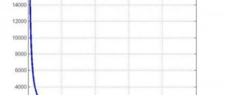
Comparative tests of XA type thermocouples showed that the change in thermo-emf. cable thermocouple with an outer diameter of 3 mm (thermoelectrode diameter 0.65 mm) at a temperature of 800°C for 10,000 hours is approximately 2.5°C, whereas for a conventional TXA thermocouple with thermoelectrodes with a diameter of 3.2 mm it reaches 3°C, and with a diameter electrodes 0.7 mm exceeds 200–250 μV (5-6°C) under the same conditions.
Change in thermo-emf. cable thermocouples in a shell made of high-nickel alloys at 980°C are also half as much as a conventional thermocouple at the same temperature in 5000 hours. The change in readings of a TXA wire thermocouple with electrodes with a diameter of 3.2 mm reaches 11°C in 1000 hours at a temperature of 1093° C, and at 1200°C - 12.5°C for 200 hours. The increased stability of cable thermocouples is explained by the difficulty of oxidation of thermoelectrodes due to the limited amount of oxygen inside the cable, as well as additional protection of thermoelectrodes from the influence of the working environment by a metal sheath and magnesium oxide.
| Change in thermo-emf. thermocouple cable: KTMS-XA (1) and thermocouple XA in the usual version (2) at 800°C. Electrode diameter – 0.7 mm | Change in thermo-emf. thermocouple cables KTMS-XA after heating in air at 800°C. The numbers in the figure are the diameter of the cables, mm |
Tungsten-rhenium type A-1, A-2, A-3
Excellent temperature measurements up to 1800 degrees.
In industry it is used to measure indicators of about 3000 0С. The lower limit is limited to 1300 0C. Can be used in argon, nitrogen, helium, dry hydrogen and vacuum environments. Thermo-EMF at 2500 0C - 34 mV for measuring devices made of alloys VR5/20 and VAR5 / VR20 and 22 mV, for thermocouples made of alloy VR10/20, sensitivity - 7-10 and 4-7 µV/ 0C.
TVR is characterized by mechanical stability even at high temperatures and copes with alternating loads and sudden thermal changes. It is easy to install and practically does not lose its properties when dirty.
Cons: low thermo-EMF production;
during irradiation, unstable thermo-EMF; drop in sensitivity at 2400 0 C or more.
More accurate results for VAR5/VR20 alloys are observed during long-term measurements, which is not so typical for VR5/20 alloys.
In TVR, electrodes are made of alloys VR5 - positive and VR20 - negative; VAR5 – positive and BP20 – negative or BP10 – positive and BP20 – negative electrode.
A slight presence of O2 can damage a tungsten-rhenium thermocouple. In an oxidizing environment they are used only in fast-flowing processes. Under conditions of strong oxidation, it instantly fails.
Sometimes this thermocouple can be used in high temperature furnace operation in conjunction with a graphite heating element.
Ceramics are used as electrode insulators. Beryllium oxide can be used as an insulator when the temperature affecting it does not exceed the melting point. When measuring values less than 1600 0C, the electrodes are protected with pure aluminum or magnesium oxide. The ceramic insulator must be calcined to be able to clean various impurities. In conditions of increased oxidation, covers made of metal and Mo-Re, W-Re alloys with coatings are used. The measuring device with iridium protection can be used briefly in air.
How does a Chromel-Kopel thermocouple work?
The operation of the Chromel-Kopel thermocouple is based on the thermoelectric effect, also known as the “Seebeck effect,” named after its discoverer Thomas Johann Seebeck (1770-1831). The essence of this effect is that if the contact points (junctions) of dissimilar and series-connected conductors are maintained at different temperatures, then a thermoelectric current arises in the formed closed circuit. By measuring the value of this current, taking into account the thermoelectric properties of the conductor material, you can find out the temperature of the measured medium.
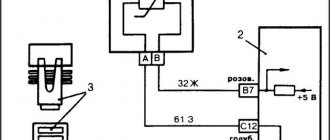
In order to measure the temperature of a substance using a Chromel-Kopel thermocouple, the working (hot) end of the thermocouple (3) is immersed in the substance being measured, and at the other (cold) end (1, 2) a constant temperature (usually 20 °C) is maintained at using a thermostat. Due to the temperature difference between compounds of dissimilar alloys, a potential difference arises and a thermoelectromotive force (TEMF) is generated, and an electric current arises in the circuit.
Chromel-Kopel thermocouple junction
The amount of current generated in the circuit is recorded by an electrical measuring device. Such a device can be a millivoltmeter or potentiometer. Typically, a current meter in thermocouples is equipped with a corresponding temperature scale, but if there is none, then after obtaining the current value, it is converted into heat units. In this way, the temperature of the substance being measured is determined with a relatively high degree of accuracy. The average temperature error is about ± 2-5 °C, but it can be more or less, which largely depends on the range of measured temperatures.
Tungsten-molybdenum
Operates in inert, hydrogen and vacuum environments.
Measurement temperatures – 1400 0С -1800 0С, operating limits – 2400 0С. Sensitivity - 6.5 µV/0C. Has high mechanical strength. Does not require chemical purity. Cons: low thermal emf; polarity inversion, increased brittleness at elevated temperatures.
Recommended for use in hydrogen, inert gas and vacuum environments. Oxidation in air occurs at 400 degrees. As the thermal feed increases, oxidation accelerates. TBM does not react with H and inert gas up to melting temperatures. It is better not to use this type of thermocouple without insulators, since it can react with oxides when the temperature rises. If there is a ceramic insulator, short-term use in an oxidizing environment is possible.
To measure the thermal component of the liquid metal, it is usually isolated with alumina ceramics using a quartz tip.
Applications of Chromel-Kopel thermocouples
The Chromel-Kopel thermocouple is mainly used in pyrometry, which is a set of non-contact (without contact of the thermoelectrode with the body) methods for measuring relatively high temperatures of various media. The main purpose of sensors on a chromel-copel thermocouple is continuous monitoring of temperature conditions in industrial and laboratory installations with temperatures from 200°C to 600°C. They measure the temperature of thermal radiation in kilns at ceramic factories, heated gases, flames, etc.
Chromel-Copel thermocouple (TCC)
Since bodies and liquids at high temperatures emit thermal energy and satisfy the requirements of pyrometry, the Chromel-Kopel thermocouple is used to measure the melting point of low-melting metals, which is usually below 600 °C. These include gallium (Mp 30 °C), cadmium (Mp 321 °C), bismuth (Mp 271 °C), thallium (Mp 303 °C), zinc (Mp 419 °C), indium (Mp 157 °C) , tin (melt 232 °C) and others. Such metals are most often used in electrical and radio engineering and must be of high quality, so compliance with the temperature regime for their melting is very important for the final result.
Platinum-rhodium-platinum types R, S
The most common types of thermocouples for temperatures up to 1600 0C.
These devices include platinum with an alloy of platinum and rhodium of 10% or 13% composition. Used in inert and oxidizing environments. Long-term use at 1400C, short-term use at 1600C. They have a linear thermoelectric property in the range of 600-1600 0C. The sensitivity indicator is 10-12 µV/0С (10% Rh) and 11-14 µV/С (13% Rh). They produce high-precision measurements, have high reproducibility and stability of thermo-EMF. Disadvantages: instability in the irradiated environment, increased sensitivity to contamination.
TPP with a good insulator can be used in reducing environments, and in conditions containing arsenic vapor, sulfur, lead, zinc and phosphorus.
They are practically not used for measuring negative temperatures due to reduced sensitivity. But, in a separate assembly it is possible to measure values up to -50 degrees. For values of 300-600 0C they are used as comparative indicators. Short-term use – up to 1600 0С, long-term use – 1400 0С. With protection, it can be used for a long time at 1500 0C.
Quartz and porcelain materials or mullite and sillimanite are used as insulators at temperatures up to 1200 0C. Reference thermocouples are insulated with fused quartz.
When used with a generated temperature of 1400 0C, it is better to use ceramics with Al2O3 oxide as an insulator. In a weakly oxidizing and reducing environment, about 1200 0C.
In weakly oxidizing and reducing conditions with temperatures above 1200 and regardless of conditions with temperatures above 1400 0C, it is necessary to use ceramic high-purity aluminum oxide as an insulator. In a reducing environment, magnesium oxide can be used.
Typically, the inner casing for a thermocouple consists of the same material from which the insulator is made. These materials must be gas-tight. In conditions of one-time temperature measurement of liquid steel, quartz tips are used to protect the working junction of the meter.
The entire working length of the electrodes must be insulated with a two-channel ceramic tube. The junction of the tube and the cover, the electrode and the tube must have gaps for ventilation. Electrodes must be thoroughly cleaned of grease before installation in the insulator. In turn, the metal case must also be dry and clean. All thermocouple components must be annealed before installation on site. Thermoelectrodes should not perform a supporting function for the insulator. This is especially important for vertical thermocouples.
5.6. Thermocouples. Part 2
A thermocouple made of tungsten and an alloy containing 75% W and 25% Mo can be used in the temperature range of 2000-3000 °C. Below 2000 °C it has a very low t.e.c. value.
Each high temperature thermocouple must be calibrated independently.
Thermocouples made of refractory non-metallic compounds are used relatively rarely in laboratory practice. The graphite-silicon carbide thermocouple (Fig. 98, a) has a thermal electrical power. 508 mV at 1700 °C and operational up to 2700 °C. Its service life is 115-120 hours, and the error is ±10 °C.
In an oxidizing atmosphere, the graphite rod 7 is destroyed due to the penetration of oxidizing gases through the walls of the SiC tube 4. When measuring temperatures above 1800 'C, the tube must be filled with argon or nitrogen. Thermocouple calibration Thermocouples are calibrated using the reference points of the International Practical Temperature Scale 1968 (MPTS-68) for a pressure of 101325 Pa (Table 13). J
Rice. 98. Graphite-silicon carbide thermocouple (a) and graph of the function V = f(t) for heating (b) and cooling (c) of the reference substance: 1 - graphite rod; 2 — Al2O3 plug, 3 — metallized contact; 4 - SiC tubes; 5 - SiC plug
Melting temperatures (tmelting points) in oC are taken as high-temperature reference points: Ni (1455), Pd (1554), Rh (1963), Ir (2447), W (3387). Thermocouple calibration is also carried out according to the melting point of substances that can be obtained in pure form: MnCl2*4H20 (58.089), naphthalene (80.3), iodoform CH13 (119.0), KNO3 (334.5), K2Cr207 (397.5 ), KC1 (771), NaCl (801.0) and K2SO4 (1069+3).
Calibration of thermocouples consists of plotting a graph V=f(τ), where τ is time (Fig. 98, b, c). The thermocouple in a protective case is immersed in the reference substance powder located in the crucible so that the thermocouple junction is located in the center of the mass of the reference substance. The crucible is placed in a crucible furnace and the temperature is slowly increased, noting the millivoltmeter readings every 20-30 seconds.
During the melting of the reference substance, the instrument readings do not change and a horizontal area appears on the graph V = f(τ) (see Fig. 98, c) corresponding to the melting temperature of the taken substance. Four or five such graphs are constructed, changing the reference substances. Then, based on the data obtained, a calibration curve is applied to graph paper, connecting the millivoltmeter readings for the areas of the V - Dm curves with the melting point of the reference substances used. Using the resulting calibration curve of this thermocouple, unknown temperatures are then found according to the millivoltmeter readings. After calibration, the millivoltmeter can no longer be changed. If it is known exactly what metals or alloys the thermocouple is made of, and there is a proven millivoltmeter, then the data in Table 1 is used to determine unknown temperatures. 8-12.
The correctness of plotting V = f(τ) is checked by cooling the melt of the reference substance and noting the millivoltmeter readings at regular intervals (see Fig. 98, b). The areas on the heating and cooling curves must correspond to the same millivoltmeter reading. True, a minimum may appear on the cooling curve (see Fig. 98, b) caused by supercooling of the melt, i.e. delay in the onset of crystallization of the substance. In addition, as the thermocouple junction moves away from the center of mass of the reference substance to the crucible wall, the size of the area on the heating and cooling curves, as a rule, decreases, which increases the calibration error of the thermocouple. The rate of heating and cooling of the crucible with the reference substance should not be more than 5-15 degrees/min.
It is convenient to record the curves V = f(τ) not from visual observations, but using self-recording instruments that allow continuous measurements.
In the temperature range from -30 to +300 °C, calibration of thermocouples can be carried out using a reference glass mercury thermometer. To do this, the “hot” junction of the thermocouple and the thermometer are placed in a test tube with silicone or mineral oil, which is immersed in a thermostat at a given temperature. After 5-10 minutes, record the readings of the galvanometer and thermometer. Then the temperature in the thermostat is changed and a new measurement is taken.
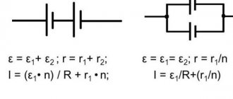
Differential thermocouples are used to measure temperature differences. The thermocouple consists of two branches 3 of the same conductor (Fig. 99, a), for example, from a constantan alloy, and a connecting copper wire 4, if you use a copper-constantan thermocouple. The “hot” junctions of the thermocouple are immersed in vessels 5 and 6 with different temperatures (t1noeq t2). The readings of galvanometer 1 will give the temperature difference t2~ 1\.
The “cold” junctions of the differential thermocouple do not have to be placed in Dewar flasks 2 with ice; it is enough that they have the same temperature.
Thermocouple battery. The sensitivity of measuring the temperature of an object using thermocouples can be significantly increased if they are combined into a battery (Fig. 99, b).
Figure 99 - Installation diagram with differential thermocouples (a) and thermocouple battery (b)
To create a battery, thermocouples are connected in series, placing all the “hot” junctions 3 in the place where the temperature K is measured, and the “cold” junctions 2, isolated from each other by small test tubes, are immersed in a Dewar flask with ice slurry (t = 0). The sensitivity of the battery increases approximately as many times as the thermocouples are taken, if we neglect the increase in the resistance of the entire circuit. The insulation of individual thermocouple junctions from each other must be reliable. Experimenters using a thermocouple bank often experience difficulties due to the appearance of stray currents of unknown origin. These currents can be reduced by thermally insulating the millivoltmeter and the conductors connecting it to the battery. Apparently, the appearance of parasitic currents is caused by non-homogeneity of the connecting wires (impurities, amorphous inclusions, mechanical stress, etc.).
Other parts:
5.6. Thermocouples. Part 1
5.6. Thermocouples. Part 2
To contents
Platinorhodium-platinumrhodium type B
Used in oxidizing and neutral conditions.
Operation in a vacuum environment is possible. The maximum measurement temperature for long-term flow is 1600 0C, short-term - 1800C. Sensitivity - 10.5-11.5 µV/0C. It is distinguished by good stability of thermal EMF. It can be used without extension wires due to low sensitivity in the temperature range from 0 to 100 0C. Made from an alloy of platinum and rhodium PR30 and PR6.
In a reducing atmosphere and vapors of metallic and non-metallic composition, reliable protection is necessary. Ceramic raw materials made of pure Al2O3 are used as an insulator.
The operating characteristics and strength data correspond to thermocouples of types R, S. However, they fail much less frequently due to their low susceptibility to chemical contamination and grain growth.