Capacitance of a capacitor
Capacitors are among the most common elements used in various electronic circuits. They are divided into types that have characteristic features, parameters and individual properties. The simplest capacitor consists of two metal plates - electrodes, separated by a dielectric layer. Each of them has its own terminal through which the connection to the electrical circuit is made.
Capacitance can be classified as reactive, which does not cause irreversible energy losses. The capacitor is charged to the voltage level supplied by the power source.
In a completely different way, the capacitor is affected by alternating current, which flows quite freely through the capacitance. This condition is explained by the constant processes of charging and discharging the element. In this case, not only the active resistance of the conductors acts, but also the capacitive reactance of the capacitor itself, which arises precisely as a result of its constant charging and discharging.
The electrical parameters and properties of capacitors may vary depending on various factors. First of all, they depend on the size and shape of the product, as well as on the type of dielectric. In different types of devices, the dielectric can be paper, air, plastic, glass, mica, ceramics and other materials. Electrolytic capacitors use aluminum electrolyte and tantalum electrolyte, which provides them with increased capacity.
The names of other elements are determined by the materials of conventional dielectrics. Therefore, they fall into the category of paper, ceramic, glass, etc. Each of them, in accordance with the characteristics and features, is used in specific electronic circuits, with different electric current parameters.
In this regard, the use of ceramic capacitors is necessary in those circuits where high-frequency noise filtering is required. Electrolytic devices, on the other hand, filter out interference at low frequencies. If you connect both types of capacitors in parallel, you get a universal filter that is widely used in all circuits. Despite the fact that their capacitance is a fixed value, there are devices with variable capacitance, which is achieved by adjustments by changing the mutual overlap of the plates. A typical example is tuning capacitors used in tuning electronic equipment.
What determines the resistance of capacitors in AC circuits?
Its indicators depend not only on the capacitive characteristics of the latter, but also on the frequency characteristics of the electric current flowing through the circuit. When we talk about the resistance of a resistor, we are talking about the parameters of the resistor itself, for example, material, shape, but there is absolutely no relationship between its resistance and the frequency indicators of the circuit electricity (we are talking about an ideal resistor, the parasitic parameters of which are not typical). When it comes to a device for storing energy and charging an electric field, everything is different. A capacitor of the same capacitance at different current frequencies has different levels of resistance. The amplitude of the electricity flowing through it at a constant voltage amplitude has a different value.
Considering this formula for the resistance of a capacitor in an alternating current circuit, what conclusions can be drawn? As the signal frequency increases, the electrical resistance of the capacitor decreases.
As the capacitive characteristics of the device for accumulating charge and energy of the electric field Xc of alternating electricity passing through it increase, it will tend downward.
The graph displaying this capacitor value for a variable circuit current has the shape of a hyperbola
The moment the frequency values approach zero marks on the axis (when the alternating electric current becomes similar in its parameters to constant), is accompanied by an increase in Xc of the capacitor to unlimited values. This is true: it is known that a DC mains capacitor is actually an open circuit. The actual electrical resistance, of course, is not infinite; it is limited by the level of capacitor leakage. But its values remain at a high level, which cannot be ignored.
As the frequency digits increase to the level of infinite values, the capacitance of the electric capacitor tends to zero. This characterizes ideal models. In real conditions, a capacitor has unpleasant characteristics (such as inductance and leakage resistances), so the capacitance decreases up to certain values, after which it increases.
Note! When a capacitor is connected to an electrical circuit with variable parameters, its power is not wasted, because the phase characteristics of voltage and current are shifted by 90° in relation to each other. In one quarter of the period, the electric capacitor is charged (energy is stored in its electric field), the next time it is discharged, the energy goes back into the circuit. Its electrical resistivity is watt-free and reactive.
Capacitance of a capacitor
Capacitors are among the most common elements used in various electronic circuits. They are divided into types that have characteristic features, parameters and individual properties. The simplest capacitor consists of two metal plates - electrodes, separated by a dielectric layer. Each of them has its own terminal through which the connection to the electrical circuit is made.
There are qualities unique to capacitors. For example, they do not allow direct current to pass through them at all, although they are charged by it. After the container is fully charged, the current flow stops completely, and the internal resistance of the device takes on an infinitely high value.
The capacitor is affected in a completely different way by flowing quite freely through the capacitance. This condition is explained by the constant processes of charging and discharging the element. In this case, not only the active resistance of the conductors acts, but also the capacitive reactance of the capacitor itself, which arises precisely as a result of its constant charging and discharging.
The electrical parameters and properties of capacitors may vary depending on various factors. First of all, they depend on the size and shape of the product, as well as on the type of dielectric. Different types of devices can be paper, air, plastic, glass, mica, ceramics and other materials. Electrolytic capacitors use aluminum electrolyte and tantalum electrolyte, which provides them with increased capacity.
The names of other elements are determined by the materials of conventional dielectrics. Therefore, they fall into the category of paper, ceramic, glass, etc. Each of them, in accordance with the characteristics and features, is used in specific electronic circuits, with different electric current parameters.
In this regard, the use of ceramic capacitors is necessary in those circuits where high-frequency noise filtering is required. Electrolytic devices, on the other hand, filter out interference at low frequencies. If you connect both types of capacitors in parallel, you get a universal filter that is widely used in all circuits. Despite the fact that their capacitance is a fixed value, there are devices with variable capacitance, which is achieved by adjustments by changing the mutual overlap of the plates. A typical example is tuning capacitors used in tuning electronic equipment.
Capacitive element
A capacitive element (consider the example of a capacitor) is a two-terminal network with a variable or constant capacitance value. A capacitor is a storage device for electrical charges. If you connect it to a power source, it will charge. If a source with a variable component is applied to it, it will charge when a positive half-cycle passes through it. When the direction of the half-cycle changes to a negative value, the capacitor will begin to recharge, that is, the energy that has accumulated in it will begin to counteract recharging. As a result, we get a voltage on the capacitor opposite to the source. As a result, I will lead U by some angle φ. Below is the result of modeling work on a C-R load C = 900 * 10 - 6 Fa, R = 0.5 Ohm, U source = 250 V, frequency f = 50 Hz.
Figure 2. Source operation on RC load
For container:
Where ω – cyclic frequency
— supply voltage frequency, Hz;
C is the capacitance of the capacitor;
Conclusion: the higher the capacitance C or frequency, the lower the resistance to alternating current will be.
Device characteristics
The most important characteristic of a storage device is capacity. The charging time depends on it when the device is connected to a power source. The discharge time is directly related to the value of the load resistance: the higher it is, the faster the process of releasing the accumulated energy occurs. This capacity is determined by the following expression:
C = E*Eo*S / d, where E is the relative dielectric constant of the medium (reference value), S is the area of the plates, d is the distance between them.
In addition to capacity, the capacitor is characterized by a number of parameters, such as:
- specific capacitance - determines the ratio of the capacitance to the mass of the dielectric;
- operating voltage - the nominal value that the device can withstand when applied to the plates of the element;
- temperature stability - the range in which the capacitance of the capacitor practically does not change;
- insulation resistance - characterized by the self-discharge of the device and determined by the leakage current;
- equivalent resistance - consists of losses generated at the terminals of the device and the dielectric layer;
- absorption - the process of the emergence of a potential difference on the plates after the device is discharged to zero;
- capacitance - a decrease in conductivity when alternating current is supplied;
- polarity - due to the physical properties of the material used in manufacturing, the capacitor can operate correctly only if a potential with a certain sign is applied to the plates;
- equivalent inductance is a parasitic parameter that appears on the contacts of the device and turns the capacitor into an oscillating circuit.
What's happened
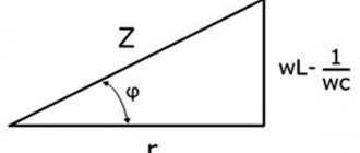
A circuit through which an intermittent current flows has total resistance. It is calculated by the sum of active and reactive resistance squared.
The graphic representation of this formula is a triangle. Its legs are represented by active and reactive resistance, and the hypotenuse is represented by total electrical resistance.
Capacitive electrical resistance (Xc) is one of the types of reactance. This indicator characterizes the resistance of the electrical capacitance in the circuit to electric current with variable parameters. The conversion of electricity into heat does not occur at the moment electricity flows through the container (reactance property). Instead, the energy of the electric current is transferred to the electric field and vice versa. There is no loss of energy during such an exchange.
The capacitance of a capacitor can be compared to a pan filled with liquid; when its volume is completely filled, it turns over, pouring out the contents, and then fills again. After reaching the maximum charge of the capacitor, it is discharged, then it is charged again.
Additional information: A circuit capacitor can only store a limited amount of charge before reversing the voltage polarity. For this reason, intermittent current does not drop to zero, an important difference from direct electricity. Low values of current frequency correspond to low values of charge accumulated by the capacitor, low values of resistance to electricity, which gives reactive properties.
Fazor
Thanks to phase vectors, a complex and time-varying signal can be represented as a complex number (independent of time) and a complex signal (dependent on time). Phasors are divided based on A (amplitude), v (frequency) and θ (phase). This is of great benefit, because the frequency coefficient is often common to all components of a linear combination of sinusoids. In such situations, the factors exclude the optional characteristic and are based only on A and θ.
For example, one can think of A⋅cos (2πνt + θ) simply as the complex constant Aeiθ. Due to the fact that phase vectors are transmitted by magnitude and angle, they are clearly represented by a vector in the xy plane.
The phasor can be viewed from the position of a vector rotating around the origin. The cosine function is the projection of the vector onto the axis. The amplitude acts as the modulus of the vector. Phase constant – the angle formed by the vector and the axis at t = 0
Examples of problem solving
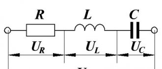
EXAMPLE 1
| Exercise | The oscillatory circuit has a resistance (R), an inductor (L) and a capacitor C (Fig. 1). An external voltage is connected to it, the amplitude of which is equal to , and the frequency is . What is the amplitude of the current in the circuit? |
| Solution | The circuit resistance in Fig. 1 consists of the active resistance R, the capacitance of the capacitor and the resistance of the inductor. The total resistance of a circuit (Z) that contains the above elements is found as: Ohm's law for our section of the circuit can be written as: Let us express the desired current amplitude from (1.2), substitute the right-hand side of formula (1.1) instead of Z, and we have: |
| Answer |
How to calculate Xc
The current strength of a circuit with constant voltage readings at the time of operation of the electric capacitor is equal to 0. Its value in a circuit with alternating voltage after connecting the capacitor I? 0. As a result, the capacitor imparts less Xc to a chain with a variable voltage than to a chain with a constant voltage.
Formula for calculating voltage in one second
Formula for calculating the amount of electric current in an instant
It turns out that voltage changes differ in phase from current changes by π/2.
According to the law formulated by Ohm, the strength of the electric current is directly proportional to the magnitude of the circuit voltage. Formula for calculating the largest values of voltage and current:
The highest values of voltage and current can be calculated using the formula
The final formula for calculating capacitance in an AC circuit
f is an indicator of the frequency of intermittent current, measured in hertz;
ω is an indicator of the angular frequency of the current;
Capacitor resistance to alternating voltage
When a capacitor is connected to an alternating current circuit, current flows freely through the capacitor. This can be explained very simply: a process of constant charging and discharging of the capacitor occurs. In this case, they say that the circuit contains capacitive reactance of the capacitor, in addition to active resistance.
And so, a capacitor, which is connected to an alternating current circuit, behaves as a resistance, that is, it affects the current flowing in the circuit. We denote the value of capacitance as , its value is related to the frequency of the current and is determined by the formula:
where is the frequency of alternating current; — angular frequency of current; C is the capacitance of the capacitor.
If a capacitor is connected to an alternating current circuit, then no power is expended in it, because the phase of the current is shifted relative to the voltage by . If we consider one period of current oscillation in the circuit (T), then the following happens: when the capacitor is charged (this amounts to ), energy is stored in the capacitor field; in the next period of time (), the capacitor discharges and releases energy into the circuit. Therefore, capacitive reactance is called reactive (watt-free).
It should be noted that in every real capacitor, real power (loss power) is still spent when alternating current flows through it. This is caused by changes occurring in the state of the dielectric of the capacitor. In addition, there is some leakage in the insulation of the capacitor plates, so a small active resistance appears, which is, as it were, connected in parallel with the capacitor.
Capacitance formula
In order to determine the capacitance in a particular circuit, you will need to identify the following parameters:
- Frequency of alternating current flowing in the circuit;
- Nominal capacitance value of the capacitor;
- The presence of other radio elements in the circuit.
After all the above factors are taken into account, it will be possible to determine the capacitance of the capacitor using the following formula:
Xс=1/ ω C.
This formula indicates the inversely proportional dependence of resistance on the value of capacitance and frequency of the supply voltage.
Due to this nature of its change, capacitors can operate in the following frequency-dependent circuits:
- Integral and differential devices;
- Resonant circuits of various classes;
- Special filter elements.
Let's add to this the possibility of using capacitors as damping elements in an alternating current circuit loaded on powerful (power) units.
Vector diagram of currents in a circuit with a capacitor
To determine the effective value of the total current I using the vector addition method, we construct a vector diagram according to the equation
I = IG + IC
Effective values of current components:
IG = GU (13.31)
IC = BCU (13.32)
The first on the vector diagram is the voltage vector U (Fig. 13.16, a), its direction coincides with the positive direction of the axis from which the phase angles are measured (initial voltage phase φa = 0). Vector IG coincides in direction with vector U, and vector IC is directed perpendicular to vector U with a positive angle. From the vector diagram it can be seen that the total voltage vector lags behind the total current vector by an angle φ, the value of which is greater than zero, but less than 90º. Vector I is the hypotenuse of a right triangle, the legs of which are its constituent vectors IG and IC:
At voltage u = Umsinωt, according to the vector diagram, the current equation
i = Imsin(ωt + φ)
About the charge of a capacitor.
Let's close the circuit. A capacitor charging current will flow through the circuit. This means that some electrons from the left plate of the capacitor will go into the wire, and the same number of electrons will go from the wire to the right plate. Both plates will be charged with opposite charges of the same magnitude.
There will be an electric field between the plates in the dielectric.
Now let's open the circuit. The capacitor will remain charged. Let's short-circuit its lining with a piece of wire. The capacitor will instantly discharge. This means that an excess of electrons will go from the right plate into the wire, and a lack of electrons will go from the wire to the left plate. There will be equal amounts of electrons on both plates, and the capacitor will discharge.
To what voltage does the capacitor charge?
About real capacitor
A real capacitor has two resistances at the same time: active and capacitive. They should be considered connected in series.
The voltage applied by the generator to the active resistance and the current flowing through the active resistance are in phase.
The voltage applied by the generator to the capacitance and the current flowing through the capacitance are shifted in phase by 90. The resulting voltage applied by the generator to the capacitor can be determined using the parallelogram rule.
At the active resistance, the voltage Uact and current I are in phase. At capacitive reactance, the voltage Uc lags the current I by 90. The resulting voltage applied by the generator to the capacitor is determined by the parallelogram rule. This resulting voltage lags behind the current I by some angle φ, always less than 90.
Complex resistance
The introduction of a complex representation of currents and voltages requires determining the resistance of the elements of electrical circuits in complex form - Z.
It is well known that the resistance of a resistor is defined as the ratio of the voltage across the resistor to the current flowing through it. If voltage and current are represented in complex form, then
But in the previous lecture it was established that. That's why
(3.1)
Thus we see that the complex resistance of the resistor is expressed only in a real number. It does not introduce phase distortions between currents and voltages. To emphasize this fact, such resistance is often called active.
The complex resistance of the capacitance is determined by the relation
. (3.2)
We see that the complex resistance of the capacitance to alternating current is expressed by an imaginary number. The imaginary unit -j physically determines the phase shift between current and voltage by 90°. This agrees well with its maximum value
Therefore, the voltage across the capacitor lags behind the current by 90°. This means that first the current flowing through the capacitor increases, then, with some lag, the charge and voltage increase.
The coefficient 1/ determines the resistance value in Ohms. It is inversely proportional to frequency, called capacitance and is designated XC, i.e.
. (3.3)
The complex inductance resistance is determined by the ratio
. (3.4)
And in this case, the resistance is expressed by an imaginary number. But since this number is positive, this means that the voltage at the inductance leads the current by 90°.
The wL coefficient determines the resistance value in Ohms. It is proportional to frequency, called inductive reactance and denoted XL, i.e.
. (3.5)
To emphasize the fact that the resistances of capacitance and inductance are expressed in imaginary numbers, they are called reactances, and the capacitor and inductance are called reactive circuit elements.
Let us now determine the complex resistance of an electrical circuit containing active and reactive elements, for example R, L and C elements connected in series (Fig. 3.1). Such a chain represents a closed circuit, therefore Kirchhoff’s second law is valid for it
. (3.6)
In the last expression, we will replace the symbols of instantaneous voltages and emf with their complex images according to the rules defined in lecture 1.2. This technique is called the symbolic method. Since the current flowing through all elements of the series circuit is the same, then (3.6) comes to the form
Let's transform this expression to the form
.
By definition, the expression on the right side of the last equality is nothing more than the complex resistance of the circuit in Fig. 3.1, i.e.
(3.7)
where R is the real part or active resistance of the circuit.
- imaginary part or reactance of the circuit.
Expression (3.7) represents the complex resistance in algebraic form. The relationships between the components of the complex resistance are in full accordance with the relationships for the complex representation of the current. But for greater clarity, the concept of a resistance triangle is introduced (Fig. 3.2).
In a triangle, the hypotenuse is determined by the modulus of complex resistance Z, and
(3.8)
The opposite leg has reactance X, and
(3.9)
The angle determines the phase shift between current and voltage, which is introduced by the complex resistance of the circuit, and
(3.10)
Taking into account expressions (3.8) ¸ (3.11) it is easy to move from the algebraic to the trigonometric form of complex resistance
Z (3.12)
a by applying Euler's formula to obtain the exponential form
Z (3.13)
Now you can write Ohm's law for a section of the circuit without an EMF source in a complex image
(3.14)
Expression (3.14) shows that in alternating current circuits the current modulus is determined by the ratio of the voltage modulus (its amplitude value) to the complex resistance modulus, and the current phase is determined by the difference in the phases of voltage and complex resistance. This leads to another useful expression for practice:
. (3.15)
Capacitance in an AC circuit
When a capacitor is connected to a DC circuit, a charging current will flow through the circuit for a short period of time. At the end of charging, when the capacitor voltage matches the voltage of the current source, the short-term flow of current in the circuit will stop. Thus, completely at constant current will be a kind of open circuit or resistance with an infinitely large value. With alternating current, the capacitor will behave completely differently. Its charging in such a circuit will be carried out alternately in different directions. The flow of alternating current in the circuit is not interrupted at this time.
A more detailed examination of this process indicates a zero voltage value in the capacitor at the moment it is turned on. After AC voltage is supplied to it, charging will begin. At this time, the mains voltage will increase during the first quarter of the period. As charges accumulate on the plates, the voltage of the capacitor itself increases. After the mains voltage reaches its maximum at the end of the first quarter of the period, charging stops and the current in the circuit becomes zero.
There is a formula for determining the current in a capacitor circuit: I = ∆q/∆t, where q is the amount of electricity flowing through the circuit during a period of time t. In accordance with the laws of electrostatics, the amount of electricity in the device will be: q = C x Uc = C x U. In this formula, C will be the capacitance of the capacitor, U will be the network voltage, Uc will be the voltage on the plates of the element. In its final form, the formula for the current in the circuit will look like this: i = C x (∆Uc/∆t) = C x (∆U/∆t).
When the second quarter of the period begins, the mains voltage will decrease and the capacitor will begin to discharge. The current in the circuit will change its direction and flow in the opposite direction. In the next half of the period, the direction of the mains voltage will change, the element will recharge, and then it will begin to discharge again. The current present in a circuit with a capacitor will be 90 degrees ahead of the phase voltage on the plates.
It has been established that changes in the capacitor current occur at a rate that is proportional to the angular frequency ω. Therefore, in accordance with the already known formula for the current in the circuit i = C x (∆U/∆t), it similarly turns out that the effective value of the current will also be a proportion between the rate of change of voltage and the angular frequency ω: I = 2π xfx C x U .
Next, it is quite easy to establish the value of capacitance or reactance of the capacitor: xc = 1/2π xfx C = 1/ ω x C. This parameter is calculated when the capacitor is connected to the alternating current circuit. Therefore, in accordance with Ohm’s law, in an alternating current circuit with a capacitor turned on, the current value will be as follows: I = U/xc, and the voltage on the plates will be: Uc = Ic x xc.
The part of the mains voltage that falls on the capacitor is called the capacitive voltage drop. It is also known as the reactive voltage component, denoted by the symbol Uc. The value of capacitive reactance xc, as well as the value of inductive reactance xi, is directly related to the frequency of alternating current.
DEFINITION
Capacitor
, in the simplest case, consists of two metal conductors (plates), which are separated by a dielectric layer. Each of the capacitor plates has its own terminal and can be connected to an electrical circuit.
A capacitor is characterized using a number of parameters (capacitance, operating voltage, etc.), one of these characteristics is resistance. The capacitor practically does not allow direct electric current to pass through. That is, the capacitor resistance is infinitely large for direct current, but this is the ideal case. A very small current can flow through a real dielectric. This current is called leakage current. Leakage current is an indicator of the quality of the dielectric used in the manufacture of the capacitor. With modern capacitors, the leakage current is several fractions of a microampere. The resistance of the capacitor in this case can be calculated using Ohm's law for a section of the circuit, knowing the voltage to which the capacitor is charged and the leakage current. But usually, when solving educational problems, the resistance of a capacitor to direct current is considered infinitely large.
Vector representation of capacity
Reactance
To get a clearer idea of what capacitance is, you can use the vector representation of the processes occurring in the capacitor.
Vector representation
After studying the diagram, you can notice that the current in the capacitor circuit changes phase ahead of the voltage by 90 degrees. From the nature of the interaction of basic electrical quantities, it is concluded that the capacitor resists changes in voltage across it.
The larger the capacitance, the slower it is recharged to full voltage (and the lower the capacitance of a given element). This conclusion completely coincides with the formula given earlier.
Additional Information. When examining inductances connected to alternating current circuits, the opposite pattern is discovered when the current, on the contrary, lags in phase with voltage changes.
Note that in both cases, the observed differences in the phase parameters indicate the reactive nature of the resistance of these elements.
Capacitance in AC circuit
When a constant voltage is applied to the capacitor, it will gradually charge to the maximum potential difference across its plates. After this, the current through the electronic component will stop and, apart from a negligible leakage, will be zero. Therefore, in a DC circuit, the capacitor has a huge resistance. In calculations, its value is taken equal to infinity.
Reactance has a completely quantifiable value. It can be measured using an oscilloscope, a generator and a fixed resistor. To do this you will need to assemble a circuit. In it, the capacitor forms a voltage divider with a resistor. An oscilloscope will be used to measure the potential that forms at the terminals of the capacitor.
For this scheme, the calculations are as follows.
Indirect measurement formula
Here:
- Ur – potential difference across the resistor, V;
- Uc – voltage on the plates, V;
- R – resistor resistance, ohm;
- Xc – capacitance resistance, ohm;
- I – current flowing in the circuit, A.
Indirect measurement
Important! The electrical cable also has a capacitance. Therefore, after removing the voltage, some charge remains on it
This phenomenon is dangerous for humans, especially if the conductor was at a potential of 1000 V or higher before disconnecting.
Capacitor charge formula
To perform charging, the capacitor must be connected to a DC circuit. A generator can be used for this purpose. Every generator has internal resistance. When the circuit is closed, the capacitor is charged. A voltage appears between its plates equal to the electromotive force of the generator: Uc = E.
The plate connected to the positive pole of the generator is charged positively (+q), and the other plate receives an equal charge with a negative value (-q). The amount of charge q is directly proportional to the capacitance of the capacitor C and the voltage on the plates Uc. This dependence is expressed by the formula: q = C x Uc.
During the charging process, one of the capacitor plates gains and the other loses a certain number of electrons. They are transferred through an external circuit under the influence of the electromotive force of the generator. This movement is an electric current, also known as charging capacitive current (Icharge).
The charging current flows in the circuit in almost thousandths of a second, until the moment the capacitor voltage becomes equal to the electromotive force of the generator. The voltage increases smoothly and then gradually slows down. Further, the capacitor voltage value will be constant. During charging, a charging current flows through the circuit. At the very beginning, it reaches its maximum value, since the capacitor voltage has a zero value. According to Ohm's law, Izar = E/Ri, since the entire emf of the generator is applied to the resistance Ri.
Capacitor resistance.
Let's close the circuit. The capacitor began to charge and immediately became a source of current, voltage, E.M.S.. The figure shows that the E.M.S. of the capacitor is directed opposite the current source charging it.
The opposition of the electromotive force of a charged capacitor to the charge of this capacitor is called capacitance.
All the energy expended by the current source to overcome capacitance is converted into the energy of the electric field of the capacitor. When the capacitor is discharged, all the energy of the electric field will return back to the circuit in the form of electric current energy. Thus, capacitance is reactive, i.e. not causing irreversible energy losses.
Why doesn't direct current pass through the capacitor, but alternating current does?
Let's turn on the DC circuit. The lamp will flash and go out, why? Because a capacitor charging current passed through the circuit. As soon as the capacitor is charged to the battery voltage, the current in the circuit will stop.
Now let's close the AC circuit. In the first quarter of the period, the voltage on the generator increases from 0 to maximum. The circuit carries a capacitor charging current. In the second quarter of the period, the voltage on the generator decreases to zero. The capacitor is discharged through the generator. After this, the capacitor is charged and discharged again. Thus, the charge and discharge currents of the capacitor flow through the circuit. The light will remain on continuously.
In a circuit with a capacitor, current flows throughout the entire closed circuit, including the dielectric of the capacitor. An electric field is generated in a charging capacitor which polarizes the dielectric. Polarization is the rotation of electrons in atoms in elongated orbits.
The simultaneous polarization of a huge number of atoms produces a current called displacement current.
Thus, current flows in the wires and in the dielectric of the same magnitude.
capacitor is determined by the formula
At active resistance, the voltage U act and current I are in phase. At capacitive reactance, the voltage Uc lags behind the current I by 90 0. The resulting voltage applied by the generator to the capacitor is determined by the parallelogram rule. This resulting voltage lags behind the current I by some angle φ, always less than 90 0.
Basic Concepts
Capacitive reactance is the value that is created by a capacitor connected to the circuit. The resistance of the supply wires should be non-negligibly large. When alternating current is supplied, processes arise due to the periodic charge and discharge of the capacitor.
The period is divided into four quarters. During the first quarter the tension increases. At this moment, a charging current passes through the circuit, the strength of which will decrease, reaching zero when the electromotive force reaches a positive maximum. The capacitor is fully charged. After this, the voltage drop will begin. The capacitor will be discharged through the load connected to it. Current will flow through the circuit.
By the end of the half-cycle, the voltage will be zero, and the current will be greatest. Discharging is complete. At the beginning of the third quarter, the electromotive force will increase, changing its direction. The charging process will begin again. The direction of the charging current in the third quarter will be the same as in the previous one. As the capacitor charges, this value will decrease. By the end of the third quarter, the charging process will be completed.
The electromotive force will reach its greatest negative value. And on the plate, which had a positive charge during the first half-cycle, there will now be a negative one. During the fourth quarter, the value of the electromotive force will again tend to zero. The capacitor will discharge. Accordingly, a gradually increasing current will appear in the circuit. The process is repeated. Thus, the AC phase in the capacitor circuit leads the voltage phase by 90 degrees.
About real capacitor
A real capacitor has two resistances at the same time: active and capacitive. They should be considered connected in series.
The voltage applied by the generator to the active resistance and the current flowing through the active resistance are in phase.
The voltage applied by the generator to the capacitance and the current flowing through the capacitance are shifted in phase by 90. The resulting voltage applied by the generator to the capacitor can be determined using the parallelogram rule.
At the active resistance, the voltage Uact and current I are in phase. At capacitive reactance, the voltage Uc lags the current I by 90. The resulting voltage applied by the generator to the capacitor is determined by the parallelogram rule. This resulting voltage lags behind the current I by some angle φ, always less than 90.
Inductive element L
An inductive element (let's look at an inductor as an example) consists of turns of wire insulated with each other. When current flows, the coil becomes magnetized. If you change the polarity of the source, the coil will begin to release the stored energy back, trying to maintain the amount of current in the circuit. Therefore, when a variable component flows through it, the energy accumulated during the passage of the positive half-cycle will not have time to dissipate and will prevent the passage of the negative half-cycle. As a result, the negative half-cycle will have to extinguish the energy stored by the coil. As a result, voltage (U) will lead current (I) by some angle φ. Below is the result of simulating operation on a LR load L=1*10 -3 H, R=0.5 Ohm. U source = 250 V, frequency f = 50 Hz.
φ is the phase difference between U and I.
Reactance is designated by the letter X, total Z, active R.
For inductance:
Where ω – cyclic frequency
L – coil inductance;
Conclusion: the higher the inductance L or frequency, the greater the coil's resistance to alternating current will be.
Connection of capacitors
Often a capacitor by itself is not enough. Therefore, such electronic components have to be combined into groups, so-called batteries. With this connection, many containers are connected to each other to obtain a new one with different characteristics.
There are 2 main ways to connect parts:
- consistent;
- parallel.
Series connection of containers
With this type of connection, many parts are lined up in a long chain (from two pieces or more). Most often in practice, combinations of 2-5 parts are used. Each previous one is connected to the next one. The result is a long chain, reminiscent of cars on a train.
Serial connection
Connecting capacitors in series reduces their total capacitance. This is due to the fact that the thickness of the dielectric between the plates of the device increases, while the area of their intersection remains unchanged (see formula above). How to calculate the total capacitance of a capacitor when connected in series can be found in the formula below.
Capacitance of series capacitors
In fact, such a connection is used to obtain a new capacitance value, but such a capacitor is simply not commercially available. For example, having two elements with a nominal value of 10 uF each and connecting them in series, you can get a total capacitance of 5 uF.
Example of sequential calculation
Another feature of series connection is the increase in total voltage. If you take 2 containers of 200 V each and connect them in the described way, then the final battery voltage will be 200 + 200 = 400 volts.
Voltage resonance in a series oscillating circuit
In radio engineering, electrical circuits consisting of an inductor and a capacitor are widely used. In radio engineering such circuits are called oscillatory circuits. An alternating current source can be connected to an oscillating circuit in two ways: in series (Figure 1a) and in parallel (Figure 1b).
Figure 1. Schematic designation of an oscillatory circuit. a) series oscillatory circuit; b) parallel oscillatory circuit.
Let's consider the behavior of an oscillatory circuit in an alternating current circuit when the circuit and a current source are connected in series (Figure 1a).
We know that such a circuit provides alternating current with a reactance equal to:
where R L is the active resistance of the inductor in ohms;
ωL , is the inductive reactance of the inductor in ohms;
1/ωC is the capacitance of the capacitor in ohms.
The active resistance of the coil R L practically changes very little when the frequency changes (if the surface effect is neglected). Inductive and capacitive reactance depend to a very large extent on frequency, namely: inductive reactance ωL increases in direct proportion to the frequency of the current, and capacitive reactance 1/ωC decreases with increasing frequency of the current, i.e. it is related to the frequency of the current in inverse proportion.
It immediately follows that the reactance of a series oscillatory circuit also depends on frequency, and the oscillatory circuit will provide unequal resistance to currents of different frequencies.
If we measure the reactance of the oscillating circuit at different frequencies, we will find that in the low frequency region the resistance of the series circuit is very high; as the frequency increases, it decreases to a certain limit, and then begins to increase again.
This is explained by the fact that in the region of low frequencies the current experiences high resistance from the capacitor, but as the frequency increases, inductive reactance begins to act, compensating for the effect of capacitive reactance.
At a certain frequency, the inductive reactance becomes equal to the capacitive reactance, i.e.
They will cancel each other out and the total reactance of the circuit will become zero:
In this case, the reactance of the series oscillatory circuit will be equal only to its active resistance, since
With a further increase in frequency, the current will experience more and more resistance from the inductance of the coil, while the compensating effect of capacitance decreases. Therefore, the reactance of the circuit will begin to increase again.
Figure 2a shows a curve showing the change in the reactance of a series oscillatory circuit when the current frequency changes.
Figure 2. Voltage resonance. a) dependence of the change in impedance on frequency; b) dependence of reactance on the active resistance of the circuit; c) resonance curves.
The frequency of the current at which the resistance of the oscillating circuit becomes the smallest is called the resonance frequency or resonant frequency of the oscillating circuit.
At the resonant frequency the equality holds:
using which it is easy to determine the resonance frequency:
(1)
The units in these formulas are hertz, henry and farad.
From formula (1) it is clear that the smaller the capacitance and self-inductance of the oscillatory circuit, the greater will be its resonant frequency.
The value of active resistance RL does not affect the resonant frequency, but the nature of the change in Z . Figure 2b shows a series of graphs of changes in the reactance of the oscillatory circuit for the same values of L and C , but for different RL . From this figure it can be seen that the greater the active resistance of the series oscillatory circuit, the dumber the reactance change curve becomes.
Now let's look at how the current strength in the oscillatory circuit will change if we change the frequency of the current. In this case, we will assume that the voltage developed by the alternating current source remains the same all the time.
Since the current source is connected in series with L and C of the circuit, the current flowing through the coil and capacitor will be greater, the lower the reactance of the oscillatory circuit as a whole, since
It immediately follows that at resonance the current strength in the oscillatory circuit will be greatest. The magnitude of the current at resonance will depend on the voltage of the AC source and on the active resistance of the circuit:
Figure 2d shows a series of graphs of changes in current strength in a series oscillatory circuit when the current frequency changes, the so-called resonance curves . From this figure it can be seen that the greater the active resistance of the circuit, the dumber the resonance curve.
At resonance, the current can reach enormous values with a relatively low external emf . Therefore, voltage drops across the inductive and capacitive resistances of the circuit, i.e., across the coil and across the capacitor, can reach very large values and far exceed the magnitude of the external voltage.
The last statement may seem somewhat strange at first glance, but you need to remember that the phases of the voltages on the capacitive and inductive reactances are shifted relative to each other by 180°, i.e., the instantaneous voltage values on the coil and capacitor are always directed in opposite directions. As a result, large voltages that exist during resonance inside the circuit on its coil and capacitor do not reveal themselves outside the circuit, mutually compensating each other.
The case of series resonance that we have analyzed is called voltage resonance , since in this case, at the moment of resonance, there is a sharp increase in voltage on L and C of the oscillatory circuit.
DID YOU LIKE THE ARTICLE? SHARE WITH YOUR FRIENDS ON SOCIAL NETWORKS!
Related materials:
- Coil inductive reactance
- Inductor in an AC circuit
- Capacitor in an alternating current circuit. Capacitance of a capacitor.
- AC circuit resistance
- AC circuit impedance
- Resonance phenomenon
- Ohm's law for alternating current
- Resonance of currents in a parallel oscillatory circuit
- Pulsating current
- Non-sinusoidal current
Comments
Ani 06/03/2019 15:06 Thank you, otherwise everywhere they stupidly push with mathematical calculations and forget about the physics of the phenomenon.
Quote
MIKE 07/01/2017 07:25 how to download a complete complex program for drawing and creating microcircuits?
Quote
Update list of comments