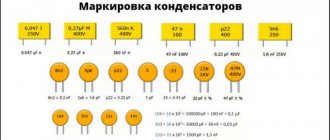
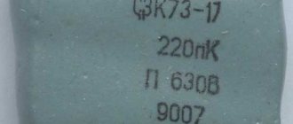
1. Marking with three numbers.
In this case, the first two digits define the mantissa and the last one defines the base 10 exponent to give the picofarad value. The last digit “9” denotes the exponent “-1”. If the first digit is “0”, then the capacitance is less than 1pF (010 = 1.0pF).
| code | picofarads, pF, pF | nanofarads, nF, nF | microfarads, μF, μF |
| 109 | 1.0 pF | ||
| 159 | 1.5 pF | ||
| 229 | 2.2 pF | ||
| 339 | 3.3 pF | ||
| 479 | 4.7 pF | ||
| 689 | 6.8 pF | ||
| 100 | 10 pF | 0.01 nF | |
| 150 | 15 pF | 0.015 nF | |
| 220 | 22 pF | 0.022 nF | |
| 330 | 33 pF | 0.033 nF | |
| 470 | 47 pF | 0.047 nF | |
| 680 | 68 pF | 0.068 nF | |
| 101 | 100 pF | 0.1 nF | |
| 151 | 150 pF | 0.15 nF | |
| 221 | 220 pF | 0.22 nF | |
| 331 | 330 pF | 0.33 nF | |
| 471 | 470 pF | 0.47 nF | |
| 681 | 680 pF | 0.68 nF | |
| 102 | 1000 pF | 1 nF | |
| 152 | 1500 pF | 1.5 nF | |
| 222 | 2200 pF | 2.2 nF | |
| 332 | 3300 pF | 3.3 nF | |
| 472 | 4700 pF | 4.7 nF | |
| 682 | 6800 pF | 6.8 nF | |
| 103 | 10000 pF | 10 nF | 0.01 µF |
| 153 | 15000 pF | 15 nF | 0.015 µF |
| 223 | 22000 pF | 22 nF | 0.022 µF |
| 333 | 33000 pF | 33 nF | 0.033 µF |
| 473 | 47000 pF | 47 nF | 0.047 µF |
| 683 | 68000 pF | 68 nF | 0.068 µF |
| 104 | 100000 pF | 100 nF | 0.1 µF |
| 154 | 150000 pF | 150 nF | 0.15 µF |
| 224 | 220000 pF | 220 nF | 0.22 µF |
| 334 | 330000 pF | 330 nF | 0.33 µF |
| 474 | 470000 pF | 470 nF | 0.47 µF |
| 684 | 680000 pF | 680 nF | 0.68 µF |
| 105 | 1000000 pF | 1000 nF | 1 µF |
2. Marking with four numbers.
This marking is similar to that described above, but in this case the first three digits determine the mantissa, and the last is the exponent in base 10 to obtain the capacitance in picofarads. For example:
1622 = 162*10 2 pF = 16200 pF = 16.2 nF
.
3. Alphanumeric marking.
With this marking, the letter indicates the decimal point and designation (uF, nF, pF), and the numbers indicate the capacitance value:
15p = 15 pF, 22p = 22 pF, 2n2 = 2.2 nF, 4n7 = 4.7 nF, μ33 = 0.33 µF
It is often difficult to distinguish the Russian letter “p” from the English “n”.
Sometimes the letter R is used to indicate the decimal point. Typically, capacitances are marked in microfarads, but if the letter R is preceded by a zero, then these are picofarads, for example:
0R5 = 0.5 pF, R47 = 0.47 µF, 6R8 = 6.8 µF
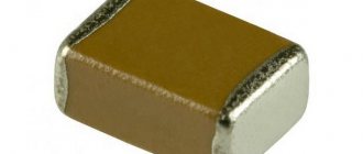
4. Planar ceramic capacitors.
Ceramic SMD capacitors are usually not marked at all except for color (I don’t know the color marking, if anyone can tell you, I’ll be glad, I only know that the lighter the capacitance, the smaller the capacity) or are marked with one or two letters and a number. The first letter, if present, indicates the manufacturer, the second letter indicates the mantissa in accordance with the table below, the number is an exponent in base 10, to obtain the capacitance in picofarads. Example:
N1 / we determine the mantissa from the table: N = 3.3 / = 3.3 * 10 1 pF = 33 pF
S3 /according to the table S=4.7/ = 4.7*10 3 pF = 4700 pF = 4.7 nF
| marking | meaning | marking | meaning | marking | meaning | marking | meaning |
| A | 1.0 | J | 2.2 | S | 4.7 | a | 2.5 |
| B | 1.1 | K | 2.4 | T | 5.1 | b | 3.5 |
| C | 1.2 | L | 2.7 | U | 5.6 | d | 4.0 |
| D | 1.3 | M | 3.0 | V | 6.2 | e | 4.5 |
| E | 1.5 | N | 3.3 | W | 6.8 | f | 5.0 |
| F | 1.6 | P | 3.6 | X | 7.5 | m | 6.0 |
| G | 1.8 | Q | 3.9 | Y | 8.2 | n | 7.0 |
| H | 2.0 | R | 4.3 | Z | 9.1 | t | 8.0 |
5. Planar electrolytic capacitors.
Electrolytic SMD capacitors are marked in two ways:
1) Capacitance in microfarads and operating voltage, for example: 10 6.3V = 10 µF at 6.3V.
2) A letter and three digits, where the letter indicates the operating voltage according to the table below, the first two digits determine the mantissa, the last digit is the exponent in base 10, to obtain the capacitance in picofarads. The stripe on such capacitors indicates the positive terminal. Example:
, according to table “A” - voltage 10V, 105 is 10 * 10 5 pF = 1 µF, i.e. this is a 1uF capacitor at 10V
| letter | e | G | J | A | C | D | E | V | H (T for tantalum) |
| voltage | 2.5 V | 4 V | 6.3 V | 10 V | 16 V | 20 V | 25 V | 35 V | 50 V |
Read also: Reuleaux triangle in a circle
Non-polar electrolytic capacitor
Non-polar electrolytic capacitors can find use in equipment designed for DC power supply, where polarity reversal can easily occur when the plug is turned on.
Dry non-polar electrolytic capacitors have two anode foils molded into the same electrolyte at the same voltage. The manufacturing technology of such capacitors is no different from the manufacturing of polar capacitors. Some change in technology takes place when winding sections, since instead of the cathode foil, a second anode plate is laid.
| Appearance of electrolytic capacitors. |
Non-polar electrolytic capacitors are also manufactured, in which both plates have an oxide layer.
Capacitors assembled as non-polar electrolytic capacitors can also be used for inclusion in an alternating current circuit.
Along with polar ones, there are dry non-polar electrolytic capacitors.
The industry also produces several types of non-polar electrolytic capacitors, in which the oxide layer is deposited on both electrodes.
Capacitance and dissipation tangent measurements of non-polar electrolytic capacitors and AC electrolytic capacitors are performed using the same methods as measurements of polar electrolytic capacitors. For these measurements, applying a DC polarizing voltage to the capacitors is not necessary.
As was shown in the fourth chapter, the capacitance of a non-polar electrolytic capacitor with the same plate area is half the capacitance of a conventional polar electrolytic capacitor.
Along with conventional polar capacitors, non-polar electrolytic capacitors can also be manufactured, in which a second anode is used instead of a cathode.
The polarity of high level signals must be unambiguous, or non-polar electrolytic capacitors must be used.
Capacitors with such plates do not require polarity when connected to an electrical circuit; Accordingly, they are called non-polar electrolytic capacitors.
As will be shown below, it is also possible to manufacture non-polar electrolytic capacitors, which do not require polarity when connected to a DC circuit. The production of a non-polar electrolytic capacitor designed for long-term operation at alternating voltage is hampered by the large tg 8 characteristic of capacitors of this type.
| Charge distribution in a non-polar electrolytic capacitor. a - at the moment when the voltage passes through a maximum, b - at the moment when the voltage is zero. |
Thus, only half of the total charge that was bound at the boundaries of the oxide layer when the voltage across the capacitor was at its maximum value can go into the external circuit. This circumstance leads to the fact that the capacitance of a non-polar electrolytic capacitor is half that of a polar capacitor that has the same anode surface as each plate of the non-polar capacitor.
Making a non-polar capacitor from a polar one
There may be several reasons for the abnormal use of electrolytes, ranging from the lack of non-polar capacitors to the need to assemble a circuit that ensures the connection of a three-phase electric motor to a single-phase network.
The problem can be solved by connecting two electrolytes back-to-back as shown in the figure below. Both elements must have the same capacitance and rated voltage.
An example of connecting two electrolytes for operation in an alternating current circuit
It should be taken into account that the total capacity of such connection “C” will be half of the specified value of the elements “C1” and “C2”. That is, if there are two electrolytes of 10 μF each, we will get a non-polar electrolytic capacitor of 5 μF (taking into account the permissible error of 4 μF - 4.7 μF). As for voltage, it is necessary to take into account the amplitude of the alternating current, that is, for a 220 Volt circuit, you should select elements with a rated voltage of at least 400 Volts.
The above circuit is not perfect, it can be slightly modernized by shunting the capacitors with diodes as shown in the figure below, this will provide protection against breakdown.
Adding Bypass Diodes
The above principle can be used to replace a failed starting capacitor for an electric motor. We do not recommend making such a replacement for sound, since electrolytes, like ceramic containers, due to their characteristics, are tried not to be used in audio equipment.
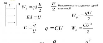
Flat capacitor and its capacity
A parallel plate capacitor is a capacitor that consists of two identical plates that are parallel to each other. The plates can be of different shapes. In practice, you can most often find square, rectangular and round plates. Let's look at a simple flat square capacitor.
flat capacitor
Where
d – distance between the capacitor plates, m
S – area of the smallest plate, m2
ε – dielectric constant of the dielectric between the plates of the capacitor
The finished formula for a flat capacitor will look like this:
Where
C – capacitor capacity, f
ε – dielectric constant of the dielectric
ε0 – dielectric constant, f/m
S – area of the smallest plate, m2
d – distance between plates, m
Yes, I know, the question immediately arises in your mind: “What is the dielectric constant?” The dielectric constant is a constant value that is needed for calculations in some electromagnetism formulas. Its value is 8.854 × 10⁻¹² f/m.
Dielectric constant - this value depends on the type of dielectric that is located between the plates of the capacitor. For example, for air and vacuum this value is 1; for some other substances you can look at the table.
What conclusion can be drawn from this formula? If you want to make a capacitor with a huge capacity, make the area of the plates as large as possible, the distance between the plates as small as possible, and use distilled water instead of the dielectric.
Currently, capacitors are made from several plates in the form of a layer cake. It roughly looks like this.
multilayer capacitor
In this case, the formula of such a capacitor will take the form:
multilayer capacitor formula
where n is the number of plates
What is a capacitor?
A device that stores electricity in the form of electrical charges is called a capacitor.
The amount of electricity or electric charge in physics is measured in coulombs (C). Electrical capacitance is calculated in farads (F).
A solitary conductor with an electrical capacity of 1 farad is a metal ball with a radius equal to 13 radii of the Sun. Therefore, a capacitor includes at least 2 conductors, which are separated by a dielectric. In simple device designs, paper is used.
The operation of a capacitor in a DC circuit is carried out when the power is turned on and off. Only during transient moments does the potential on the plates change.
The capacitor in the AC circuit recharges at a frequency equal to the frequency of the power source voltage. As a result of continuous charges and discharges, current flows through the element. A higher frequency means the device recharges faster.
The resistance of the circuit with a capacitor depends on the frequency of the current. At zero frequency of direct current, the resistance value tends to infinity. As the AC frequency increases, the resistance decreases.
What properties does a capacitor have?
The main characteristic of a capacitor
is its capacitance, which characterizes
the capacitor’s
to accumulate electrical charge.
The designation of a capacitor
indicates the value of the nominal capacitance, while the actual capacitance can vary significantly depending on many factors.
Interesting materials:
How to install Google Play on Huawei y6p? How to install Google Play on Samsung? How to install Google Play on Sony TV? How to install Google services on Huawei P Smart 2022? How to install Google services on Huawei P40? How to install Gwent on Android? How to install Gwent on PC? How to install Half-Life 2 on Android? How to install Half-Life 2? How to install Hangouts on your phone?
What is the difference between a polar and non-polar capacitor
The main difference between these two types is the structure of the dielectric, more precisely, its interface with the plate. For clarity, we suggest looking at Figure 1, which shows a non-polar ceramic capacitor.
Figure 1. Construction of a ceramic container in an SMD package
Designation of structural elements:
- A – contact electrodes;
- B – coating;
- C – dielectric;
- D – internal electrodes.
As can be seen from the figure, the boundary between the dielectric and the plate is homogeneous, and, accordingly, the interaction between them is the same. Therefore, this type of element does not require polarity during installation.
As for electrolytic (polar) capacitors, the structure of the transition between the plate and the dielectric is different for each side of the latter (cathode and anode). Moreover, the differences are expressed both in physical properties and chemical composition. As an example, let's look at how tantalum electrolytic containers are designed.
Polar type tantalum capacitor design
Designations:
- A – mark marking the anode contact;
- B – anode contact plate;
- C – internal anode based on granulated tantalum; the oxide of this chemical element (Ta2O5), formed during operation, acts as a dielectric;
- D – manganese dioxide electrolyte (MnO2);
- E – internal cathode (a mixture of silver and graphite);
- F – silver-based adhesive connecting the internal cathode to the contact plate;
- G – cathode contact plate;
- H – compound coating.
When installing this type of container, polarity must be observed. Otherwise, the element will not perform its functions. Therefore, electrolytic containers can only be used in a direct current (or pulsed) circuit. The use of alternating voltage in the circuit is also permissible if the inclusion of electrolytes meets certain conditions. We will discuss below whether it is possible to replace the electrolyte with a non-polar container.
How to check a capacitor with a tester on a board
The tracks and pads on modern boards are becoming smaller and smaller, and the boards themselves are often multi-layered. All this greatly complicates the process of disconnecting an element in order to monitor its performance. Therefore, the question becomes relevant: how to check a capacitor with a multimeter without desoldering it? Let's try to find a solution.
If the device works, then the problem really was in the capacitor and it needs to be replaced. The element is charged, then a metal tool with insulated handles is used to short-circuit its terminals.
Therefore, it is necessary to make sure that the circuits of the capacitor being measured are not influenced by such elements. If a transistor or diode is included in circuits with a capacitor, then during the measurement you can see the needle deflecting to a certain position and falling to a certain value equal to the resistance of the semiconductor junctions.
And if there is no short circuit, then the capacitor may be serviceable. You can make an attachment for the tester yourself using diagrams published in magazines and on the Internet. But they cannot always measure accurately due to the influence of other circuit elements. For example, several capacitors installed in parallel will eventually show the total capacitance.
Our electrical networks are not characterized by stable parameters, which often leads to equipment failure. Most often, rectifier bridge diodes and capacitors fail.
In this article we will talk about how to check a capacitor with a multimeter, how to understand that it has failed. As you know, capacitors have a certain capacity and serve to accumulate and short-term storage of electrical charge.
The larger the capacitor capacity, the longer the time required to accumulate charge. Essentially, these are all the properties that are worth knowing to test a capacitor with a multimeter. It is not difficult to find out whether a working capacitor is working or not. All you need is a multimeter. It can be inexpensive. The main thing is the worker. If we talk about types, the method of production of capacitors does not affect the verification.
They check the performance of paper, thin-film, electrolytic, liquid, ceramic, solid-state and all others, in exactly the same way.
For non-polar ones, the position of the probes can be any. It’s probably also worth saying how to identify polar capacitors. These are always electrolytic polar containers, which usually look like small barrels. On the polar ones, one of the terminals has a stripe of a contrasting color on the body.
If the body is white, the stripe is black, if the body is black, the stripe is white and light gray. This stripe marks the negative terminal minus.
Before testing a capacitor with a multimeter, inspect its housing. If there is no stripe, you don’t have to think about the position of the probes. To determine a damaged capacitor, you don’t even always need instruments. An external examination is often sufficient. A sign that the container is out of order is swelling of the body and streaks of any color.
Features of the design and inclusion of NEC
Electrolytic capacitor
A distinctive feature of such products is the absence of a constant displacement of electron masses on the plate elements. This is achieved due to the fact that aluminum parts undergo oxidation on both sides of the dielectric.
Design
Due to their structural features, the devices under consideration can be compared to a pair of back-to-back polar electrolytic cells that have no charge on the plating surfaces. Therefore, when such a capacitor is connected to a circuit, there is no need for a rigid connection to the potentials. Thus, these products are able to function in different parts of the electrical circuit and maintain the required capacitance parameters.
Features of inclusion
If you switch the positive and negative terminals when connecting a polarized device, it will not be able to charge and discharge. Therefore, such an element will not work normally. Non-polar electrolytic devices are capable of operating when connected to different circuits without regard to polarity. This is due to their structure - they do not have an anode and a cathode (plates with negative and positive charges).
In addition to electrolytic devices, there is another type of non-polar devices. Their design includes a pair of covering surfaces (without polarization) with a dielectric mounted between them. In electrical circuits, such parts are placed in the role of low-capacity elements with the functions of dividing the current into components, blocking and setting time.
Polymer (solid state) capacitors
Rice. 8. Polymer (solid-state) capacitors
Description: Solid capacitors are polarized like other electrolytic capacitors but have several advantages such as lower losses due to low series resistance ESR and long lifespan. For conventional aluminum electrolytes, there is a risk of the electrolyte drying out at low temperatures, but solid-state capacitors, due to the use of a solid polymer dielectric, are highly reliable even at very low temperatures.
Applications: Used as a replacement for electrolytes in high-end motherboards and DC/DC converters.
Kinds
"Electrolytes" are divided into the following types of elements:
- aluminum;
- tantalum;
- niobium.
Each type is designed for specific operating conditions.
Aluminum Electrolytic Capacitors (EC)
Aluminum EC includes two tapes of aluminum foil and paper impregnated with electrolyte. All this is rolled up and placed in a metal case. The dielectric in this part is aluminum oxide. To increase the surface area, the foil is etched in a live electrolyte. At the same time, the capacity increases many times. The structure is hermetically sealed with rubber gaskets.
For your information. The second strip of foil is needed to improve contact with the electrolyte (cathode) and to form a negative terminal.
Tantalum capacitors
The size of such ECs is small, which allows them to be used in surface-mounted printed circuit boards. Tantalum is used as an anode. It has a porous structure and gives a large working area. The dielectric is tantalum oxide – Ta2O5. The layer is formed by placing the workpiece in a high-temperature acid solution, after which a current is passed through it. By adjusting the current, the thickness of the film is controlled. The cathode is manganese dioxide. The workpiece is soaked in a solution of Mn(NO3)2 (manganese nitrate) and dried.
Interesting. The cathode terminal is made by covering a layer of manganese dioxide with graphite, which, in turn, is covered with a layer of silver. After that, a tap is soldered to the silver to install the element leads into the holes on the board. When manufacturing polar SMD capacitors, the lead-contact is molded from silver-plated epoxy resin.
Tantalum EC
Niobium capacitors
In cells of this type, niobium is used as the anode. The rest of the technology and properties of such two-terminal devices are similar to their tantalum counterparts.
Niobium EC
Polar and non-polar capacitors - what is the difference
All kinds of capacitors, used today almost everywhere in electronics and electrical engineering, contain various substances as dielectrics
However, with regard specifically to electrolytic capacitors, in particular also tantalum and polymer ones, when they are included in the circuit, it is important to strictly observe polarity. If such a capacitor is connected incorrectly to the circuit, it will not be able to work normally.
These capacitors are therefore called polar capacitors. What is the fundamental difference between a polar capacitor and a non-polar one? Why is it that some capacitors do not care how they are included in the circuit, while for others it is fundamentally important to maintain polarity?
Let's try to figure this out now. The point here is that the manufacturing process for electrolytic capacitors is very different from, say, ceramic or polypropylene. If for the latter two both the plates and the dielectric are homogeneous in relation to each other, that is, there is no difference in the structure at the plate-dielectric interface on both sides of the dielectric, then electrolytic capacitors (cylindrical aluminum, tantalum, polymer) have a difference in the structure of the dielectric transition -plating on both sides of the dielectric: the anode and cathode differ in chemical composition and physical properties.
When an electrolytic aluminum capacitor is made, they do not simply roll up two identical foil plates lined with electrolyte-impregnated paper. On the side of the anode plate (to which + is applied) there is a layer of aluminum oxide applied to the etched surface of the foil in a special way. The anode is designed to give electrons through an external circuit to the cathode during the charging of the capacitor. The negative plate (cathode) is simply aluminum foil; during the charging process, electrons come to it through an external circuit. The electrolyte here serves as a conductor of ions.
Polar and non-polar capacitors.
The same is the case with tantalum capacitors, where tantalum powder serves as the anode, on which a film of tantalum pentoxide is formed (the anode is connected to the oxide!), which functions as a dielectric, then there is a layer of semiconductor - manganese dioxide as an electrolyte, then a silver cathode, from which electrons will leave during the discharge process.
Polymer electrolytic capacitors use a lightweight conductive polymer as the cathode, but otherwise the processes are similar. The essence is oxidation and reduction reactions, like in a battery. The anode is oxidized during the electrochemical discharge reaction, and the cathode is reduced.
When an electrolytic capacitor is charged, there is an excess of electrons at its cathode, on the negative plate, imparting a negative charge to this terminal, and at the anode, a lack of electrons, giving a positive charge, thus obtaining a potential difference. If a charged electrolytic capacitor is connected to an external circuit, then excess electrons will run from the negatively charged cathode to the positively charged anode, and the charge will be neutralized. In the electrolyte, positive ions move at this moment from the cathode to the anode.
If such a polar capacitor is connected incorrectly to the circuit, then the described reactions will not be able to proceed normally, and the capacitor will not work normally. Non-polar capacitors can operate in any connection, since they have neither an anode, nor a cathode, nor an electrolyte, and their plates interact with the dielectric in the same way as with the source.
Capacitor polarity.
But what if you only have polar electrolytic capacitors at hand, but you need to connect the capacitor to a current circuit with changing polarity? There is one trick for this. You need to take two identical polar electrolytic capacitors and connect them together in series with terminals of the same name. You will get one non-polar capacitor from two polar ones, the capacitance of which will be 2 times less than each of its two components.
On this basis, by the way, non-polar electrolytic capacitors are made, in which an oxide layer is present on both plates. For this reason, non-polar electrolytic capacitors are significantly larger than polar capacitors of similar capacity. Based on this principle, electrolytic starting non-polar capacitors are also manufactured, designed to operate in alternating current circuits with a frequency of 50-60 Hz.
Polar and non-polar capacitor
The whole truth about capacitors: the magical properties of mysterious jars
Was there a better time to be a hi-fi enthusiast and lover than the late 1970s and early 1980s? On the one hand, there was so much happening with the development of digital audio, and on the other hand, there was an increase in subjectivity. Suddenly, turntables and amplifiers were judged not by their knock levels, output power, and harmonic distortion, but by how they sounded! And we could even talk seriously about the sound of the cables. In this new climate, everything that was once taken for granted in the field of hi-fi has become a candidate for re-evaluation.
The influence of passive electronic components - resistors, inductors and capacitors - on the sound has also been closely studied. Especially capacitors. Knowledgeable people began to discuss such phenomena as equivalent series resistance (ESR) and dielectric absorption.
Today we don't often hear about this topic, but not because the problem has been settled. Most likely, developers are now paying as much attention to the passive components they use as they are to the circuits in which they are used, so the public furor has died down somewhat.
Basics
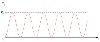
In its simplest form, a capacitor consists of two metal plates separated by air (or, better yet, vacuum) and is shown schematically in Fig. 1. Since there is no conductive path between the plates, the capacitor blocks direct current (from a battery, for example). In this case, the capacitor, on the contrary, transmits alternating current signals - just such as sound waves.
Rice. 1. The components that make up a capacitor are two conducting plates separated by a dielectric layer.
Proven Solution
We don't often come across air capacitors, but if you've looked inside an old tube radio and seen the tuning element made up of alternating metal plates, that's a variable air capacitor. Most capacitors we encounter in audio and other electronics do not use air as the insulating material (dielectric) separating the plates because it has a low dielectric constant (1.0), meaning that air capacitors have a high capacitance too bulky to be practical. For this reason, mainly solid dielectrics with higher dielectric properties are used, including ceramics and various types of plastics (for example, PVC with a dielectric constant of 4.0). This is where the story gets especially interesting, since all of these dielectrics have some compromise in terms of their effect on sound, while air is almost perfect.
Simple filters
First, let's learn more about how capacitors behave and what they are used for. Capacitors block direct current and allow alternating current to pass, but they do not pass alternating current at different frequencies equally. This is explained by the fact that capacitors have reactance, which decreases with increasing frequency (by the way, inductors also have reactance, which, on the contrary, increases with increasing frequency).
Thus, capacitors pass high-frequency signals more easily than low-frequency signals, making them extremely useful in frequency-selective circuits (i.e., filters) and also for eliminating unwanted signals (such as hum or noise from a DC power supply).
Simple high- and low-pass filters are shown in Fig. 2. In a high-pass filter (Fig. 2a), a capacitor in series is connected to a shunt resistor. In the low pass filter (Figure 2b), the capacitor and resistor are swapped.
Rice. 2. RC filter of the first order of high (2a) and low (2b) frequencies.
So, capacitors are often used to combine circuits, isolate unwanted noise in DC circuits and in frequency selective circuits (filters). Because capacitors store electrical charge, large ones are also used as reservoirs in AC and DC power supplies. In Fig. Figure 3 shows a typical power supply that includes a step-down transformer (which steps down the line voltage), a bridge rectifier (which converts the AC current from the transformer to pulsed DC current), and a pair of reservoir capacitors (which smooth out the ripple after the AC is rectified).
Fig.3. Schematic diagram of a full-wave power supply consisting of a step-down transformer, a full-wave bridge rectifier and two reservoir capacitors.
Similar circuits are found in many solid-state audio components. Similar solutions are used in lamp equipment, but due to the high voltages required to operate the lamps, the transformer here usually increases the mains voltage.
Reservoir capacitors used in transistor power amplifiers can be as large as 50,000 microfarads or more, while in other applications the circuit may use capacitors of 1 NF (one-thousandth of a microfarad) or even less. Thus, it is obvious that some types of capacitors are better suited for certain tasks than others.
Important clarification
As a rule, the largest reservoir capacitors are electrolytic, because they provide high capacity in a relatively small volume. These capacitors contain an electrolyte (liquid or gel) that chemically reacts with the metal foil inside the can to form a dielectric layer. Such electrolytic capacitors, as well as some others - for example, tantalum, are called polar, and failure to comply with the polarity of the connection can lead to their failure.
Another type is non-polar capacitors, which can be connected without regard to polarity. Such electrolytes were sometimes used in passive speaker crossovers, but this practice is now outdated as film capacitors do a better job, although they take up more space.
Capacitors can also have different pin arrangements - axial (axial) or radial. The advantage of radial electrolytes is that they occupy less area on the board, but their disadvantage is that they increase its height. Large electrolytic capacitors typically do away with solder pins in favor of screw terminals.
What do capacitors hide?
Real capacitors, like real capacitors, do not behave perfectly, and this is where the reason for their impact on sound quality lies. First, in practice, no capacitor is only a capacitance - it also has inductance and resistance. On a circuit diagram, a capacitor is usually indicated by one of the symbols in Fig. 4 (all of which visually refer to two separated plates), but in reality it is something like the circuit shown in Fig. 5. The resistor indicated in the figure as ESR (equivalent series resistance) may not be constant - the resistance may depend on frequency. In the case of electrolytic capacitors, ESR generally decreases with frequency.
Rice. 4. Options for designating capacitors in the diagram
One consequence of capacitors having inductance (ESL or equivalent series inductance in Figure 6) is that they are essentially electrically resonant. If we analyze the impedance of a capacitor as a function of frequency, it does not continue to decrease as frequency increases. In Fig. Figure 6 shows that the impedance reaches a minimum (equivalent to the ESR value) at the resonant frequency, and then, as the frequency increases, it begins to rise again due to ESL.
Rice. 5. Schematic equivalent of a real capacitor showing parasitic resistance (ESR) and inductance (ESL)
Rice. 6. Parasitic inductance causes capacitors to have electrical resonance, sometimes within the audible frequency range.
Large electrolytic capacitors typically have electrical resonance frequencies within the audio range. For small capacitors, electrical resonance frequencies can exceed 1 MHz. To increase the frequency of electrical resonance for a given capacitance, the ESL - series inductance - should be reduced.
To achieve this goal, various methods are used in the development of electrolytic capacitors, where this problem is most acute. For example, DNM T-Network capacitors use special foil T-junctions to reduce inductance - thus their resonant frequency is more than twice as high as a standard design (from 28 kHz to 75 kHz in the example given DNM on its website).
ESR has a potentially beneficial effect on damping the electrical resonance of a capacitor, however, unlike inductance or capacitance, resistance generates heat while current flows through the capacitor. In large capacitors, where the currents passing through them are large, this internal heating effect limits safe operating conditions. However, electrolytic capacitors work best when warm.
Microphone effect
It's no secret that lamp equipment is sensitive to vibration. Inside the evacuated glass shell of the lamp are thin metal electrodes, the distance between which affects the operation of the lamp. Thus, if you shake the lamp hard enough, it will affect its electrical output - an effect that is called "microphoning" because the lamp then behaves like a microphone.
Solid-state electronics are less susceptible to this effect, but to take one extreme example, the designers of early racing car engine management systems soon learned not to attach the electronic components to the engine, or to use good insulation, otherwise vibrations from the engine could interfere with its operation. The levels of vibration experienced by hi-fi equipment in everyday use are much lower, but some manufacturers, such as Naim Audio, still go to great lengths to minimize the likelihood of microphonic effects.
A capacitor's ability to store charge (its capacitance) is proportional to the area of the plates and inversely proportional to the distance between them, and the "plates" are usually thin foil with thin layers of dielectric between them. This causes capacitors to be susceptible to microphonic effects, as vibration can cause the distance between the plates and therefore the capacitance value to change.
Thus, the physical properties of the materials from which the capacitor is made can be as important as the electrical parameters. But what's even more interesting is that external vibration is not a necessary condition for capacitors to suffer from its effects, because forces generated by voltages and currents within the capacitor itself can also cause mechanical resonances. Because of this effect, you can even hear some capacitors making a sound when a signal passes through them. In a speaker crossover, where vibration levels, voltages, and currents are high, there is a “perfect storm” of factors that make selecting the appropriate capacitor a particularly important task.
Keywords
The problem of microphonic effect and mechanical resonances of capacitors has been actively discussed for many years, but there has been very little research on this issue. In any case, there are few published studies. But those that do exist support the view that this effect can have a noticeable impact on sound quality.
Additionally, in some cases, capacitors can produce unusually high levels of harmonic and intermodulation distortion. Understanding how and why this happens allows designers to focus their efforts on refining the circuitry and carefully selecting electronic components in a manner that will provide the greatest benefit.
General information
Capacitors are designed to store electrical energy and release it when necessary. These passive electronic components are divided into types:
- constant capacitor;
- variable capacitor.
The main characteristic of the element is capacity. It is designated by the letter C and is measured in farads.
Important! A unit of capacity 1 F is a very large value. Parts used in practice have capacitance measured in microfarads (µF), picofarads (pF), nanofarads (nF)
The graphic designation on the diagrams looks like two parallel vertical lines separated by a space.
The device of a capacitive two-terminal network of constant and variable capacitance
This is exactly how a conventional capacitor is designed. Between the two plates (plates) there is an air gap - a dielectric. The capacity value directly depends on the size of the plates and the distance between them.
The operation of variable capacitors is based on changing the distance between the plates. The moving plates are the rotor, the stationary plates are the stator. There are vacuum variable capacitive elements. The device is placed in a flask from which air has been pumped out.
Graphic designation on diagrams
Life Test Results of Electrolytic Capacitors
Double-terminal circuits of the same batch and the same type are tested. They are located in a thermostat in which the operating temperature is maintained. A current is passed through the elements, the voltage value of which is equal to Unom. The connection is made in the correct polarity. Separately, parts are tested by passing an alternating current of a given frequency and amplitude. During the test, all main and parasitic parameters are periodically monitored.
Based on the results, a calculation is made of the durability and number of hours without failures. An excellent result is 1 failure per hour for a batch of 1 billion parts.
Parameters that characterize capacitors
Generally speaking, there are many such parameters. We are not having a Nobel lecture here, so we will limit ourselves to only the necessary minimum, which will be useful in practical activities. Rated operating voltage. The capacitor can be used in modes when the voltage across it does not exceed the operating voltage. For example, you can use an electrolytic capacitor with an operating voltage of 10 V in +5 V or +3 V circuits.
The higher the operating voltage of an electrolytic capacitor with equal capacity, the larger its dimensions. The operating voltage on ceramic and other capacitors may not be explicitly stated or not stated at all - especially if the capacitor is small. ESR (Equivalent Series Resistance) - equivalent series resistance. The capacitor terminals and their contacts with the plates have non-zero, although very small, resistance. This resistance is active, therefore, in accordance with Ohm's and Joule-Lenz's laws, when current flows through this resistance, heat will be dissipated.
Marking of capacitors.
This will cause the capacitor to heat up. Therefore, electrolytic capacitors usually indicate the maximum operating temperature. Computer power supplies and motherboards use special capacitors with reduced ESR. The ESR value for such capacitors can range from hundredths to tenths of an Ohm. What happens if instead of a capacitor with a reduced ESR when repairing power supplies or motherboards, you use a regular one? It will work for a while. But since its ESR is greater, more current will flow through the circuit of such a capacitor, which will cause accelerated degradation of the capacitor. Therefore, it will quickly fail.
The ESR value can be determined by special markings (most often 2 Latin letters) on the capacitor body. The correspondence of these letters to real ESR values is indicated in the datasheet.
Code marking, addition
According to IEC standards, in practice there are four ways to encode the nominal capacity.
A. 3-digit marking
The first two digits indicate the capacitance value in pygofarads (pf), the last one indicates the number of zeros. When the capacitor has a capacitance of less than 10 pF, the last digit may be "9". For capacitances less than 1.0 pF, the first digit is “0”. The letter R is used as a decimal point. For example, code 010 is 1.0 pF, code 0R5 is 0.5 pF.
| Code | Capacitance [pF] | Capacitance [nF] | Capacitance [µF] |
| 109 | 1,0 | 0,001 | 0,000001 |
| 159 | 1,5 | 0,0015 | 0,000001 |
| 229 | 2,2 | 0,0022 | 0,000001 |
| 339 | 3,3 | 0,0033 | 0,000001 |
| 479 | 4,7 | 0,0047 | 0,000001 |
| 689 | 6,8 | 0,0068 | 0,000001 |
| 100* | 10 | 0,01 | 0,00001 |
| 150 | 15 | 0,015 | 0,000015 |
| 220 | 22 | 0,022 | 0,000022 |
| 330 | 33 | 0,033 | 0,000033 |
| 470 | 47 | 0,047 | 0,000047 |
| 680 | 68 | 0,068 | 0,000068 |
| 101 | 100 | 0,1 | 0,0001 |
| 151 | 150 | 0,15 | 0,00015 |
| 221 | 220 | 0,22 | 0,00022 |
| 331 | 330 | 0,33 | 0,00033 |
| 471 | 470 | 0,47 | 0,00047 |
| 681 | 680 | 0,68 | 0,00068 |
| 102 | 1000 | 1,0 | 0,001 |
| 152 | 1500 | 1,5 | 0,0015 |
| 222 | 2200 | 2,2 | 0,0022 |
| 332 | 3300 | 3,3 | 0,0033 |
| 472 | 4700 | 4,7 | 0,0047 |
| 682 | 6800 | 6,8 | 0,0068 |
| 103 | 10000 | 10 | 0,01 |
| 153 | 15000 | 15 | 0,015 |
| 223 | 22000 | 22 | 0,022 |
| 333 | 33000 | 33 | 0,033 |
| 473 | 47000 | 47 | 0,047 |
| 683 | 68000 | 68 | 0,068 |
| 104 | 100000 | 100 | 0,1 |
| 154 | 150000 | 150 | 0,15 |
| 224 | 220000 | 220 | 0,22 |
| 334 | 330000 | 330 | 0,33 |
| 474 | 470000 | 470 | 0,47 |
| 684 | 680000 | 680 | 0,68 |
| 105 | 1000000 | 1000 | 1,0 |
* Sometimes the last zero is not indicated.
B. 4-digit marking
4-digit coding options are possible. But even in this case, the last digit indicates the number of zeros, and the first three indicate the capacity in picofarads.
| Code | Capacitance[pF] | Capacitance[nF] | Capacitance[uF] |
| 1622 | 16200 | 16,2 | 0,0162 |
| 4753 | 475000 | 475 | 0,475 |
C. Capacitance marking in microfarads
The letter R may be used instead of the decimal point.
| Code | Capacitance [µF] |
| R1 | 0,1 |
| R47 | 0,47 |
| 1 | 1,0 |
| 4R7 | 4,7 |
| 10 | 10 |
| 100 | 100 |
D. Mixed alphanumeric marking of capacity, tolerance, TKE, operating voltage
Unlike the first three parameters, which are marked in accordance with standards, the operating voltage of different companies has different alphanumeric markings.
| Code | Capacity |
| p10 | 0.1 pF |
| IP5 | 1.5 pF |
| 332p | 332 pF |
| 1NO or 1nO | 1.0 nF |
| 15H or 15n | 15 nF |
| 33H2 or 33n2 | 33.2 nF |
| 590H or 590n | 590 nF |
| m15 | 0.15uF |
| 1m5 | 1.5 µF |
| 33m2 | 33.2 µF |
| 330m | 330 µF |
| 1mO | 1 mF or 1000 μF |
| 10m | 10 mF |
Code marking of electrolytic capacitors for surface mounting
The following coding principles are used by such well-known companies as Hitachi and others. There are three main coding methods:
A. Marking with 2 or 3 characters
The code contains two or three characters (letters or numbers) indicating the operating voltage and rated capacity. Moreover, the letters indicate voltage and capacitance, and the number indicates the multiplier. In the case of a two-digit designation, the operating voltage code is not indicated.
| Code | Capacitance [µF] | Voltage [V] |
| A6 | 1,0 | 16/35 |
| A7 | 10 | 4 |
| AA7 | 10 | 10 |
| AE7 | 15 | 10 |
| AJ6 | 2,2 | 10 |
| AJ7 | 22 | 10 |
| AN6 | 3,3 | 10 |
| AN7 | 33 | 10 |
| AS6 | 4,7 | 10 |
| AW6 | 6,8 | 10 |
| CA7 | 10 | 16 |
| CE6 | 1,5 | 16 |
| CE7 | 15 | 16 |
| CJ6 | 2,2 | 16 |
| CN6 | 3,3 | 16 |
| CS6 | 4,7 | 16 |
| CW6 | 6,8 | 16 |
| DA6 | 1,0 | 20 |
| DA7 | 10 | 20 |
| DE6 | 1,5 | 20 |
| DJ6 | 2,2 | 20 |
| DN6 | 3,3 | 20 |
| DS6 | 4,7 | 20 |
| DW6 | 6,8 | 20 |
| E6 | 1,5 | 10/25 |
| EA6 | 1,0 | 25 |
| EE6 | 1,5 | 25 |
| EJ6 | 2,2 | 25 |
| EN6 | 3,3 | 25 |
| ES6 | 4,7 | 25 |
| EW5 | 0,68 | 25 |
| GA7 | 10 | 4 |
| GE7 | 15 | 4 |
| GJ7 | 22 | 4 |
| GN7 | 33 | 4 |
| GS6 | 4,7 | 4 |
| GS7 | 47 | 4 |
| GW6 | 6,8 | 4 |
| GW7 | 68 | 4 |
| J6 | 2,2 | 6,3/7/20 |
| JA7 | 10 | 6,3/7 |
| JE7 | 15 | 6,3/7 |
| JJ7 | 22 | 6,3/7 |
| JN6 | 3,3 | 6,3/7 |
| JN7 | 33 | 6,3/7 |
| JS6 | 4,7 | 6,3/7 |
| JS7 | 47 | 6,3/7 |
| JW6 | 6,8 | 6,3/7 |
| N5 | 0,33 | 35 |
| N6 | 3,3 | 4/16 |
| S5 | 0,47 | 25/35 |
| VA6 | 1,0 | 35 |
| VE6 | 1,5 | 35 |
| VJ6 | 2,2 | 35 |
| VN6 | 3,3 | 35 |
| VS5 | 0,47 | 35 |
| VW5 | 0,68 | 35 |
| W5 | 0,68 | 20/35 |
B. 4-character marking
The code contains four characters (letters and numbers) indicating the capacity and operating voltage. The first letter indicates the operating voltage, the subsequent digits indicate the nominal capacitance in picofarads (pF), and the last digit indicates the number of zeros. There are 2 options for encoding the capacity: a) the first two digits indicate the nominal value in picofarads, the third - the number of zeros; b) the capacitance is indicated in microfarads, the m sign acts as a decimal point. Below are examples of marking capacitors with a capacity of 4.7 μF and an operating voltage of 10 V.
Read also: Large stapler how to change staples
C. Two-line marking
If the size of the case allows, then the code is located in two lines: the capacitance rating is indicated on the top line, and the operating voltage is indicated on the second line. Capacitance can be indicated directly in microfarads (µF) or in picofarads (pf) indicating the number of zeros (see method B). For example, the first line is 15, the second line is 35V - means that the capacitor has a capacity of 15 uF and an operating voltage of 35 V.
This article was produced by our experienced team of editors and researchers, who reviewed it for accuracy and comprehensiveness.
Number of sources used in this article: 23. You will find a list of them at the bottom of the page.
wikiHow's content management team carefully monitors the work of its editors to ensure that every article meets our high quality standards.
The markings of capacitors are more varied than the markings of resistors. It is quite difficult to see the markings on small capacitors because the surface area of their housings is very small. This article tells you how to read the labels of almost all types of modern capacitors manufactured abroad. The markings on your capacitor may be in a different order (compared to those described in this article). Moreover, some capacitors do not have voltage and tolerance values - you only need the capacitance value to create a low voltage circuit.
Many types of electrical capacitors do not have polarity and therefore their inclusion in a circuit is not difficult. Electrolytic charge storage devices constitute a special class, because... have positive and negative terminals, so when connecting them, the problem often arises - how to determine the polarity of the capacitor.
Characteristics and properties
Capacitor parameters that are used to create and repair electronic devices include:
- Capacity - C. Determines the amount of charge that the device holds. The value of the nominal capacity is indicated on the case. To create the required values, the elements are included in the circuit in parallel or in series. Operational values do not coincide with calculated values.
- Resonant frequency - fр. If the current frequency is greater than the resonant one, then the inductive properties of the element appear. This makes work difficult. To ensure the design power in the circuit, it is reasonable to use a capacitor at frequencies below resonant values.
- Rated voltage - Un. To prevent breakdown of the element, the operating voltage is set less than the rated voltage. The parameter is indicated on the capacitor body.
- Polarity. If the connection is incorrect, breakdown and failure will occur.
- Electrical insulation resistance - Rd. Determines the leakage current of the device. In devices, parts are located close to each other. At high leakage current, parasitic connections in the circuits are possible. This leads to malfunctions. Leakage current worsens the capacitive properties of the element.
- Temperature coefficient - TKE. The value determines how the capacitance of the device changes with fluctuations in ambient temperature. The parameter is used when developing devices for operation in harsh climatic conditions.
- Parasitic piezoelectric effect. Some types of capacitors create noise in devices when deformed.
What happens if you reverse the polarity?
If you make a mistake with the polarity of an electrolytic capacitor, it will definitely fail! The resistance of the capacitor with reverse polarity is small, so a significant current will flow through its circuit. This will cause rapid overheating, boiling of the electrolyte, the vapors of which will rupture the housing. The same effect will be caused by an increase in operating voltage above that indicated on the case. To eliminate bad consequences, the top cover of the case is made profiled, with grooves-recesses on the top cover.
It will be interesting➡ How much do ceramic capacitors cost?
With increased pressure inside, the lid diverges along these grooves, releasing vapors out. It should be noted that electrolytic capacitors used in computer power supplies and motherboards may fail after several years of normal operating conditions. The fact is that in capacitors, due to the presence of electrolyte, electrochemical processes constantly occur, aggravated by heavy operating conditions and elevated temperatures.
Types of capacitors by dielectric type
One of the most common components in electrical circuits is the non-polarized capacitor. They are used in a power supply, a high-frequency capacitance device with three terminals, in a sound circuit, etc. Within the framework of this article, we will not touch on the theoretical foundations of radio electronics in order to describe its operating principle. If you need to update your knowledge, this information is easy to find through search engines. Therefore, let's move directly to practical issues.
It is also very confusing that there are non-polar (II) capacitors there, even in those places K there are both polar and non-polar.
How to test a non-polar capacitor with a multimeter
The operation of radio electronics also involves troubleshooting equipment. Therefore, when considering non-polar capacitors, one cannot abstract from the topic of diagnosing their performance.
As practice shows, in most cases the cause of tank failure is breakdown, which leads to a decrease in leakage resistance. That is, the element practically becomes a conductor. Such a malfunction can often be determined by the appearance of the container (see Figure 5); if this does not help, you will need a simple digital or analog multimeter.
Figure 5. “Burnt” (broken) container
Using the device, you should measure the leakage resistance; in the working elements it should be infinitely large. The check is performed as follows:
- it is necessary to completely dismantle the part, or unsolder one of its terminals, in order to exclude the influence of other circuit elements on the multimeter readings;
- set the device to continuity testing or resistance measurement mode (select the maximum limit);
- we connect the probes to the output contacts (Figure 6), while trying not to touch them, otherwise the device will show skin resistance;
Figure 6. Connecting the capacitance to the measuring device
We carry out the measurement; if the capacitance is in good condition, one will be displayed on the screen (Figure 7), which indicates an infinitely large resistance between the plates.
Figure 7. The device in dialing mode shows an infinitely high resistance
Unfortunately, this method can only test the capacitance for breakdown; this method is not suitable for determining an internal break. In this case, you can distinguish a broken part from a functional one by measuring its capacity; some models of multimeters have this functionality. The principle of testing is practically the same as testing for breakdown, with the exception that the device must be switched to capacitance measurement mode.
How to Determine the Polarity of an Electrolytic Capacitor
If you happen to have an oxide capacitor with erased markings, then before using it in any amateur radio circuit, you must determine the polarity, because these radio components cannot be turned on without observing the polarity. Otherwise, due to the huge leakage current, the capacitor will not work correctly. So, to find out the polarity, you just need to charge the capacitor with a low current comparable to these same leakages. When they appear, this component will not be able to charge to the voltage supplied from the power source.
If it is connected in the correct polarity, with plus on the positive terminal and minus on the negative terminal, the capacitor will slowly charge. With reverse polarity, it will charge to a lower level - half or even lower.
In the latter case, the voltage will depend on the ratio of the charging current, determined by the resistance, and the leakage current. But in any case, it will be noticeably lower. In a similar way, you can determine the polarity using a milliammeter connected to the open circuit. If it shows the presence of increased leakage current, then the capacitor is connected incorrectly.
How to determine the polarity of an electrolytic capacitor.
What is the difference between a polar and non-polar capacitor
Polar capacitors have a pair of electrodes: positive and negative. In order for the device to function, polarity must be observed when connecting it to the electrical circuit. Otherwise, the element will quickly become unusable or even explode. Electrolytic storage devices of this type also have the features of a semiconductor element. These devices differ from non-polar devices by the presence of a significant difference in physical and chemical properties between the media on the two sides of the interface, which creates polarity. In the manufacture of both types of devices, conductive materials such as aluminum and tantalum are used.
Aluminum electrolytes
A non-polar electrolytic capacitor with aluminum plates differs from other products in its rather high inductance. It is formed due to twisting of the lining blanks for more convenient installation in the cylinder body. Despite the inexpediency of inductive phenomena in some cases, aluminum products are popular due to their low price and availability. They are manufactured in SMD form for mounting on the surface of a printed circuit board.
The main area of their application is leveling ripples in circuits where alternating current is rectified. Also, with the help of these devices, the pulsating electric current is divided into constant and variable components (this is used in devices that play sound recordings).
Important! When choosing a capacitor, it is advisable to choose a sample with a lower ESR (equivalent series resistance) value. This is especially critical for systems that require high-frequency ripple filtering (for example, a computer power supply)
Aluminum electrolyte capacitors
Tantalum based electrolytes
This material makes it possible to create high-capacity products that retain this property at significant operating voltages. Unlike the previous type, they have almost no inductance, which provides them with a greater range of applications. The products are small-sized, work stably, and last a long time. They are available in two housing versions, tailored for different types of installation. Smd options are designed to be placed on the surface of the board. They have high capacity with miniature sizes. The installation of such elements is carried out by robots. There are products equipped with long leads that are threaded into holes on the boards.
Minus symbol
The principle of marking the polarity of imported products differs from traditional standards of the domestic industry and consists of an algorithm: “to find out where the plus is, you first need to find where the minus is.” The location of the negative contact is indicated by both special symbols and the color of the housing.
For example, on a black cylindrical body, the negative terminal side, sometimes called the cathode, has a light gray stripe applied along the entire height of the cylinder. A dashed line, or elongated ellipses, or a minus sign, as well as 1 or 2 angle brackets with an acute angle directed towards the cathode, are printed on the strip. The model range with other denominations is distinguished by a blue body and a pale blue stripe on the side of the negative contact.
Other colors are also used for marking, following the general principle: dark body and light stripe. Such markings are never completely erased and therefore you can always confidently determine the polarity of the “electrolyte,” as electrolytic capacitors are called for brevity in radio engineering jargon.
Read also: How many windings does a transformer have?
The body of SMD containers, manufactured in the form of a metal aluminum cylinder, remains unpainted and has a natural silver color, and the segment of the round upper end is painted with an intense black, red or blue color and corresponds to the position of the negative terminal. After mounting the element on the surface of the printed circuit board, the partially painted end of the housing, indicating the polarity, is clearly visible on the diagram, since it has a greater height compared to flat elements.
The polarity designation of a cylindrical SMD device corresponding to the marking is applied to the surface of the board: this is a circle with a segment shaded with white lines where the negative contact is located. However, it should be noted that some manufacturers prefer to mark the positive contact of the device in white.