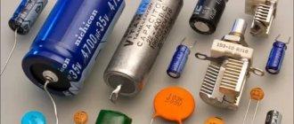
What is a capacitor
Condenser , or as people say - “conder”, is formed from the Latin “condensatus”, which means “compacted, condensed”.
It is a passive radio element that has the property of retaining an electric charge on its plates, if, of course, it is charged with some kind of power source beforehand. Roughly speaking, a capacitor can be thought of as a battery or accumulator of electrical energy. But the whole difference is that an accumulator or battery contains an EMF source, while a capacitor lacks this internal source.
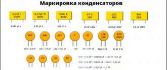
Capacitor markings
The marking of a capacitor, regardless of its type, contains two mandatory parameters - capacitance and rated voltage. The most common digital marking indicates the resistance value. It uses three or four digits.
Briefly, the essence of the three-digit marking: the first two digits on the left indicate the capacitance value in picofarads. The rightmost number shows how many zeros should be added to the numbers on the left. The result is obtained in picofarads. Example: 154 = 15x104 pF. On foreign-made capacitors, pF are designated as mmf.
In a four-digit code, the capacitance in picofarads is indicated by the first three digits, and the fourth indicates the number of zeros to be added. For example: 2353=235x103 pF.
To designate the capacity, alphanumeric markings containing the letter R can also be used, which indicates the location of the decimal point. For example, 0R8=0.8 pF.
On the case, the voltage value is indicated by a number followed by the letters: V, WV (which means “operating voltage”). If there is no indication of the permissible voltage, then the capacitor can only be used in low-voltage circuits.
In addition to capacitance and voltage, other characteristics of the part may be indicated on the case:
- Dielectric material. B – paper, C – mica, K – ceramics.
- Degree of protection from external influences. G – hermetically sealed design, O – pressed housing.
- Design. M – monolith, B – barrel, D – disk, C – sectional version.
- Current mode. I – pulsed, U – universal, CH – direct current only, P – alternating/direct.
What does a capacitor consist of?
Any capacitor consists of two or more metal plates that do not touch each other. For a more complete understanding of how all this works in a capacitor, let's imagine a pancake.
spread it with condensed milk
and put the exact same pancake on top
The condition must be met: these two pancakes must not touch each other. That is, the top pancake should lie on the condensed milk and not touch the bottom pancake. Here, I think, everything is clear. Here is a typical “pancake capacitor” :-). This is how all capacitors are designed, only thin metal plates are used instead of pancakes, and various dielectrics are used instead of condensed milk. The dielectric can be air, paper, electrolyte, mica, ceramics, and so on. Wiring is connected to each metal plate - these are the leads of the capacitor.
Schematically it all looks something like this.
As you may have noticed, due to the dielectric, the capacitor cannot conduct current. But this applies only to direct current. The capacitor passes alternating current through itself without problems with a small resistance, the value of which depends on the frequency of the current and the capacitance of the capacitor itself.
Where are capacitors used?
Capacitors are used in almost all modern devices: subwoofers, electric motors, cars, pumps, power tools, air conditioners, refrigerators, mobile phones, etc.
Depending on the functions performed, they are divided into general purpose and highly specialized.
General purpose capacitors include low-voltage storage devices that are used in most types of electrical equipment.
Highly specialized ones include high-voltage, pulse, noise suppression, dosimetric and start-up capacitors.
Capacitor capacity
Electric charges
As you know, there are two types of charges: positive charge and negative charge. Well, everything is as usual, like charges repel, and unlike charges attract. Physics seventh grade).
Let's look again at the simple capacitor model.
If we connect our capacitor to some DC power source, then we will charge . At this moment, the positive charges that come from the plus of the power source will settle on one plate, and the negative charges from the minus of the power source will settle on the other.
The most interesting thing is that the number of positive charges will be equal to the number of negative charges.
Even if we disconnect the DC power source, our capacitor will remain charged.
Why is this happening?
Firstly, the charge has nowhere to flow. Although over time it will still discharge. It depends on the dielectric material.
Secondly, there is an interaction of charges. Positive charges are attracted to negative ones, but they cannot connect with each other because they are interfered with by the dielectric, which, as you know, does not allow electric current to pass through. At this time, an electric field arises between the plates of the capacitor, which stores the energy of the capacitor.
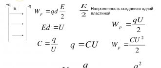
When a capacitor charges, the electric field between the plates becomes stronger. Accordingly, when the capacitor is discharged, the electric field weakens. But how much charge can we cram into a capacitor? This is where the concept of capacitor capacitance comes into play.
What is capacity
The capacitance of a capacitor is its ability to store charge on its plates in the form of an electric field.
But not only the capacitor can have capacitance. For example, the capacity of a bottle is 1 liter, or the capacity of a gas tank is 100 liters, and so on. We can’t cram a 1 liter capacity into a bottle larger than what this bottle is designed for, right? Otherwise, the remaining liquid simply will not fit into the bottle and will pour out of it. Exactly the same thing happens with a capacitor. We can't cram more charge into it if it's not designed to handle it. Therefore, the capacitance of the capacitor is expressed by the formula:
Where
C is the capacitance, Farad
Q is the amount of charge on one of the capacitor plates, Coulombs
U - voltage between plates, Volts
It turns out that 1 Farad is when a charge of 1 Coulomb is stored on the plates of the capacitor and the voltage between the plates is 1 Volt. Capacitance can only take positive values.
A value of 1 Farad is too high. In practice, the values of microfarads, nanofarads and picofarads are mainly used. I would like to remind you that the prefix “micro” is 10-6, “nano” is 10-9, pico is 10-12.
Where are capacitors used?
The operation of electronic, radio engineering and electrical devices is impossible without capacitors.
In electrical engineering they are used for phase shifting when starting asynchronous motors. Without a phase shift, a three-phase asynchronous motor in a single-phase alternating network does not function.
Capacitors with a capacity of several farads - ionistors - are used in electric vehicles as engine power sources.
To understand why a capacitor is needed, you need to know that 10-12% of measuring devices operate on the principle of changing electrical capacitance when environmental parameters change. The capacitance reaction of special devices is used for:
- recording weak movements through increasing or decreasing the distance between the plates;
- determining humidity by recording changes in dielectric resistance;
- measuring the level of liquid, which changes the capacity of the element when filled.
It is difficult to imagine how automation and relay protection are designed without capacitors. Some protection logics take into account the recharge rate of the device.
Capacitive elements are used in circuits of mobile communication devices, radio and television equipment. Capacitors are used in:
- high and low frequency amplifiers;
- power supplies;
- frequency filters;
- sound amplifiers;
- processors and other microcircuits.
It is easy to find the answer to the question of what a capacitor is needed for if you look at the electrical diagrams of electronic devices.
Flat capacitor and its capacity
A parallel plate capacitor is a capacitor that consists of two identical plates that are parallel to each other. The plates can be of different shapes. In practice, you can most often find square, rectangular and round plates. Let's look at a simple flat square capacitor.
flat capacitor
Where
d is the distance between the capacitor plates, m
S—area of the smallest plate, m2
ε is the dielectric constant of the dielectric between the plates of the capacitor
The finished formula for a flat capacitor will look like this:
Where
C is the capacitance of the capacitor, f
ε is the dielectric constant of the dielectric
ε0—dielectric constant, f/m
S—area of the smallest plate, m2
d—distance between plates, m
Yes, I know, the question immediately arises in your mind: “What is the dielectric constant ?” The dielectric constant is a constant value that is needed for calculations in some electromagnetism formulas. Its value is 8.854 × 10⁻¹² f/m.
Dielectric constant - this value depends on the type of dielectric that is located between the plates of the capacitor. For example, for air and vacuum this value is 1; for some other substances you can look at the table.
What conclusion can be drawn from this formula? If you want to make a capacitor with a huge capacity, make the area of the plates as large as possible, the distance between the plates as small as possible, and use distilled water instead of the dielectric.
Currently, capacitors are made from several plates in the form of a layer cake. It roughly looks like this.
multilayer capacitor
In this case, the formula of such a capacitor will take the form:
multilayer capacitor formula
where n is the number of plates
Electrical capacity
- Electrical capacity
characterizes the ability of conductors or a system of several conductors to accumulate electrical charges, and, consequently, electricity, which can later be used, for example, in photography (flash), etc.
- Back in the middle of the 18th century. It was believed that electricity is a special liquid contained in any charged body. If the charge of the body decreased, then this was explained by the “evaporation” of this liquid. To reduce “evaporation” (conservation of charge), it was proposed to place a charged body in some kind of container - an electrical capacitance
.
A distinction is made between the electrical capacity of a single conductor and a system of conductors (in particular, capacitors).
Electrical capacity of a solitary conductor
- A solitary
conductor is a conductor located far from other charged and uncharged bodies so that they do not have any influence on this conductor.
- The electrical capacity of a solitary conductor
is a physical quantity equal to the ratio of the electric charge of a solitary conductor to its potential:
\(~C = \dfrac{q}{\varphi}\) or \(~C = \dfrac{\Delta q}{\Delta \varphi}\).
The SI unit of electrical capacitance is the farad
(F).
- 1 F is the electrical capacity of a conductor whose potential changes by 1 V when a charge of 1 C is imparted to it.
Since 1 F is a very large unit of capacity, submultiple units are used:
1 pF (picofarad) = 10-12 F, 1 nF (nanofarad) = 10-9 F, 1 µF (microfarad) = 10-6 F, etc.
The electrical capacity of a conductor does not depend on the type of substance and charge, but depends on its shape and size, as well as on the presence of a dielectric nearby.
If the solitary conductor is a charged sphere, then the field potential on its surface
\(~\varphi = \dfrac{q}{4 \pi \cdot \varepsilon_0 \cdot \varepsilon \cdot R} = \dfrac{k \cdot q}{\varepsilon \cdot R}\),
where R
is the radius of the sphere, ε is the dielectric constant of the medium in which the conductor is located.
Then the electrical capacity of an isolated spherical conductor \(~C = \dfrac{q}{\varphi} = 4 \pi \cdot \varepsilon_0 \cdot \varepsilon \cdot R = \dfrac{\varepsilon \cdot R}{k}.\)
- The electrical capacity of a sphere the size of the Earth is only 709 microfarads. The electrical capacity of a sphere is equal to 1 F if the radius of the sphere is 1400 times greater than the radius of the Earth, i.e. R
= 9⋅1012 m.
Electrical capacity of two conductors
Usually in practice we deal with two or more conductors. Let us consider two conductors of arbitrary shape located in a homogeneous dielectric. Let's tell them the charges + q
and –
q
.
, a certain potential difference (voltage) will be established between the conductors: φ1 – φ2 = U.
The experiment shows that increasing the charge of each conductor, for example, by 2 times leads to an increase in the voltage between them also by 2 times, i.e. the ratio \(\dfrac{q}{U}\) for a given conductor pair remains constant:
\(\dfrac{q_1}{U_1} = \dfrac{q_2}{U_2} = \ldots = const = C.\)
- Electrical capacity of two conductors is a physical quantity equal to the ratio of the electric charge of one of the conductors to the potential difference (voltage) between them
\(~C = \dfrac{q}{\varphi_1 - \varphi_2} = \dfrac{q}{U}. \)
The electrical capacity of two conductors depends on the shape and size of the conductors, on their relative position and the relative dielectric constant of the filling medium space between them.
Maximum operating voltage on capacitor
All capacitors have some kind of maximum voltage that can be applied to them. The point is that a breakdown of the dielectric may occur and the capacitor will fail. Most often, this voltage is written on the capacitor body itself. For example, on an electrolytic capacitor.
maximum operating voltage of the capacitor
In technical documentation, this parameter is most often designated as WV, which means Working Voltage (operating voltage), or DC WV - Direct Current Working Voltage - constant operating voltage of the capacitor.
There is one nuance here that is often forgotten. The fact is that on the capacitor it is written exactly what direct voltage it is designed for, and not alternating. If a capacitor like the one in the picture above, with a maximum operating voltage of 50 Volts, is inserted into an AC circuit with a power supply that produces 50 Volts AC, your capacitor will explode. Because 50 Volts AC is effective voltage. Its maximum value will be 50 × √2 = 70.7 Volts, which is much more than 50 Volts.
Basic parameters of capacitors
Capacity
This indicator characterizes the capacitor's ability to accumulate electrical charge. The larger the area of the conductor plates and the smaller the thickness of the dielectric layer, the larger the capacitance. This characteristic also depends on the dielectric material. The device indicates the nominal capacity. The actual capacity, depending on operating conditions, may differ from the nominal capacity within significant limits. Standard options for nominal capacity range from units of picofarads to several thousand microfarads. Some models may have a capacity of several tens of farads.
Classic capacitors have a positive capacitance, that is, the greater the applied voltage, the greater the accumulated charge. But today, devices with unique properties, which scientists call “anti-capacitors,” are under development. They have negative capacitance, that is, as the voltage increases, their charge decreases, and vice versa. The introduction of such anti-capacitors into the electronics industry will speed up the operation of computers and reduce the risk of overheating.
What happens if you install a drive with a larger/smaller capacity than required? If we are talking about smoothing out voltage ripples in power supplies, then installing a capacitor with a capacitance exceeding the required value (within reasonable limits - up to 90% of the nominal value) in most cases improves the situation. Installing a capacitor with a smaller capacitance may degrade the performance of the circuit. In other cases, the possibility of installing a part with parameters different from the specified ones is determined specifically for each case.
Specific capacitance
The ratio of the nominal capacitance to the volume (or mass) of the dielectric. The thinner the dielectric layer, the higher the specific capacitance, but the lower its breakdown voltage.
Energy Density
This concept refers to electrolytic capacitors. The maximum density is typical for large capacitors, in which the mass of the housing is significantly lower than the mass of the plates and electrolyte.
Rated voltage
Its value is reflected on the housing and characterizes the voltage at which the capacitor operates during its service life with parameters fluctuating within specified limits. The operating voltage must not exceed the rated value. For many capacitors, the rated voltage decreases as the temperature increases.
Polarity
Polar capacitors are electrolytic capacitors that have positive and negative charges. On domestically produced devices, a “+” sign was usually placed at the positive electrode. On imported devices, a negative electrode is indicated, next to which there is a “-” sign. Such capacitors can perform their functions only if the voltage polarity is connected correctly. This fact is explained by the chemical features of the reaction of the electrolyte with the dielectric.
What happens if you reverse the polarity of a capacitor? Usually in this case the devices fail. This occurs due to the chemical destruction of the dielectric, which causes an increase in current strength, boiling of the electrolyte and, as a result, swelling of the housing and a possible explosion.
Most charge storage devices belong to the group of non-polar capacitors. These parts ensure correct operation no matter how the pins are connected to the circuit.
Capacitor leakage current
The point is that no matter what the dielectric is, the capacitor will still discharge sooner or later, since, oddly enough, current still flows through the dielectric. The magnitude of this current is also different for different capacitors. Electrolytic capacitors have the highest leakage current.
Also, the leakage current depends on the voltage between the capacitor plates. Ohm's law already works here: I=U/Rdielectric. Therefore, you should never apply a voltage greater than the maximum operating voltage specified in the datasheet or on the capacitor itself.
Parasitic parameters of capacitors
Capacitors, in addition to their main characteristics, have so-called “parasitic parameters” that distort the operating properties of the oscillating circuit. They must be taken into account when designing the circuit.
These parameters include their own resistance and inductance, which are divided into the following components:
- Electrical insulation resistance (r), which is determined by the formula: r = U/Iout, in which U is the power source voltage, Iout is the leakage current.
- Equivalent series resistance (ESR). This value depends on the electrical resistance of the material of the plates, leads, contacts between them, and losses in the dielectric layer. The ESR increases with increasing frequency of the current supplied to the storage device. In most cases, this characteristic is not important. The exception is electrolytic storage devices installed in the filters of switching power supplies.
- Equivalent series inductance - L. At low frequencies, this parameter, due to the self-inductance of the plates and leads, is not taken into account.
Parasitic parameters also include Vloss - an insignificant value expressed as a percentage, which shows how much the voltage drops immediately after the capacitor stops charging.
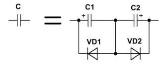
Non-polar capacitors
Non-polar capacitors include capacitors for which polarity is unimportant. Such capacitors are symmetrical. The designation of non-polar capacitors on electrical circuits looks like this.
capacitor designation in the diagram
Variable capacitors
These types of capacitors have an air dielectric and can change their capacitance under the influence of an external force, such as a human hand. Below in the photo are Soviet types of such variable capacitors.
variable capacitors
The modern ones look a little prettier
trimmer capacitors
A variable capacitor differs from a trimmer only in that the variable capacitor is turned more often than a trimmer. They turn the trimmer once in a lifetime)
In the diagrams they are designated as follows.
variable capacitor designation on the diagram
On the left is variable, on the right is tuning.
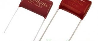
Film capacitors
Film capacitors are the most common of the large family of capacitors. They are named so because instead of a dielectric, a thin film is used here, which can consist of polyester, polypropylene, polycarbonate, Teflon and much more. Such capacitors range from a nominal value of 5 pF to 100 µF. They can be made according to the burger principle
And also according to the principle of roll
Let's look at the K73-9 Soviet film capacitor.
K73-9 Soviet capacitor
What's inside? Let's see.
As expected, a roll of foil with a dielectric film
what's inside a capacitor
Ceramic capacitors
Ceramic capacitors are capacitors that are made of ceramic or porcelain that are plated with silver. Take a square or round disk, spray silver on both sides, draw out the leads and voila! The capacitor is ready! That is, there is the simplest flat capacitor, which we talked about earlier in this article.
Would you like to get more capacity? No problem! Put the discs in a sandwich and increase the capacity
Ceramic capacitors may look like this:
ceramic capacitors
ceramic teardrop capacitors
SMD capacitors
SMD capacitors are ceramic capacitors that are built like a sandwich.
structure of SMD capacitor
They are used in microelectronics because they are tiny in size and easy to industrially produce using robots that automatically place SMD components on the board. You can easily find this type of capacitor on the boards of your mobile phones, on computer motherboards, as well as in modern gadgets.
Capacitor design
The designs of modern capacitors are varied, but several typical options can be distinguished:
Batch design
Used in glass-enamel, ceramic and glass-ceramic capacitors. The packages are formed by alternating layers of plates and dielectric. The covers can be made of foil, or they can be layers on dielectric plates - sprayed or applied by burning.
Each stack capacitor has upper and lower plates that have contacts at the ends of the stack. Terminals are made of wire or tape strips. The package is pressed, sealed, and covered with protective enamel.
Tubular design
High-frequency capacitors can have this design. They are a ceramic tube with a wall thickness of 0.25 mm. A silver conductive layer is applied to its outer and inner sides by burning in. The outside of the part is treated with an insulating substance. The inner lining is brought out onto the outer layer to attach a flexible lead to it.
Disc design
This design, like the tubular one, is used in the manufacture of high-frequency capacitors.
The dielectric in disk capacitors is a ceramic disk. Silver plates are burned onto it, to which flexible leads are connected.
Cast sectional construction
It is used in monolithic multilayer ceramic capacitors used in modern equipment, including integrated circuits. A part with 2 grooves is made by casting ceramics. The grooves are filled with silver paste, which is secured using the implantation method. Flexible leads are soldered to the silver inserts.
Roll design
Characteristic of paper film low-frequency capacitors with high capacity. Paper tape and metal foil are rolled into a roll. In metal-paper capacitors, a metal layer up to 1 micron thick is applied to the paper tape.
Polar capacitors
For polar capacitors, it is very important not to confuse the leads during installation. The positive leg should be connected to the plus in the diagram, and the negative leg to the minus. Polar capacitors are designated in the same way as their counterparts. The only difference is the indication of the polarity of such a capacitor. They may look like this on the diagrams.
designation of polar capacitors in the diagram
Electrolytic capacitors
Electrolytic capacitors are used in electronics and electrical engineering where large capacitance values are required. The name “electrolytes” also came into use.
electrolytic capacitors
The structure of electrolytic capacitors is very similar to film capacitors, which are also assembled according to the roll principle, but with only one difference. Instead of a dielectric, aluminum oxide is used here.
structure of an electrolytic capacitor
Let's take a look at one of these electrolytic capacitors for the sake of science.
We remove its body and see the same roll
We unwind the “roll” and see that between two layers of metal foil we have paper soaked in some kind of solution.
what's inside an electrolytic capacitor
Some people mistakenly believe that paper is the same dielectric, although this is completely wrong. How can it be a dielectric if it is soaked in a solution that conducts electric current?
In fact, the dielectric in this case is a thin layer of aluminum oxide, which is produced electrochemically in production. It all looks something like this:
diagram of the structure of an electrolytic capacitor
The aluminum oxide layer is so thin that it is possible to produce capacitors of enormous capacity with small dimensions. You haven't forgotten the capacitance formula for a flat-plate capacitor, have you?
where d is the same layer of aluminum oxide. The thinner it is, the greater the capacity.
On polar capacitors you can often see this arrow icon, which indicates the negative terminal of the capacitor.
designation of the negative terminal of an electrolytic capacitor
That is, in electrical circuits with direct current, you must strictly follow the rule: plus for plus, and minus for minus. If you mix it up, the capacitor may blow.
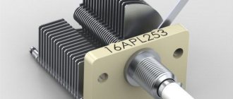
Tantalum capacitors
Tantalum capacitors are available in both wet and dry versions. Although, in dry form they are much more common. Here tantalum oxide is used as a dielectric. Tantalum oxide has better properties compared to aluminum oxide. If the biggest disadvantage of electrolytic capacitors is their high leakage current, then tantalum capacitors do not have this disadvantage. The disadvantage of tantalum capacitors is that they are designed for a lower voltage than their electrolytes. Tantalum capacitors are also polar, like electrolytic capacitors.
Tantalum capacitors may look like this
tantalum capacitors
or like this
drop tantalum capacitors
Ionistors
There is also a special class of capacitors - ionistors. Sometimes they are also called supercapacitors or gold capacitors. No, not because there is gold there. The very principle of operation of the ionistor is more valuable than gold. In order to obtain maximum capacity, we must spread the “condensed milk” (dielectric) with a thin, thin layer or increase the area of the pancakes (metal plates). Since it is very expensive to endlessly increase the layer of pancakes, the developers decided to reduce the dielectric layer. Since the dielectric layer between the plates of the ionistor, that is, the “condensed milk layer,” is 5-10 nanometers, therefore the capacitance of the ionistor reaches impressive values! Just imagine what kind of charge such a supercapacitor can accumulate!
The capacity of such capacitors can reach up to ten farads. Believe me, this is a lot. Capacitors look like regular tablets and can also look like cylindrical capacitors. In order to distinguish them from capacitors, just look at the capacitance that is indicated on them. If there are units of Farad, then this is definitely an ionistor!
ionistor large ionistor
Currently, ionistors have become very widely used in electronics and electrical engineering. They replace small batteries with low voltage, because the ionistor cannot yet be designed for a voltage of more than a few volts. But you can connect them in series and dial in the required voltage. But the pleasure is not cheap :-).
They also charge very quickly as their resistance is limited only by their leads. And based on Ohm’s law, the lower the resistance of the conductor, the greater the current flowing through it and, therefore, the faster the ionistor charges. The ionistors can be charged and discharged almost endlessly.
Types and types of capacitors
Capacitive elements are classified according to the type of dielectric used in the design.
Paper and metal-paper capacitors
The elements are used in circuits with constant or slightly pulsating voltage. The simplicity of the design results in a 10-25% decrease in the stability of characteristics and an increased amount of losses.
In paper capacitors, the aluminum foil plates are separated by paper. The assemblies are twisted and placed in a housing in the shape of a cylinder or rectangular parallelepiped.
The devices operate at temperatures -60...+125°C, with a rated voltage of up to 1600 V for low-voltage devices, above 1600 V for high-voltage devices and a capacity of up to tens of microfarads.
In metal-paper devices, instead of foil, a thin layer of metal is applied to dielectric paper. This helps to produce smaller elements. With minor breakdowns, self-healing of the dielectric is possible. Metal-paper elements are inferior to paper ones in terms of insulation resistance.
Electrolytic capacitors
The design of the products resembles paper ones. But in the manufacture of electrolytic cells, paper is impregnated with metal oxides.
In paperless electrolyte products, the oxide is applied to a metal electrode. Metal oxides have one-way conductivity, which makes the device polar.
In some models of electrolytic cells, the plates are made with grooves that increase the surface area of the electrode. Gaps in the space between the plates are eliminated by pouring electrolyte. This improves the capacitive properties of the product.
The large capacity of electrolytic devices—hundreds of microfarads—is used in filters to smooth out voltage ripples.
Aluminum electrolytic
In devices of this type, the anode plate is made of aluminum foil. The surface is coated with a metal oxide - a dielectric. The cathode plate is a solid or liquid electrolyte that is selected so that the oxide layer on the foil is restored during operation. Self-healing dielectric extends the operating time of the element.
Capacitors of this design require polarity. If you turn it back on, it will break the case.
Devices containing back-to-back polar assemblies are used in 2 directions. The capacity of aluminum electrolytic cells reaches several thousand microfarads.
Tantalum electrolytic
The anode electrode of such devices is made from a porous structure obtained by heating tantalum powder to +2000°C. The material looks like a sponge. Porosity increases surface area.
Using electrochemical oxidation, a layer of tantalum pentoxide up to 100 nanometers thick is applied to the anode. The solid dielectric is made from manganese dioxide. The finished structure is pressed into a compound - a special resin.
Tantalum products are used at current frequencies above 100 kHz. The capacitance is created up to hundreds of microfarads, with an operating voltage of up to 75 V.
Capacitor in DC circuit
So, we take a constant voltage power supply and set the voltage on its crocodiles to 12 Volts. We also take a 12 Volt light bulb. Now we insert a capacitor into the open circuit.
No, the light is not on.
But if you exclude the capacitor from the circuit and connect it directly to the light bulb, then the lamp lights up.
This suggests a conclusion: direct current does not flow through the capacitor! That is, in a direct current circuit, an ideal capacitor has an infinitely large resistance.
To be honest, at the very initial moment of applying voltage, the current still flows for a few seconds. It all depends on the capacitance of the capacitor.
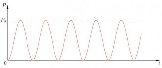
Operating principle of capacitors
When a circuit is connected to an electrical source, electrical current begins to flow through the capacitor. At the beginning of the passage of current through the capacitor, its strength is at its maximum and the voltage is at its minimum. As the device accumulates charge, the current drops until it disappears completely, and the voltage increases.
During the process of charge accumulation, electrons accumulate on one plate and positive ions on the other. Charge does not flow between the plates due to the presence of a dielectric. This is how the device accumulates charge. This phenomenon is called the accumulation of electric charges, and the capacitor is called an electric field accumulator.
Capacitor in AC circuit
In order to find out how a capacitor behaves in an alternating current circuit, we need to assemble a simple circuit, which is a voltage divider. The meaning of the experiment is this: using a frequency generator, we will change only the frequency, and leave the amplitude unchanged. Essentially, the red dot will show us the signal from the frequency generator, and the yellow dot will show us the signal on the resistor. By taking a signal from a resistor, we can indirectly find out how the capacitor behaves based on the laws of the voltage divider.
Designation of capacitors in the diagram
In the drawings, a capacitor with a constant capacitance is indicated by two parallel lines - plates. They are signed with the letter "C". Next to the letter they put the serial number of the element on the diagram and the capacitance value in pF or µF.
In variable capacitors, parallel lines are crossed out by a diagonal line with an arrow. Tuning models are indicated by two parallel lines crossed out by a diagonal line with a dash at the end. The designation of polar capacitors indicates a positively charged plate.
| Fixed capacitor |
| Polarized (polar) capacitor |
| Variable capacitor tuning capacitor |
| Varicap |
Capacitor resistance formula
Using physical and mathematical transformations, physicists and mathematicians have derived a formula for calculating the resistance of a capacitor. Please love and respect:
where XC is the resistance of the capacitor, Ohm
P is a constant and equals approximately 3.14
F - frequency, measured in Hertz
C - capacitance, measured in Farads
So, put the frequency in this formula at zero Hertz. A frequency of zero Hertz is direct current. What will happen? 1/0=infinity or very high resistance. In short, a broken circuit.
Capacitor Energy Formula
Closely related to capacitance is another quantity known as the energy of a charged capacitor. After charging any capacitor, a certain amount of energy is formed in it, which is subsequently released during the discharge process. The capacitor plates interact with this potential energy. They form opposite charges that attract each other.
Types of capacitors
Capacitors differ in a number of parameters: by configuration, by the type of dielectric, by the material of the plates, by the type of change in capacitance (constant, variable, interlinear), by operating voltage. Below in the figure we consider the main types of electrical devices of various configurations.
Flat
The flat type of the device consists of two plates that are located parallel to each other. They are compact while maintaining large capacity.
The capacitance of a parallel-plate capacitor increases as the area of the plates increases and the distance between them decreases.
To calculate the capacitance of a flat capacitor, you should use the formula C = ε0 εS / d
Spherical
A spherical capacitor consists of two concentrically located spheres with a thin dielectric between them. The outer surface of the outer plate is grounded to create an electric field directly between the plates. Taking into account the geometry of the plates, the capacitance of a spherical capacitor is calculated using the formula
C = 4πεε0 Rr/ R - r, where R is the radius of the outer lining, r is the radius of the inner.
Cylindrical
A cylindrical capacitor is made of two hollow cylinders with different radii of their forming circles with a common axis. There is a dielectric between the outer surface of the small cylinder and the inner surface of the large one. To calculate the capacitance of a cylindrical capacitor, you can use the formula C = 2πєє0L/ ln (R2/R1),
where L is the length of the cylindrical plates,
R2 is the radius of the outer cylinder,
R1 is the radius of the inner cylinder,
ln - designation of logarithmic action.
Series and parallel connection of capacitors
The most popular type of capacitor connection is parallel. With this connection, the electrical capacity increases, but the voltage remains original.
Several capacitors can be connected to one point.
Since the electrical capacitance of the capacitors is equal to the area of the plates, the total capacitance with this type of connection is proportional to the sum of the capacitances of all capacitors in the circuit.
Message = C1+C2.
When capacitors are connected in series, the total capacitance decreases and the operating voltage of the capacitor increases.
The capacitors are connected so that only the first and last have access to the emf/current source of one of their plates. The charge is the same on all plates, but the outer ones receive a charge from the source, and the inner ones are formed due to the separation of charges that previously neutralized each other. We can calculate the capacitance of a series connection of two capacitors using the formula
Message = C1*C2/ C1+C2.
How to charge and discharge a capacitor
To charge the drive, it is connected to a DC source. Charging stops when the power source voltage is equal to the voltage on the plates.
Discharging a capacitor may be necessary to safely disassemble household appliances and electronic devices. Electronic device storage devices are discharged using a conventional dielectric screwdriver. To discharge large storage devices that are installed in household appliances, it is necessary to assemble a special discharge device.
Capacitor design
Series connection of capacitors
A capacitor consists of two conducting electrodes (plates) separated by a dielectric layer. The thickness of the insulator is negligible compared to its linear dimensions. The capacitance increases in proportion to the area of the plates and in inverse proportion to the thickness of the dielectric.
In high-capacity elements, to reduce their dimensions, the “plating - dielectric - plating” structure is rolled up or made multilayer.
Capacitor design
How to choose a starting capacitor
For it to work most effectively, you need to choose the right container. To calculate it, various formulas are used, depending on the method of connecting the windings. The calculations are performed as follows:
- It is necessary to determine the operating current and voltage of the motor. When carrying out calculations, the designations I and U are used for them. The current value is taken from the operating instructions for the motor, and as U we take the one provided by the supply voltage.
- Capacity is determined by the formula C = (K x I) / U.
If the windings are connected in a triangle, K = 4800 is used, and when connected in a star, K = 2800 should be used. The result of the calculation is the capacitance expressed in microfarads.
Connecting a single-phase asynchronous motor Source sibay-rb.ru
When making calculations, the rated current must be taken into account. We are talking about the maximum permissible operating current under conditions when the engine is operating in normal mode. In practice, its value depends on the available load. If it is not there, then the value will be minimal.
This value is called no-load current. It is actually compensation for losses associated with energy losses in windings, dielectrics, friction and other similar reasons.
Connecting a three-phase motor to a single-phase network Source stroysvoy-dom.ru
If you gradually increase the load, the current will increase. Then it will reach the nominal value. With a subsequent increase, the current will continue to increase, but the speed will begin to fall. Prolonged stay in this mode will lead to increased wear of the equipment and possible breakdown.
You can determine the rated current not only from the operating instructions, but also measure it yourself. In the latter case, its value will be determined more accurately. This measurement can be done as follows:
- Disconnect the capacitors.
- Start the engine in operating mode.
- Using a current clamp, the current strength is determined.
Based on the obtained value, the required capacity is determined. Then they purchase the required part and install it. In this case, deviation from the calculated value is allowed by no more than 15%.
Schemes for connecting a three-phase motor to a single-phase network Source orenburgelectro.ru
When connecting a single-phase motor, the capacity of the working capacitor is determined as follows. You need to take 7 microfarads for every 100 watts of rated power. For starting, the capacity is chosen 2-3 times larger. Single-phase asynchronous motors are often used in home appliances.
For this purpose, capacitors of the following designs are usually chosen:
- metal-paper, high-frequency, which are designated MBGCH;
- heat-resistant paper type belonging to the BHT variety;
- paper in a sealed metal case - KBG-MN.
If the motor needs to rotate in the reverse direction, the connection to the capacitor will need to be changed. To do this, it will be enough to simply swap the terminals. If we are talking about replacing an existing part, then it is most convenient to choose it with the same characteristics as before.
As a working one, you must use a non-polar capacitor designed for use with alternating current. This is due to the fact that the polarity will constantly change during operation. However, it is permissible to use a polar one as a starter. In order to prevent the voltage sign from changing, it is necessary to connect this part via a diode.
Using starting and running capacitors for connection Source uk-parkovaya.ru
Magnitude and value of capacitor loss
Capacitor leakage current is a critical factor to use, especially when applied to power electronics. The loss is directly related to the properties of the dielectric.
No dielectric is capable of insulating metal plates with a 100% guarantee.
A current will always pass through the insulator, less or more depending on the properties of the dielectric and energy will be lost. In addition to the insulating properties of the dielectric, the following factors influence the leakage current:
- ambient temperature;
- shelf life of the capacitor without voltage, temperature;
- the magnitude of the leakage current is directly proportional to the voltage applied to the plates.
You can restore the functionality of a capacitor after long-term storage by applying operating voltage to it for several minutes.
At this stage, the oxidizing layer accumulates again and restores the functionality of the capacitor.
Story
The prototype of the first capacitor was the “Leyden jar,” invented in 1745. It was a glass jar in which the linings were thin sheets of tin foil glued to the inside and outside of the walls. The experimenter’s hands could act as the outer covering, and the liquid could serve as the inner covering.
Leyden jar
Note! The first electric shock from a capacitor discharge was obtained when testing a Leyden jar with palms instead of the outer lining.
Calculation formulas
Capacitance measurements are carried out using a specially derived formula. Electrical capacitance (C) is the ratio of the imparted charge (Q) to the resulting potential (U). The formula used to measure capacitance is: C=Q/V. The unit of measurement is the farad, which is denoted by the letter F. A capacitance of 1 farad will store a charge q = 1 coulomb with a voltage across the plates U = 1 Volt. Since capacitors have different types, the formulas are also different.
Through mathematical expressions
The mathematical expression for determining the capacitance of the capacitor C = q*U in SI units of each of the physical quantities included in the formula determines the value of 1 farad.
How does capacitance depend on the dielectric medium?
The effect of an insulator on the capacitance of a capacitor depends on the conductive properties of the substance inside that pad. The ability of an interplate conductor to insulate is called dielectric constant. Taking into account the characteristics of the dielectric, the formula for the capacitance of a flat device will become: C = є0є S/d, where under the letter є is the value of the dielectric constant of the insulator, and є0 is a constant value equal to the dielectric constant of vacuum (air).
In practice, a coefficient is used that indicates how many times the dielectric used reduces the electric field compared to air.
Table: