The quality of electricity supplied to our homes is not always satisfactory. We often say: “voltage drops”, “voltage jumps”, “voltage surges”, “bad voltage”. Let's understand these concepts together. It should be noted right away that precise determinations of deviations from power quality standards are very complex. In one article it is impossible to provide a complete description of the requirements for electrical parameters and methods for conducting official measurements. The texts of the relevant GOSTs and standards take up dozens of pages and contain numerous complex calculation formulas. In this article we will provide only a general understanding of the basic requirements for power quality and simple descriptions of common deviations
Main indicators of power quality
List of main indicators of electrical energy quality:
- steady voltage deviation;
- voltage change range;
- flicker dose;
- voltage waveform sinusoidal distortion factor;
- coefficient of the nth harmonic component of voltage;
- negative sequence voltage asymmetry coefficient;
- zero sequence voltage asymmetry coefficient;
- frequency deviation;
- duration of voltage dip;
- impulse voltage;
- temporary overvoltage factor.
Voltage deviation
One of the power quality is voltage deviation .
The voltage deviation is determined by the value of the steady-state voltage deviation. The following standards are established for the value of voltage deviation: normally permissible and maximum permissible values of steady-state voltage deviation at the terminals of electricity receivers are equal to +5 and +10%, respectively, of the rated voltage of the electrical network.
The voltage deviation value is determined when the process lasts more than one minute. Normally permissible deviation
voltage is considered to be a range of 5%, that is: +/-5% (from 209 V to 231 V).
The maximum permissible
voltage deviation is considered to be a range of 10%, that is: +/-10% (from 198 V to 242 V).
For the power quality indicators defined above, the following standards apply: positive and negative voltage deviations at the point of transmission of electrical energy should not exceed 10% of the nominal or agreed voltage value for 100% of the time of the one-week interval.
Electrical energy quality
Electrical energy as a commodity is used in all spheres of human activity, has a set of specific properties and is directly involved in the creation of other types of products, affecting their quality.
The concept of electrical energy quality (EQ) differs from the concept of quality of other types of products. Each electrical receiver is designed to operate under certain parameters of electrical energy: rated frequency, voltage, current, etc., therefore, for its normal operation the required CE must be provided. Thus, the quality of electrical energy is determined by the totality of its characteristics, under which electrical receivers (ER) can operate normally and perform their intended functions. CE at the point of production does not guarantee its quality at the point of consumption. The EC before and after turning on the electric power supply at the point of its connection to the electrical network may be different. CE is also characterized by the term “electromagnetic compatibility”. Electromagnetic compatibility is understood as the ability of an electronic device to function normally in its electromagnetic environment (in the electrical network to which it is connected), without creating unacceptable electromagnetic interference for other electronic devices operating in the same environment.
The problem of electromagnetic compatibility of industrial EDs with the power supply network has arisen acutely in connection with the widespread use of powerful valve converters, arc steel-smelting furnaces, and welding installations, which, despite all their economy and technological efficiency, have a negative impact on CE.
CE in industry is assessed according to technical and economic indicators, which take into account damage due to damage to materials and equipment, disruption of the technological process, deterioration in the quality of products, and a decrease in labor productivity - the so-called technological damage. In addition, there is electromagnetic damage from low-quality electricity, which is characterized by an increase in electricity losses, failure of electrical equipment, disruption of automation, telemechanics, communications, electronic equipment, etc.
CE is closely related to the reliability of power supply, since the normal mode of power supply to consumers is one in which consumers receive electricity uninterruptedly, in a quantity previously agreed upon with the energy supply organization, and of standardized quality. Article 542 of the Civil Code of the Russian Federation introduces the obligation to supply electricity, the quality of which meets the requirements of state standards and other mandatory rules or energy supply contracts.
In accordance with the Law of the Russian Federation “On the Protection of Consumer Rights” (Article 7) and the Decree of the Government of Russia dated August 13, 1997. No. 1013, electrical energy is subject to mandatory certification according to the electricity quality indicators established by GOST 13109-97 “Electric energy quality standards in general-purpose power supply systems.”
Electric energy quality indicators.
The requirements of GOST 13109-97 “Electric energy quality standards in general-purpose power supply systems” establish the following power quality indicators (PQE):
- steady voltage deviation;
- voltage change range;
- flicker dose;
- voltage waveform sinusoidal distortion factor;
- coefficient of the nth harmonic component of voltage;
- negative sequence voltage asymmetry coefficient;
- zero sequence voltage asymmetry coefficient;
- frequency deviation;
- duration of voltage dip;
- impulse voltage;
- temporary overvoltage factor.
When determining the values of some PKEs, the standard introduces the following auxiliary parameters of electrical energy:
- interval between voltage changes;
- voltage dip depth;
- frequency of voltage dips;
- pulse duration at a level of 0.5 of its amplitude;
- duration of temporary overvoltage.
Part of the PKE characterizes the steady-state operating modes of electrical equipment of the energy supply organization and consumers of electricity (EE) and gives a quantitative assessment by CE of the features of the technological process of production, transmission, distribution and consumption of EE.
Electrical energy quality indicators include:
- steady-state voltage deviation, voltage waveform sinusoidal distortion factor,
- coefficient of the nth harmonic component of voltage,
- negative sequence voltage asymmetry coefficient,
- zero sequence voltage asymmetry coefficient,
- frequency deviation, voltage change range.
All PCEs related to voltage are assessed based on their current values.
To characterize the above indicators, the standard establishes numerical normal and maximum permissible values of PKE or norms.
Another part of the PKE characterizes short-term interference that occurs in the electrical network as a result of switching processes, thunderstorm atmospheric phenomena, the operation of protective equipment and automation, and in post-emergency modes. These include voltage dips and pulses, short-term overvoltages. For these PKEs, the standard does not establish acceptable numerical values. To quantify these PCEs, the amplitude, duration, frequency of their occurrence and other characteristics established but not standardized by the standard must be measured. Statistical processing of this data makes it possible to calculate generalized indicators that characterize a specific electrical network in terms of the likelihood of short-term interference.
To assess the compliance of the PKE with the specified standards (with the exception of the duration of voltage dips, impulse voltage and temporary overvoltage coefficient), the standard establishes a minimum calculation period of 24 hours.
Due to the random nature of changes in electrical loads, the requirement to comply with CE standards during this entire time is practically unrealistic, therefore the standard establishes the probability of exceeding CE standards. The measured PCEs should not go beyond the normally permissible values with a probability of 0.95 for the calculated period of time established by the standard (this means that individual exceedances of standardized values can be ignored if their expected total duration is less than 5% over the established period of time).
The recommended total duration of PCE measurements should be selected taking into account the mandatory inclusion of workdays and weekends and is 7 days.
The standard identifies the likely culprits for the deterioration of CE. The frequency deviation is regulated by the power supply system and depends only on it. Individual electric power plants at industrial enterprises cannot influence this indicator, since their power is disproportionately small compared to the total power of power plant generators in the energy system. Voltage fluctuations, voltage asymmetry and non-sinusoidality are caused mainly by the operation of individual powerful electric power plants at industrial enterprises, and only the value of these electric power factor depends on the power of the supply power system at the consumer connection point in question. Voltage deviations depend both on the voltage level supplied by the power system to industrial enterprises, and on the operation of individual industrial electric power plants, especially those with high reactive power consumption. Therefore, CE issues should be considered in direct connection with issues of reactive power compensation.
The table shows the properties of electrical energy, the indicators that characterize them and the most likely culprits for the deterioration of CE.
&
| Properties of electrical energy | CE indicator | The most likely culprits for the deterioration of FE |
| Voltage deviation | Steady-state voltage deviation | Energy supply organization |
| Voltage fluctuations | Voltage range Flicker dose | Consumer with variable load |
| Non-sinusoidal voltage | Distortion factor of the sinusoidal voltage curve Coefficient of the nth harmonic component of the voltage; | Consumer with nonlinear load |
| Unbalance of three-phase voltage system | Negative sequence voltage asymmetry factor; Zero sequence voltage asymmetry factor; | Consumer with asymmetrical load |
| Frequency deviation | Frequency deviation | Energy supply organization |
| Voltage dip | Voltage dip duration | Energy supply organization |
| Voltage pulse | Pulse voltage | Energy supply organization |
| Temporary overvoltage | Temporary overvoltage factor | Energy supply organization |
7.2. Voltage deviation
Voltage deviations from nominal values occur due to daily, seasonal and technological changes in the electrical load of consumers; changes in the power of compensating devices; voltage regulation by generators of power plants and at substations of power systems; changes in the layout and parameters of electrical networks.
The voltage deviation is determined by the difference between the effective U and the nominal voltage values B:
or in %
The steady-state voltage deviation is equal in %:
where is the steady-state (effective) voltage value over the averaging interval.
In single-phase electrical networks, the effective value of voltage is defined as the value of the fundamental frequency voltage without taking into account the higher harmonic components of the voltage, and in three-phase electrical networks - as the effective value of the positive sequence voltage of the fundamental frequency
The standard normalizes voltage deviations at the terminals of electrical energy receivers. Normally permissible and maximum permissible values of steady-state voltage deviation are equal to ±5 and ±10%, respectively, of the rated voltage value and at points of general connection of electrical energy consumers must be established in energy supply contracts for the hours of minimum and maximum loads in the power system, taking into account the need to comply with the standards for terminals of electrical energy receivers in accordance with regulatory documents.
7.3. Voltage fluctuations
Voltage fluctuations are caused by a sharp change in the load on the section of the electrical network under consideration, for example, the inclusion of an asynchronous motor with a high frequency of starting current, technological installations with a rapidly variable operating mode, accompanied by shocks of active and reactive power - such as the drive of reversible rolling mills, arc steel-smelting furnaces, welding devices, etc.
Voltage fluctuations are characterized by two indicators:
- voltage change range;
- dose of flicker.
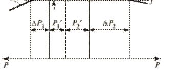
The range of voltage changes is calculated using the formula:
where , are the values of successive extrema (or extremum and horizontal section) of the envelope of the rms voltage values, in accordance with Fig. 1.
Fig.1. Voltage fluctuations
The repetition rate of voltage changes, (1/s, 1/min) is determined by the expression:
where m is the number of voltage changes during time T; T – measurement time interval, taken equal to 10 minutes.
If two voltage changes occur less than 30 ms apart, they are treated as one. The time interval between voltage changes is:
Assessment of the permissibility of voltage change ranges (voltage fluctuations) is carried out using curves of the dependence of permissible fluctuation ranges on the frequency of repetitions of voltage changes or the time interval between subsequent voltage changes. CE at the point of common connection with periodic voltage fluctuations having a meander (rectangular) shape (see Fig. 2) is considered to comply with the requirements of the standard if the measured value of the range of voltage changes does not exceed the values determined from the curves in Fig. 2 for the corresponding frequency of voltage changes, or the interval between voltage changes.
Fig.2. Voltage fluctuations of arbitrary shape (a) and meander-shaped (b)
The maximum permissible value of the sum of the steady-state voltage deviation and the range of voltage changes at points of connection to electrical networks with a voltage of 0.38 kV is equal to ±10% of the rated voltage.
Flicker dose is a measure of a person's susceptibility to the effects of fluctuations in luminous flux caused by voltage fluctuations in the supply network over a specified period of time.
The standard establishes short-term () and long-term doses of flicker () (short-term is determined over an observation time interval of 10 minutes, long-term over an interval of 2 hours). The initial data for the calculation are flicker levels measured using a flicker meter - a device that simulates the sensitivity curve (amplitude-frequency response) of the human visual organ. Currently, the development of flicker meters to monitor voltage fluctuations has begun in the Russian Federation.
EC for flicker dose meets the requirements of the standard if short-term and long-term flicker doses, determined by measurement over 24 hours or calculation, do not exceed the maximum permissible values: for a short-term flicker dose - 1.38 and for a long-term flicker dose - 1.0 (with a voltage baths with a shape different from a meander).
The maximum permissible value for a short-term flicker dose at points of common connection of electricity consumers with incandescent lamps in rooms where significant visual strain is required is 1.0, and for a long-term flicker dose - 0.74, with voltage fluctuations with a shape other than a meander.
7.4. Non-sinusoidal voltage
In the process of generating, converting, distributing and consuming electricity, distortions in the shape of sinusoidal currents and voltages occur. Sources of distortion are synchronous generators of power plants, power transformers operating at increased values of magnetic induction in the core (at increased voltage at their terminals), AC-to-DC converting devices and electric drives with nonlinear volt-ampere characteristics (or nonlinear loads).
Distortions created by synchronous generators and power transformers are small and do not have a significant impact on the power supply system and the operation of the electrical equipment. The main cause of distortion is valve converters, electric arc steel-smelting and ore-thermal furnaces, arc and resistance welding installations, frequency converters, induction furnaces, a number of electronic technical means (TV receivers, PCs), gas-discharge lamps, etc. Electronic electricity receivers and gas-discharge lamps are created at their own operation there is a low level of harmonic distortion at the output, but the total number of such EDs is large.
Non-sinusoidal voltage is characterized by the following indicators:
- Distortion factor of the sinusoidal voltage curve;
- The coefficient of the nth harmonic component of voltage.
The distortion factor of the sinusoidal voltage curve is determined by the expression:
where is the effective value of the nth harmonic component of the voltage, V; n is the order of the harmonic component of the voltage, N is the order of the last of the harmonic components of the voltage taken into account, the standard sets N = 40, is the effective value of the fundamental frequency voltage, V.
It is allowed to determine by the expression:
where is the rated network voltage, V.
The coefficient of the nth harmonic component of the voltage is equal to:
It is allowed to calculate using the expression:
To calculate, it is necessary to determine the voltage level of individual harmonics generated by the nonlinear load.
The harmonic phase voltage at the design point of the network is found from the expression:
where is the effective value of the phase current of the nth harmonic; – voltage of the nonlinear load (if the design point coincides with the point of connection of the nonlinear load, then = ); – rated network voltage; – short circuit power at the point of connection of the nonlinear load.
For the calculation, it is necessary to first determine the current of the corresponding harmonic, which depends not only on the electrical parameters, but also on the type of nonlinear load.
7.5 Frequency deviations
Frequency deviation – difference between actual and nominal frequency values, Hz
or:
The standard establishes normal and maximum permissible values of frequency deviation equal to ± 0.2 Hz and ± 0.4 Hz, respectively.
7.6. Voltage dip
Voltage dips include a sudden significant change in voltage at a point in the electrical network below the level of 0.9, followed by a restoration of the voltage to the original or close to it level after a period of time from ten milliseconds to several tens of seconds (Fig. 3).
Fig.3.
Voltage dip
A characteristic of a voltage dip is its duration - , equal to:
where and are the initial and final moments of the voltage dip.
The voltage dip is also characterized by the depth of the voltage dip - the difference between the nominal voltage value and the minimum effective voltage value, expressed in voltage units or as a percentage of its nominal value. The voltage dip is calculated using the following expressions:
or, %
The maximum permissible value of the duration of a voltage dip in electrical networks with voltages up to 20 kV inclusive is 30 s. The duration of an automatically eliminated voltage dip at any point of connection to electrical networks is determined by the time delays of relay protection and automation.
7.7. Voltage surge and temporary overvoltage
Distortion of the shape of the supply voltage curve can occur due to the appearance of high-frequency pulses during network switching, operation of arresters, etc. A voltage pulse is a sudden change in voltage at a point in an electrical network, followed by a restoration of the voltage to its original or close to it level. The magnitude of voltage distortion is characterized by the pulse voltage indicator (Fig. 4).
Fig.4. Pulse voltage parameters
The pulse voltage in relative units is equal to:
where is the value of the pulse voltage, V.
The pulse amplitude is the maximum instantaneous value of the voltage pulse. Pulse duration is the time interval between the initial moment of the voltage pulse and the moment the instantaneous voltage value is restored to the original or close to it level. Indicator - impulse voltage is not standardized by the standard.
Temporary overvoltage is an increase in voltage at a point in the electrical network above 1.1 for a duration of more than 10 ms, occurring in power supply systems during switching or short circuits (Fig. 5).
Fig.5. Temporary overvoltage
Temporary overvoltage is characterized by the temporary overvoltage coefficient(): this is a value equal to the ratio of the maximum value of the envelope of the amplitude voltage values during the existence of the temporary overvoltage to the amplitude of the nominal network voltage.
The duration of a temporary overvoltage is the time interval between the initial moment of occurrence of a temporary overvoltage and the moment of its disappearance.
The temporary overvoltage factor is also not standardized by the standard.
The values of the temporary overvoltage coefficient at the connection points of the general purpose electrical network, depending on the duration of the temporary overvoltage, do not exceed the values given in the table:
Dependence of the temporary overvoltage coefficient on the duration of the overvoltage
| Duration of temporary overvoltages, s | Up to 1 | Up to 20 | Up to 60 |
| Temporary overvoltage factor, p.u. | 1,47 | 1,31 | 1,15 |
On average, about 30 temporary overvoltages are possible at the connection point per year.
7.8. Influence of higher harmonics
The development of modern semiconductor technologies is leading to an ever-increasing number of consumers controlled by thyristors and converters. Unfortunately, converters increase the value of inductive reactive power and worsen the non-sinusoidal shape of the current curve. This interference from the power supply network leads to damage and erroneous switching on of equipment and devices.
A typical converter current is a superposition of various sinusoidal current components, i.e. the main network frequency and a certain number of so-called higher harmonics (in a three-phase network, primarily harmonics of the 5th, 7th and 11th orders).
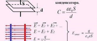
The content of higher harmonics in a three-phase network leads to an increase in the current in the capacitors, because The reactance of capacitors decreases with increasing frequency. Contamination of AC networks with higher harmonics can lead to the following consequences:
- reduced service life of capacitors;
- premature operation of protective equipment;
- failure or erroneous operation of computers, motor drives, lighting devices and other sensitive consumers.
In parallel with the increase in the current in the capacitors, which can be controlled by design measures, in unfavorable cases resonance phenomena can occur in the networks. The compensation capacitors and inductances of the transformer and network constitute a resonant circuit. If the natural frequency of such a circuit coincides with the frequency of higher harmonics, then oscillations with significant overcurrents and overvoltages may occur. This leads to overloads and damage in electrical installations.
The purpose of connecting a choke (reactor) to a capacitor is to reduce the resonant frequency of the network to a value lower than the value of the smallest higher harmonic of a given network. This prevents resonance between the capacitors and the network, and hence an increase in higher harmonic currents. In addition, such a connection has a filter effect, which reduces the degree of voltage distortion.
It is recommended in cases where the share of consumers polluting the network with higher harmonics is more than 20% of all network consumers to install a higher harmonic filter. For higher harmonic currents, the filter circuit represents a very low impedance. Therefore, most of these currents are directed to this circuit. The resonant frequency of a capacitor connected in series with the inductor always lies below the frequency of the 5th harmonic.
7.9. Main tasks and types of power quality control
The main objectives of FE control are:
- Verification of compliance with the requirements of the standard in terms of operational control of PKE in general-purpose electrical networks;
- Checking the compliance of the actual PCE values at the network interface according to the balance sheet with the values recorded in the energy supply contract;
- Development of technical conditions for consumer connection in terms of energy supply;
- Checking the fulfillment of contractual terms in terms of CE with the determination of the permissible calculated and actual contributions of the consumer to the deterioration of CE;
- Development of technical and organizational measures to ensure CE;
- Determination of discounts (surcharges) to tariffs for energy efficiency for its quality;
- Electrical energy certification;
- Search for the “culprit” of PCE distortions.
Depending on the goals solved when monitoring and analyzing CE, PCE measurements can take four forms:
- diagnostic control;
- inspection control;
- operational control;
- commercial accounting.
Diagnostic control of CE - the main goal of diagnostic control at the interface between the electrical networks of the consumer and the energy supply organization is to detect the “culprit” of the deterioration of CE, determine the acceptable contribution to the violation of the standard requirements for each PKE, include them in the energy supply contract, normalize the CE.
Diagnostic control should be carried out when issuing and checking the fulfillment of technical conditions for connecting a consumer to the electrical network, when monitoring contractual terms for power supply, as well as in cases where it is necessary to determine the share contribution to the deterioration of the energy efficiency of a group of consumers connected to a common power center. Diagnostic monitoring should be periodic and include short-term (no more than one week) PCE measurements. During diagnostic control, both standardized and non-standardized PCEs are measured, as well as currents and their harmonic and symmetrical components and the corresponding power flows.
If the results of diagnostic monitoring of the energy efficiency confirm the consumer’s “guilty” of violating the energy efficiency standards, then the main task of the energy supply organization together with the consumer is to develop and evaluate the possibilities and timing of measures to normalize the energy efficiency. For the period before the implementation of these measures, operational control and commercial metering of energy efficiency must be applied at the interface between the electrical networks of the consumer and the energy supplying organization.
At the next stages of diagnostic measurements of CE, the control points should be the buses of regional substations to which the cable lines of consumers are connected. These points are also of interest for monitoring the correct operation of on-load tap-changer devices of transformers, for collecting statistics and recording voltage dips and temporary overvoltages in the electrical network. This controls the operation of existing means of providing CE: synchronous compensators, banks of static capacitors and transformers with on-load tap-changers that provide specified ranges of voltage deviations, as well as the operation of protection and automation equipment in the electrical network.
CE inspection control is carried out by certification bodies to obtain information about the state of certified electricity in the electrical networks of the energy supplying organization, on compliance with the conditions and rules of application of the certificate, in order to confirm that the CE continues to meet the established requirements during the validity period of the certificate.
Operational monitoring of FE is necessary in operating conditions at points of the electrical network where voltage distortions exist and cannot be eliminated in the near future. Operational control is necessary at the connection points of traction substations of railway and urban electrified transport, substations of enterprises with electrical equipment with nonlinear characteristics. The results of operational control should be sent via communication channels to control centers of the electrical network of the energy supplying organization and the power supply system of an industrial enterprise.
Commercial metering of PC E - should be carried out at the interface between the electrical networks of the consumer and the energy supply organization and, based on its results, discounts (surcharges) on electricity tariffs for its quality are determined.
The legal and methodological basis for ensuring commercial accounting of energy costs in electrical networks is the Civil Code of the Russian Federation (Civil Code of the Russian Federation), part 2, GOST 13109 - 97, Instructions on the procedure for payments for electrical and thermal energy (No. 449 dated December 28, 1993 Ministry of Justice of the Russian Federation).
Commercial metering of energy efficiency must be continuously carried out at points of metering of consumed electricity as a means of economic influence on the culprit of energy efficiency deterioration. For these purposes, devices should be used that combine the functions of electricity metering and measuring its quality. The presence in one device of the functions of electricity metering and PKE control will make it possible to combine operational control and commercial accounting of KE, while common communication channels and means for processing, displaying and documenting ASKUE information can be used.
Commercial metering devices for energy efficiency must record the relative time of exceeding the normal and maximum permissible values of energy efficiency at the electricity control point for the billing period, which determine the tariff surcharges for those responsible for the deterioration of energy efficiency.
Voltage fluctuation
One of the power quality parameters is voltage fluctuation.
Voltage fluctuations are characterized by the following indicators:
- voltage change range;
- dose of flicker.
The voltage fluctuation values have the same standards as the voltage deviation with the only difference: the process duration is less than one minute. Normally permissible fluctuation
voltage is considered to be a range of 5%, that is: +/-5% (from 209 V to 231 V).
The maximum permissible
voltage fluctuation is considered to be a range of 10%, that is: +/-10% (from 198 V to 242 V).
Comment:
Do not confuse the GOST requirements for the quality of electricity in the network (GOST R 54149-2010 “Electric energy. Electromagnetic compatibility of technical equipment”) and GOSTs describing the quality of power supply for electrical appliances (for example, GOST R 52161.2.17-2009 “Safety of household and similar electrical appliances"). GOST power quality essentially imposes requirements on the supplier of electrical energy, and it is this GOST that you can rely on if you need to make demands on the supplier in case of poor power supply. And the requirements for the quality of power supply in the passports of devices determine the requirement for devices to operate normally in a wider range of current parameter values. For devices, as a rule, a voltage range is set from -15% to +10% of the nominal one.
Measurements of electrical energy quality indicators at the electrical energy transmission point
Legal entities and individuals, individual entrepreneurs.
There is no charge.
Technological connection to the electric networks of the network organization in the prescribed manner of power receiving devices and (or) electric power facilities of the consumer, an agreement concluded with Rosseti Center for the provision of services for the transmission of electrical energy or an energy supply agreement with the guaranteeing supplier (energy sales organization), the consumer’s application for checking the quality of electrical energy at the transmission point.
No more than 60 days, subject to an interim response being sent to the consumer within 30 working days, indicating the relevant reasons
Checking the compliance of the quality of electricity at the transmission point with the established requirements of GOST, drawing up a protocol for measuring the quality indicators of electrical energy.
Stage 1. Application from the consumer to carry out measurements of electrical energy quality indicators
- Condition of the stage
Technological connection to the Rosseti Center networks in the prescribed manner of the applicant’s power receiving devices - Contents
Submission by the consumer of an application indicating the details of the Applicant, location of energy receiving devices, measurement points, proposed date and time of measurements - Form of submission
In-person application by the applicant to the consumer service office, written application in a manner that allows confirmation of receipt - Execution period
Unlimited - Link to the regulatory legal act
Unified standards for the quality of service provided by grid organizations to consumers of services of grid organizations, approved by Order of the Ministry of Energy of Russia dated April 15, 2014 No. 186
Stage 2. Review of the application and agreement with the consumer on the points and timing of measurements of electrical energy quality indicators
- Stage condition:
Availability of all necessary information in the application - Contents
Coordination between Rosseti Center and the consumer of points and timing of measurements of electrical energy quality indicators - Submission form
By telephone, written request by registered mail with notification - Execution time
30 working days - Link to the regulatory legal act
Unified standards for the quality of service provided by grid organizations to consumers of services of grid organizations, approved by Order of the Ministry of Energy of Russia dated April 15, 2014 No. 186
Stage 3. Carrying out measurements of electrical energy quality indicators, processing and analysis of the results
- Condition of the stage
Points and timing of measurements of electrical energy quality indicators agreed with the consumer - Contents
Measurements of electrical energy quality indicators, processing and analysis of results - Submission form
In person - Execution time
In accordance with GOST 33073-2014, but not less than 7 working days - Link to the normative legal act
GOST 33073-2014 GOST 32144-2013
Stage 4. Registration and sending to the consumer the results of measurements of power quality indicators
- Condition of the stage
Generated database of measurement results of power quality indicators - Contents
Drawing up a protocol for measuring electrical energy quality indicators and sending it to the consumer - Form of provision
Written by registered mail with notification, in person in the office service - Completion period
No more than 60 days, subject to an interim response being sent to the consumer within 30 working days indicating the relevant reasons - Link to the regulatory legal act
GOST 33073-2014, Unified standards for the quality of service provided by network organizations to consumers of services of network organizations, approved by Order of the Ministry of Energy of Russia dated April 15, 2014 No. 186
GOST 33073-2014 “Electric energy. Electromagnetic compatibility of technical equipment. Control and monitoring of the quality of electrical energy in general purpose power supply systems"
GOST 32144-2013 “Electric energy. Electromagnetic compatibility of technical equipment. Standards for the quality of electrical energy in general purpose power supply systems"
1. The recommended form for submitting a written application is Appendix No. 19 to the MI.
2. Feeding methods:
- in writing to Rosseti Center or its branch, electrical network district (RES). The addresses are indicated on the official website of the Company in the “Contacts” section (https://www.mrsk-1.ru/ru/contact/common/);
- in electronic form on the official website of Rosseti (https://www.mrsk-1.ru/ru/clients/reception/);
- orally at consumer service centers and points. Addresses of consumer service centers and points on the official website of the Company in the “Consumers” section (https://www.mrsk-1.ru/ru/clients/customer-service/centers/);
- by calling the “power engineering direct line” 8 800-50-50-115 or 13-50.
Contact Center number: 13-50, 8 800-50-50-115
Rosseti Center email address
Voltage dip
One of the power quality parameters is voltage dip. The voltage dip is determined by the voltage dip time indicator.
Limit value
The duration of a voltage dip in electrical networks with voltages up to 20,000 V inclusive is 30 seconds. The duration of an automatically eliminated voltage dip at any point of connection to electrical networks is determined by the time delays of the relay protection and the response time of the automation.
A voltage dip is determined when the voltage drops to a value of 0.9U and is characterized by the duration of the process. The maximum permissible duration is 30 seconds. The depth of the failure can sometimes reach 100%.
Electromagnetic compatibility of electrical equipment
Electromagnetic compatibility of electrical equipment and electrical networks is understood as the ability of electrical energy consumers to function normally and not introduce unacceptable distortions into the electrical network that impede the work of other consumers.
If we talk about electrical compatibility in the broadest sense, then this should include all material manifestations and ideal consequences associated with charged particles and electromagnetic fields.
In a narrower sense, electromagnetic compatibility is understood as a set of electric, magnetic and electromagnetic fields that generate electrical objects created by man and which affect dead (physical) and living (biological) nature, technical, informational, social reality.
The latter, in particular, includes bioelectromagnetic compatibility, which consists in the emergence of zones of increased danger due to the conditions of electrostatic and electromagnetic influence.
For technical devices, the deterioration of the electromagnetic environment can become so severe that their functioning may be disrupted, the quality of electricity may deteriorate, and damage to relay protection and automation devices may occur.
The concept of quality of electrical energy differs from the concept of quality of other goods. The quality of electricity is manifested through the quality of operation of each electrical receiver. Therefore, if it works unsatisfactorily, and in each specific case an analysis of the quality of electricity consumed gives compliance with GOST, then the quality of manufacturing or operation is to blame.
If the PKE do not meet the requirements of GOST, then claims are made against the supplier - the energy company.
In general, PCEs determine the degree of voltage distortion in the electrical network due to conducted interference (distributed across the elements of the electrical network) introduced by both the energy supply organization and consumers.
1.2. Frequency deviation and reasons for its occurrence
Frequency deviation in the electrical system, Hz, characterizes the difference between the actual and nominal values of the frequency of alternating current in the power supply system and is determined by the expression
δf = f - fnom (1)
Permissible standards for frequency deviation are
δfnorm = ± 0.2 Hz, δflim = ± 0.4 Hz
The frequency of alternating current in an electrical system is determined by the rotation speed of power plant generators. The nominal frequency value in the Unified Energy System of Russia of 50 Hz in the electrical system can be ensured provided that there is an active power reserve. At each moment of time in the electrical system, equality (balance) must be ensured between the power of power plant generators and the power consumed by the load, taking into account power losses for transmission in the electrical network. Input of reserve power is possible in the system due to the additional energy consumption of power plant turbines.
How to improve power quality
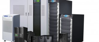
In case of significant deviations in power quality parameters, you should first contact the service organization, the electricity supplier. If administrative actions to improve the quality of electricity do not produce results, then it is necessary to use special means of protection. To improve power quality parameters, we recommend using: surge protection, voltage stabilizers, uninterruptible power supplies.
How to check and measure the quality of electrical energy?
Before proceeding with measurements that determine the quality of the electrical network, it should be taken into account that the PKE must be recorded by representatives of the electricity supplier. Based on the results of the inspection, a report is drawn up, on the basis of which a claim can be made.
To check all characteristics of electricity for compliance with the requirements of GOST 53144-2013, GOST R 54149-2010 and other regulatory documents, special measuring equipment will be required. But some of the main indicators can be measured using a conventional multimeter or the discrepancy can be determined by indirect signs.
1.3. Voltage deviation
Voltage deviation is characterized by an indicator of the steady-state deviation of the current voltage value C/ from the nominal value C/nom:
(2)
The voltage deviation is caused by changes in voltage losses (see Chapter 12) caused by changes in load power. The voltage deviation is normalized at the terminals of electrical energy receivers:
(3)
Types of protection against unpredictable changes in network parameters
Devices for protection against voltage surges
The energy supply company must take care of the proper quality of the services supplied, which comply with established regulations. But at the same time, each homeowner can personally protect their household appliances from power surges with special types of equipment:
- Uninterruptible power sources are capable of maintaining the operating condition of certain types of household appliances for a given time. For example, connecting such a device to a computer allows it to shut down correctly and save all the required files.
- Equipment designed to protect against voltage surges. The operating principle is similar to that of a relay. If one of the parameters of the electrical circuit reaches critical levels, the room is automatically de-energized.
- The voltage stabilizer controls that the voltage does not go beyond the specified parameters. Provides adequate power quality, but provided that deviations do not exceed 35%.
It is recommended to purchase equipment designed to protect household appliances in specialized stores. The electrical device must be accompanied by accompanying documentation and a warranty card.
Procedure for estimating parameters
It is impossible to carry out full power quality control without the use of complex, high-precision instruments. Licensed ones use equipment that combines the functions of a meter and analyzer. The properties of the transmitted current are constantly changing - only periodic power quality monitoring will allow problems to be identified and eliminated in a timely manner. LABSIZ specialists are sufficiently qualified and have permission to carry out measurements and assess the condition of electrical networks.
The approximate time frame for monitoring electricity parameters is once every 6–24 months, depending on the conditions of use.
What to do if the supplied energy does not meet the standards
The power quality system used by LABSIZ protects the user from overpaying for low-quality goods, equipment burnout, and short circuits. In the event of an accident allegedly caused by the supplier, you must:
- Call an independent expert to conduct an examination of the affected circuit and devices.
- Obtain an inspection report confirming the inadequate quality of electricity.
- Draw up a statement of claim against the supplier, attaching to it an act issued and certified by LABSIZ.
- Go to court for damages.
In the future, it makes sense to change the supplier of low-quality energy, and if this is not possible, regularly check the supplied energy to eliminate new losses and accidents.
What affects the characteristics of the power supply network
The quality of electricity is influenced by a fairly large list of factors:
- regular voltage drops as a result of connecting large loads;
- icing of supply lines;
- increased air humidity;
- the quality of electrical lines, the end of their operational period, their failure;
- At sea stations, ebb and flow tides are taken into account.
When it comes to wind farms, the quality of electricity can be adversely affected by changes in the direction and strength of wind flows.