First, something about powers
The school physics textbook says that there are four types of interactions (i.e. forces) - gravitational, electromagnetic, strong and weak. And it gives some comparison of them - in terms of range, magnitude of force and area of application. Let us note right away that it is possible to compare forces by radius of action only if this radius is uniquely defined, but in general it is better to say “depending on distance.” Further, if we already said about the dependence on distance, then we can say something about the dependence on time, i.e. about the speed of spread. The textbook is very simplistic about the speed of propagation of one of these four interactions, but at least it says something; if it talks about the other speed, it is only presumably, and about two more they are generally silent (although sometimes the authors mention the time of interaction). The fact that these interactions actually extend over such small distances that time does not matter is not an excuse. The logic must be followed, it must be mentioned. And finally, it’s strange to compare forces of different natures - they depend on different parameters (and also differently on distance).
Question 1.
What can be said about the speed of propagation of all interactions?
Since we have four types of interactions, we can expect that everything covered in the textbook is tied to these interactions. Gravitational interaction manifests itself in the movement of planets and satellites; textbooks do not consider more serious problems, although they tell you something about Lagrange points
,
the rotation curve of galaxies
,
the three-body problem
,
gravitational maneuver
and
the stability of the Solar system
would be quite possible. And this - partly as a solution, and partly as a statement of the problem - would be quite useful for understanding the picture of the world and the application of physics. Electromagnetic interaction manifests itself in the textbook in charge and field, then in current and induction, the third and last time in the electromagnetic field, i.e. in light and radio. The other two interactions remain at the word level. The question arises: what about the rest of the educational world - friction, support reaction, elasticity, properties of solids, liquids and gases?
We have to admit that this is all electromagnetism, but the textbook sometimes says something about this, sometimes is silent. And when it becomes completely unbearable, i.e. When it comes to batteries, the concepts of “external forces” and “chemical energy” are introduced. So - all this is electromagnetism, but build on the basis of the laws of electromagnetism a complete and consistent theory of friction, elasticity, strength, etc. modern physics can only partially. And in those segments in which this is possible, the theory turns out to be so complex that it is impossible to present it in a university textbook - and especially in a school one. Therefore, people resort to intermediate models, the parameters of which (friction coefficient, elasticity, strength, etc.) are determined experimentally, and then they try to relate these parameters to each other, moving towards the desired understanding of the structure of our world. Sometimes this can be done at a high-quality level at school.
Question 2.
Which coefficient of friction is greater: a hard material on a hard material or the same hard material on a soft one? What does the dependence of dielectric constant on frequency look like for a non-polar liquid (for example, liquid argon) and a polar liquid (for example, water)?
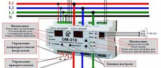
Operating principle
Each marking of current sources determines the principle of its operation. In a standard situation, energy is generated through the interaction of component parts, namely:
- Mechanical type. As a result of the interaction of mechanism parts, friction occurs. Due to this phenomenon, static electricity arises and is converted into current.
- Mechanical structures work by producing sequentially moving charged particles. The phenomenon occurs due to the interaction of a chemical element with an electrolyte. Charged particles leave the structure of the metal crystal lattice, becoming part of the conducting liquid.
- Solar batteries (light sources) work by knocking out charged particles from a dielectric (silicon) base under the influence of a light flux. This creates constant tension.
- Thermal. As a rule, these are 2 metal bases connected in series. One part heats up, while the other remains cooled. When the temperature regime changes, a temperature difference occurs, resulting in the movement of charged particles.
You may be interested in this Features of semiconductors
Important! Any change in the structure of a substance can lead to irreversible consequences that will manifest themselves during the operation of the device.
Equivalent circuit - what is it?
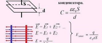
Now let's resort to an intermediate model and introduce the concept of internal resistance
source of electricity.
Let's connect our source to a variable resistance, measure the dependence of the output voltage and current in the load on the resistance and plot a graph of the dependence of voltage on current (Fig. 1). This dependence is called load characteristic
or
current-voltage characteristic
.
In many cases (for example, for galvanic sources - batteries and accumulators) it is close to straight line. And if so, then the idea arises - to represent the source with an equivalent circuit
from an ideal source of EMF and resistance. An equivalent circuit is a circuit made up of elements that are ideal in some sense and behaves in approximately the same way as a real device.
Rice. 1
Why have equivalent circuits become widespread? The reason for this is "coincidental": people created computers late. The fact is that the computer can be provided with information about the components of the circuit in any form, and a program can be written that - if this information is complete and consistent - will calculate the circuit. But if the dependencies that characterize the elements, for example, current-voltage characteristics, are nonlinear, then the amount of calculations turns out to be too large for manual calculations. That is why the concept of equivalent circuits once arose.
At the dawn of the physics of electricity, when people knew at least something about how water flows, and electricity was completely new, the “hydrodynamic analogy” was used to consider electricity when teaching - the flow of current was considered as the flow of water. Over time, the situation was inverted - electrical circuits, also in some sense equivalent, began to be used to describe hydrodynamics. To broaden your horizons, you can ask on the Internet for equivalent diagrams of hydraulic systems
or
equivalent circuits of electric motors
.
Now let's return to the load characteristic, make a few comments and ask questions. Remark one - the extreme points are called open-circuit voltage and short-circuit current, their connection with the parameters of the equivalent circuit is obvious - it can be seen in the figure. Remark two - the concept of internal resistance was created to describe the load characteristic, and it corresponds precisely to the linear model. If we want to use it extensively and calculate it for different sections of the real characteristic, then it will turn out to be somewhat different for them.
Question 3.
If the current-voltage characteristic is convex downward at low currents, and upward at high currents, as in Figure 1, then at what currents will the internal resistance be greater and at which will it be less? And also, is it possible to use the concept of internal resistance to determine the heat dissipation inside an electricity source?
Note three - you probably noticed that the term "electricity source" is used here. Only once did the “EMF source” flash, and this was not accidental. At school, you alternately use the expressions “EMF source” and “current source.” In physics, or more precisely in its engineering-physics branch, which is called TOE - Theoretical Fundamentals of Electrical Engineering (some students winced), these two terms mean some idealized sources of electricity. Namely, an “EMF source” is one that always has the same voltage at its output terminals (this is what was meant above, where it was mentioned the only time). And a “current source” is one through whose terminals and through the external circuit the same current always flows.
Question 4:
Explain why this is not always possible. Think about the conditions under which such a model works, and come up with a model of a real source using not an EMF source (as above), but a current source.
Now let's try to go beyond the ends of the load line. It’s not for nothing that we called it a straight line and not a segment (this is, of course, a joke). But first, one more, purely school question: how do the power of the source, the power in the load and the efficiency change along our straight line - which is still a segment? If we use a model with an EMF source, as in Figure 1, then the power created by the source increases with the current from P
= 0 to
P
= \( \mathscr{E} \)
I
= \( \mathscr{E}^2 \)/
r
.
The power in the load passes through a maximum at load resistance R
=
r
, and the power released in the source grows as
rI
2, i.e. all the way - don’t burn the source! Well, the efficiency accordingly drops from 100% to 0. With a matched load it is 50%. All these answers can be given without calculations, just by looking at the diagram and thinking a little.
And now - “above the barriers”! What will happen to the load characteristic if the current is greater than the short circuit current or flows in the opposite direction? You all (well, almost all) do it, some of you do it daily. Of course, in order to pass current through the load in the opposite direction, you need another voltage source, and not just any one. Which one? And how to enable it? And in order to pass through the load a current greater than the short-circuit current, an additional source is also needed, and here it must be turned on differently, and there will be not one, but two requirements for it. The current in the opposite direction is just a charging mode. Why batteries are charging, but the batteries are either not at all or very bad, read on the Internet, the key word is depolarizer
. So, in order for the current to flow through the load in the opposite direction, we include in the load a source with a greater EMF than that of the main source, and in the opposite direction. And in order for a current to flow greater than the short circuit current, we include in the load a source with a higher EMF than the main one, and such that \( (\mathscr{E}_1 + \mathscr{E}_2)/(r_1 + r_2) > \mathscr{E}_1/r_1\).
Nuclear power plants
Nuclear power plants operate using atomic (nuclear) energy. The efficiency of a nuclear power plant is approximately equal to that of a thermal power plant – 35%. Nuclear fuel is used as fuel - uranium, plutonium. When burning 1 kg of uranium, the same amount of heat can be extracted as from 3000 tons of coal.
Disadvantages include the problem of burying nuclear waste, as well as the release of radionuclides into the environment, which have a mutagenic effect on humans and all living beings and cause radiation sickness. The potential danger of radiation contamination during accidents poses a threat to life for many years.
Based on the foregoing, the following conclusions can be drawn, namely:
- Negative impact of most power plants on the environment.
- Inefficient use of non-renewable natural resources.
- Potential danger to the environment.
Based on all this, we can conclude that it is necessary to modernize existing power plants or introduce and search for new alternative types of energy sources. This requires significant financial expenditure.
About the battery design
It's time to ask what the parameters \( \mathscr{E} \) and r
.
When we lower a conductor (particularly a metal) into an electrolyte, ions from the metal begin to move into the solution and back. These fluxes depend, in particular, on the strength of the conductor lattice, the concentration of ions in the solution and temperature. When the ions pass, the electrode charges and a potential difference arises between the electrode and the solution, forming an electric double layer
.
As a result, such a potential difference is established so that the flows become equal and a dynamic equilibrium arises. If you lower another conductor into the same electrolyte, it will have its own potential relative to the electrolyte, which differs from the one that appeared on the first electrode. Thus, a potential difference arose between the electrodes, we invented the galvanic cell
.
backup voltaic cells online
. By the way, you even know from your school textbook that there are cells with two different electrolytes, separated by a semi-permeable membrane; so this is a highly simplified picture.
As for the internal resistance, it is connected, as usual, with the resistance of the medium through which the current is forced to flow. This is an electrolyte, i.e. what is between the electrodes (and the leads, but their resistance is usually negligible). However, since the load characteristic is not linear, then the resistance is not constant, but itself depends on the current. Moreover, if we uttered the words “electric double layer,” it means that we recognized that the medium is inhomogeneous. Internal resistance, as it should be (remember R
= ρ
L
/
S
?) actually decreases with decreasing thickness and increasing layer area. But it also decreases with increasing electrode roughness, and this indicates a large contribution to the resistance of the near-cathode layer, that same double layer. In general, you will have a field for research - and this area of physics is very, very in demand by technology.
Chemical sources of electrical energy create a potential difference at their terminals, and, accordingly, an electric field appears around them. In electrostatics, these things are inseparable - a charge has a field, lines of force (with all the conventions of this concept) end and begin at the charges. Outside of electrostatics, this may not be the case - if a circuit is pierced by an alternating magnetic flux, then an electric field arises in the circuit, its lines of force are closed, they do not begin and do not end at charges. Of course, such a field is not potential - by launching a charge into this circuit or simply placing a closed conductor in it, we will extract energy from it.
Question 5.
Where, by the way, will it come from?
Let the source of electricity have a potential difference between the terminals \( \mathscr{E} \) at I
= 0, i.e.
in the absence of consumption, in idle mode. Will there be a charge at the terminals? Sometimes they clarify - excess charge, so as not to hear that “there are always some charges - protons and electrons in atoms.” Naturally, the terminals will be charged with a charge Q
E
} \)
C
, where
C
is the capacitance between the terminals, proportional to the size of the terminals
D. When we connect the terminals with resistance R
, current will flow through it and through them.
If the current is not infinitely small, then the voltage between the terminals will decrease: U
< \( \mathscr{E} \), and the charge will also decrease.
The charge difference will be discharged through this same resistance in the form of a pulse current, the duration of this pulse will be of the order of τ = max( RC
,
D
/
c
), where
c
is the speed of light,
R
is the resistance of the terminals and load, it does not include the source resistance
r
.
In other words, the exchange of charges between the terminals will occur even if we break the source circuit, i.e. Let's make r
indefinitely large.
It would seem like an exotic situation? Yes, but absolutely real, for example - the Oxford electric bell
.
If we greatly simplify the situation, then this is a pendulum, the ball at the end of the thread oscillates, alternately touching the contacts of a high-voltage battery and, at the moment of contact, being charged from them. At the same time, the internal resistance of the battery is enormous, the average current consumption is negligible (the device runs on one battery for more than a century), but the charging time is very short, so the current in the pulse is significant. If the battery resistance is high, the charge of the ball touching the terminals occurs not with the “battery” current, but with the current of the charge accumulated at the terminals. Here is an estimate of the parameters: \( \mathscr{E} \) = 103 V, C
= 10−12 F,
Q
= 10−9 C, τ = 3 10−11 s,
Imax
=
Q
/τ = 30 A, however the average current is equal to the ratio
of Q
to the oscillation period
T
= 1 s, i.e. 10−9 A.
Purpose and application of the thermogenerator
Devices of this type have been known since the middle of the last century. They allow you to convert thermal energy into electrical energy. A modern version of an industrially produced thermogenerator is designed for installation on gas boilers or long-burning wood stoves with a power of at least 200 W.
One of the most famous and popular thermogenerator options in everyday life works in tandem with a kerosene lamp:
Image gallery
Photo from
Thermal generator on a kerosene lamp
Using the energy of burning kerosene
Heat to electricity converter
Ease of use and connection
Such a device allows you to receive about 150 kW/h of electricity per month in winter, when heating devices operate continuously.
You can consider it as an additional option in combination with solar panels or as a way to compensate for frequent power outages.
There are also camping models of heat generators that can process the thermal energy of a regular fire. They can be used during construction where there is no electricity as an alternative to a generator running on liquefied fuel.
Unusual sources
However, not all sources of electrical energy have a load characteristic similar to the direct one; there are also completely different situations. In particular, sources of electrical energy that use energy released during radioactive decay behave differently. A decaying atom is itself a converter of energy types, i.e. It converts intranuclear energy into mechanical energy, more precisely into kinetic energy, of decay products plus potential, if they are charged, plus electromagnetic, if they are quanta. Then there are several conversion options, one of them is through heat. Particles are decelerated in the medium, the energy is converted into heat (some of it into the destruction of interatomic bonds), and then there are many different ways, the most common is through thermoelectricity ( RTG
), others are possible. General reviews of these methods are available on the Internet.
Let's consider non-thermal ways of converting the energy of radioactive decay into electricity. Let's take two plates from a conductor, apply a radioactive isotope to one of them, place these plates in a vacuum, drawing conclusions from them. In some situations, the voltage between the terminals will begin to increase. Will it grow quickly and what size will it reach? It will grow only if, during decay, charged particles (α or β) fly out and land on the second plate. The growth rate is proportional to the number of decays per unit time, the particle charge and inversely proportional to the capacity: U
=
Q/C
, and Δ
U
/Δ
t
= Δ
Q
/(
C
Δ
t
) =
I
/
C
, where
I
is the current of these particles.
U
increase until something stops this current or a leakage current occurs in the shell, or a vacuum breakdown or breakdown through the air occurs.
But if everything is designed correctly, then there will be no leaks or breakdowns, and the voltage between the electrodes will gradually increase to such a point that charged particles simply stop reaching the second electrode. This will happen precisely when the voltage multiplied by their charge equals their original energy (Fig. 2; here the solid line is an idealization, the dashed line is closer to reality, e
is the charge, \( \mathscr{E} \) - energy,
Imax
is the current of charged particles).
Now we can figure out what the load curve will be for a nuclear battery of exactly this design - we stipulate this because real nuclear batteries are designed differently, and then we will tell you exactly how. But for now, here is this fundamental design proposed by Henry Moseley more than 100 years ago. “Five photographs of Henry Moseley”
on the Internet and read it.) And the load curve will be absolutely fantastic - just a horizontal straight line from zero current to maximum, when all charged particles have exactly the same energy and fly where they need to go, and drops to zero when the critical value of the braking voltage is reached. Because a current greater than the current of charged decay products cannot be obtained from an atomic battery of the simplest design.
Rice. 2
In reality, the energies of the particles differ slightly, if only because not all decaying atoms lie on the surface; some charged particles have to make their way to the surface and some of the energy remains on the plate - the source of the particles. In addition, not all charged particles fly perpendicular to the surfaces of the electrodes, and in order to prevent a particle emitted at an angle from crossing the gap, a smaller decelerating field is needed. Therefore, the real dependence will become less categorical.
However, this is only the beginning of the biography of nuclear batteries.
or, as they are also called,
isotope batteries
. All electrical equipment used by people uses a very specific range of voltages and currents. You will rarely see voltages higher than 20-30 kV, because at these voltages serious insulation problems arise, and if these are vacuum devices and the electrons in them have high energy, X-rays also occur. In other words, if you need to use all this, there are electronic devices with a voltage of 300 kV or more, and there are power lines of 500 kV or more - but this is industry, not everyday life, although very important for civilization, but narrow areas. As for the current, especially high currents are also not very convenient - the cross-section of the wires increases. So if a certain application requires a certain power, then the combinations of voltage and current can be different, this is determined by economics, circuit capabilities, tradition, etc. But in general, the combination of voltage and current that atomic batteries of a trivial design could provide is categorically inconvenient. It would be nice to have the voltage about three to four times less, and the current, correspondingly, more.
Several ways to solve this problem have been proposed, and it is important to understand two fundamental things. The better we use the high energy with which particles fly out, the higher the efficiency will be. Another limitation is that a small-sized device cannot have high voltage at the output terminals, otherwise a breakdown will occur. A small-sized device with high efficiency must somehow use the high energy of the particles inside itself, converting it into something. Let's see what options are offered.
The first is that charged particles enter the semiconductor film, where they are slowed down and give up their energy to electrons. This in itself would simply increase the conductivity, so the film is not homogeneous, it is p–n
- a transition with two, as it should be, conclusions.
Fast primary electrons decelerated in the p–n One electron with an energy of kiloelectronvolts generates thousands of pairs, each with a thousand times less energy, but there are a thousand times more of them - this will ensure an increase in current. True, when current is taken, electrons have to make their way through the semiconductor layer, and the current-voltage characteristic takes on the features of that of batteries - when current is taken, the voltage drops noticeably.
There are several problems with this design, and one is common to all nuclear batteries. Namely, the choice of isotope and its quantity. Half-life is the rate at which power decays over time and the life of the battery; the amount of isotope and the energy of the decay products is the power of the battery, its danger to others, and if it flies in space, then these are the consequences of arriving on Earth with destruction in the atmosphere and contamination (there have already been precedents) and its danger to surrounding devices. For example, semiconductor devices do not like to be irradiated. Naturally, there are also general technical problems - weight, dimensions, cost, service life, reliability, sometimes maintainability, patent clearance. Patent purity is important if you are going to produce and legally sell devices. Weight and dimensions - if it is wearable, transportable, on-board equipment of an aircraft. The most interesting thing is the service life and reliability, because sometimes a service life of 10,000 hours with a reliability of 0.9 is better, and sometimes 5,000 and 0.95 or 1,000 and 0.99 are better... (think about when and why).
Rice.
3 Another problem, which can also be called general technical, is the fundamental design, optimization of parameters, choice of materials and sizes. For example, in this case, you need to choose the optimal thickness of the layer containing the isotope so that the particles do not slow down in it. And choose the optimal semiconductor so that, for example, it is not destroyed by radiation. These issues are being researched and discussions can be easily found in the literature. According to the situation today, tritium T (aka 3H) and nickel-63 (aka 63Ni) are used as isotopes, silicon Si, silicon carbide SiC, gallium nitride and arsenide GaN and GaAs or diamond C are used as semiconductors. Figure 3 shows the current-voltage characteristic of an optimized source based on nickel and diamond.
Question 6.
Do you think this battery will heat up during operation, at what point in the characteristics will the battery deliver maximum power to the load and at what point will the heating be minimal.
Such a device may not have two electrodes - with and without an isotope; the isotope can simply contact the semiconductor. In this case, high-energy particles do not need to cross the vacuum gap - having been born, they immediately begin to propagate through the semiconductor, decelerating and generating numerous electron-hole pairs. Such batteries (Fig. 4) are already mass-produced, their voltage is 0.75–2.4 V, current 0.05–0.3 μA, service life 20 years. The decaying isotope is tritium T, so after 12 years the current drops by half, the semiconductor is silicon Si.
Rice. 4
Moreover, it is possible, at least theoretically, to look for an option when the isotope is one of the elements included in the semiconductor. For example, if you use the isotope carbon-14 (aka 14C), you can try diamond C or silicon carbide SiC as a semiconductor. Such ideas have been proposed, and since the half-life here is 5,700 years, the battery turns out to be eternal. But this parameter is for almost all applications (except for flight to extrasolar planets
) will be redundant, and the power will be relatively small. By the way, under certain conditions, graphene also becomes a semiconductor - so there is something to dream about.
Rice. 5
This option was also proposed - high-energy particles excite luminescence, this effect is known and used. For example, there are key fobs with tritium and phosphor (Fig. 5). The light is then converted into electricity by a photocell. But each conversion generally reduces the efficiency, and for photocells it is not very high.
There are known design options (some actually used, some at the level of the first laboratory samples) with the flight of charged particles through a vacuum, and the “arrival plane” is made flexible. In this case, when charged particles hit it, it bends, and if it eventually touches the “plane of departure,” the charge is thrown back. As a result, we get a generator not of constant, but of alternating voltage - which can also be useful for something. A periodically bending console can be used as a mechanical engine, and if the console itself is made of piezoelectric
- then as another source of tension, such an idea was proposed. In all cases, the considerations stated above remain in force - either high voltage, but then significant dimensions, or small dimensions, but then low efficiency. In the latter case, it becomes even smaller due to the presence of the second transformation.
Piezo crystal is another source of electricity. More precisely, a converter of work into electrical energy and vice versa, i.e. electricity to move. The resistance of a piezocrystal is very high, so its power as a converter of mechanical work into electrical power is low. It is usually used either as a source of high voltage and low power, for example in lighters, or as a displacement sensor - where power is not so important. In the opposite direction - as a way to create small movements. These are ultrasound generators and devices for precise movement of objects in microscopy and optics. A separate area of application is the use of mechanical resonance in a crystal.
The fundamental difference between the current-voltage characteristics of atomic batteries and conventional chemical ones is that atomic batteries carry charged particles and this flow is limited in principle. It can be stopped by applying the appropriate voltage to the terminals, but it is impossible to change its direction or pass through a nuclear battery a current greater than the short circuit current (unless, of course, we apply a voltage greater than the vacuum breakdown voltage - but at the same time we will remove the battery out of service).
Operating conditions of current sources
Any current source operates under certain conditions. In the absence of a chemical reaction, charged particles cannot form within the elements. If there is no anode and cathode, then particle movement will not occur even in the presence of a reaction.
A similar process occurs in batteries, but the impetus for the occurrence of a chemical reaction is a short circuit in the external electrical circuit. Charged elements begin to move from the anode to the cathode and vice versa, creating a constant flow.
Ideal and real
Light types cannot work without a light source. The efficiency depends on the type of dielectric element used. Additionally, it is necessary to have a device available for converting the received energy.
The thermal option will not work if it is based on 1 type of metal. If there is no source of heat, then the emergence of moving particles is out of the question.
Sources
To generate electrical energy, you need to select a current source that meets the needs of your specific application. There are several options for such devices, each of which has a specific structure, operating principle and individual technical indicators.
Main components of the electrical network
An electric power network (Fig. 5) is a set of electrical installations for the transmission and distribution of electrical energy, consisting of substations, switchgears, conductors, overhead and cable power lines operating in a certain territory.
Figure 5 - Electrical network and electrical installations for transmission and distribution of electrical energy
All circuits encountered in practice are combinations of individual elements - feeders, mains and branches.
Electrical networks, in turn, are divided into main electrical networks and distribution electrical networks.
Trunk networks include all high-voltage power lines (PTLs), distribution networks include power lines with a capacity below 110 kV. Types of electrical networks are presented in Figure 6.
Figure 6 - Types of electrical networks
The networks are interconnected by transformer and distribution substations. To meet the established requirements, power systems are equipped with special control centers equipped with monitoring, control, communication means and special layouts of power plants, transmission lines and step-down substations.
Electrical networks are divided into:
- tension;
- degrees of mobility;
- purpose;
- type of current and number of wires;
- electrical connection diagram:
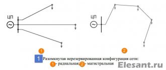
a) open (non-redundant). A diagram of open-loop networks is shown in Figure 7.
Figure 7 - Schemes of open-loop networks : a - radial (load only at the end of the line); b - main (the load is connected to the line in different places)
b) closed (redundant) (Fig. 8).
Figure 8 — Schemes of closed networks: a — network with two-way power supply; b - ring network; c - double main line; g complex network (for supplying critical consumers in two or more directions)
Main power supply circuits are used in the following cases:
- a) when the load is concentrated in nature, but its individual nodes are located in the same direction in relation to the substation and at relatively small distances from each other, and the absolute values of the loads of individual nodes are insufficient for the rational use of the radial scheme;
- b) when the load is distributed with varying degrees of uniformity.
By design: electrical wiring (power and lighting), current conductors - for transmitting electricity in large quantities over short distances, overhead lines - for transmitting electricity over long distances, cable lines - for transmitting electricity over long distances in cases where the construction of overhead lines is impossible.
The most widespread for local distribution networks are radial, main, mixed (radial-main) and loop schemes.
With a radial power supply scheme, each line is like a beam connecting a network node (substation, distribution point) with a single consumer.
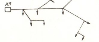
In the main power supply scheme, one line - the main line - serves, as indicated, several distribution points or receivers connected to it at its various points.
Mixed schemes of local distribution networks are used at different locations of consumers relative to the CPU and combine the principles of constructing both radial and main circuits.
The following requirements are imposed on electrical networks: reliability, survivability and efficiency.
Reliability is the main technical requirement, which refers to the ability of a network to fulfill its purpose within a given time and operating conditions, providing electrical receivers with electricity in the required quantity and proper quality.
The survivability of an electrical network is the ability to fulfill its purpose under conditions of destructive influences, including in a combat situation when exposed to enemy weapons.
Cost-effectiveness is the minimum cost of constructing and operating a network, subject to the requirements of reliability and survivability.