Electrical energy distribution networks - purpose
Electrical energy distribution systems or distribution networks are designed to
- Delivery of electrical energy with voltage from 6 kV to 10 kV to the consumer.
- Distribution of electrical energy across substations 380 V -35 kV.
- Capacity collection of heating and hydraulic substations with capacities up to hundreds of megawatts.
It is worth noting that in modern conditions, with a constant increase in electricity consumption, it has become conventional to divide electric power transmission and distribution networks by voltage into system-forming ones, transmission systems (extended) and power distribution systems. If previously only networks with voltages up to 35 kV were classified as distribution systems, today individual networks of 110 and even 220 kV can be included in this classification.
That is why, today, electrical energy distribution systems include
- Electrical networks with voltages from 6 to 150 kV, sometimes up to 220 kV.
- Two or three voltage levels after transformation: MV networks - medium voltage 110-150 kV, which are powered by HV (high voltage) networks 330-750 kV. Low voltage (LV) networks from 6 to 35 kV, which are powered from MV networks through MV/LV transformer substations or directly. Through the transformation of VN\NN.
- The lowest voltage level of distribution networks are networks with a voltage of 220-660 V, obtained with additional transformation of 6-35 kV\220-66 kV.
AC current
Most power plants are built using an alternating current generator. In addition, the amplitude voltage of alternating current is easily changed using transformers, so you can lower or increase the voltage level over a wide range. Most consumers of electrical energy are also focused on using alternating current. The use of three-phase alternating current is the world standard in the generation, transmission and conversion of electricity.
When consumers are combined by phase into groups from three-phase alternating current, single-phase alternating current is obtained, which is used by many household consumers. Each group of consumers is allocated one of three phases, while the second wire (“zero”), which is used when transmitting single-phase current, is common to all groups and is grounded at its starting point.
Distribution network configuration
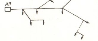
According to the configuration, distribution networks can be:
- Open (radial and main);
- Closed.
From the diagram we see that the radial circuit is longer and the implementation of the radial circuit requires more conductors, switching equipment, supports, insulators, etc. equipment. As a result, the radial RS circuit is more expensive than the main circuit. But according to the same scheme, we see that if any intermediate section of the backbone network fails, the following sections of the network will be de-energized, which indicates its lower reliability.
Note: In fact, in practice, combined distribution network designs are used, called backup distribution networks.
Cable selection and RCD use
To ensure the safety of electrical networks, RCD fire-fighting devices are installed in buildings and certain values are set on the device. In a residential building, the leakage current for common lines is set to 100 mA. Individual lines have a minimum value of 10 mA. When the indicator increases, the residual current device (RCD) de-energizes the building.
Electrical wiring is carried out using safe cables approved by GOST. Aluminum wire is not used for the internal electrical network. It is used to supply electricity to the house. The most preferred option for internal wiring is copper cable. Its advantages include:
- high current density;
- fracture toughness and good wear resistance;
- has little resistance to oxidation;
- Compared to aluminum, it does not compress, so there are no gaps in the joints.
The budget option includes the VVG brand. There are also other types with different properties:
| Cable brand | Purpose |
| Incombustible | Reduced gas and smoke emissions. |
| VVGng with three cores of 6 mm2 each. | For cable ducts in residential buildings. |
| VVGng (3x2.5) | For hidden box on sockets and distribution boxes. |
| VVGng (3x1.5) | Connected to lighting fixtures and switches. |
| PV1 | For electrical panel. |
| PVS (3x2.5) | For electrical appliances. |
For internal stationary wiring, single-core copper wire is most often used, since it is more reliable and durable than its multi-core counterpart.
Cables for internal electrical network
Source: https://yato-tools.ru
Redundant distribution networks
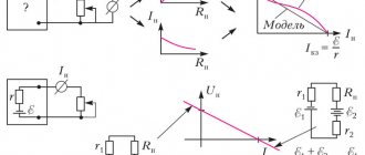
To create a reliable power supply system, medium voltage (MV) distribution networks are made according to backup schemes, simultaneously using both radial and main circuits.
In the figures we see implementations, a radial-backbone diagram of a backup distribution network (Figure 1.3) and a ring closed network diagram with a single power center.
In the next photo we see single and double network configurations with two-way power supply.
And this is a distribution network diagram made in a complex closed configuration with two power supplies (CPU).
Note: CPU is a substation. It receives electrical energy, reduces the high voltage of the distribution network through transformation (step-down substations) and distributes electrical energy to consumers. It is worth noting that there are also step-up substations.
Why apply standards?
To avoid dangers when installing electrical networks, correctly calculate the cross-sectional area of the wire, which is responsible for the resistance. The higher it is, the more the cable heats up. Proper selection plays an important role:
- cable material;
- wire connections;
- selection of installation location;
- insulating material.
It is important to correctly calculate the load, select protective devices and install grounding.
If you do not apply the standards established by law, errors will lead to a short circuit and a fire. If the rules are not followed, the insurance company will not pay insurance in the event of an accident.
Low voltage (LV) distribution networks
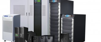
Low voltage (LV) distribution networks with a voltage of 380-10000 Volts are the most widespread. Within one network enterprise there may be hundreds of transformer substations and points. This is why such networks use inexpensive transformers without automatic voltage regulation.
©Elesant.ru
Other articles in the section: Electrical networks
- Automatic circuit breakers
- Types of power transmission line supports by material
- Types of supports by purpose
- Overhead power lines with SIP wires
- Wooden supports for overhead power lines
- Reinforced concrete power transmission line supports
- Reinforced concrete power transmission line supports
- Protection of humans from electric shock, direct and indirect contact
- How does a 380 Volt low voltage consumer receive electricity?
- Cable network wells installation stages
Electrical network structure
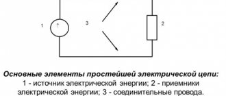
The network may have a complex structure, which is determined by the territorial location of sources, consumers, reliability requirements and other considerations. To connect substations in the network, there are power lines, which can be double (double-circuit) or single. They may also have taps (branches). As a rule, several lines approach substations. In the substations themselves, voltage conversion is carried out, as well as the distribution of electrical energy flows among suitable lines. To connect lines to equipment inside substations, various types of electrical switches are used. The structure of the power grid can change dynamically by switching switches.
To visually represent the structure of the network, a special outline of the electrical circuit diagram is used. These diagrams show lines, bus systems and sections, transformers, switches, and protection devices.
back to section “Directory of building materials (E)” back to section “Directory of building materials and terms”
Selecting a laying method
The choice of method for laying the electrical network is influenced by:
- place;
- environmental conditions;
- building size;
- wire section;
- network diagram.
Environmental influence:
- destroys the insulation of electrical equipment;
- poses a danger to operating personnel;
- provokes explosions and fires.
The insulation of wires, live parts and structures is destroyed by moisture, gases, caustic vapors and elevated temperatures. Because of this, a short circuit may occur, and a dangerous impurity may form in the air, leading to explosions and fires.
The location of the electrical line affects the installation method, safety, ease of work and operation.
Rules for introducing electricity into a building
Most often, electricity is introduced into a building using a self-supporting SIP wire. Additional poles to support the cable are not required if the power line support is located at a distance of up to 25 meters.
The wire is pulled to the electrical panel, in which the RCD, circuit breakers are located and the ground loops are connected. The transition to the VVGng cable is carried out in another panel with a metering device.
When entering, comply with the following requirements:
- If the wire length is more than 25 meters, then additional support is installed. To do this, a shield is installed on the nearest pole, and a ground loop is buried in the ground. The wire between the supports is stretched at a height of at least two meters above the ground.
- If cables cross building structures, they are installed in protective pipes.
- The minimum permissible distance from the ground to the building connection point is 2.75 meters.
- If the wire is pulled underground, it must first be placed in a protective sheath. Then they will place it in a ditch, the depth of which should be at least 0.7 meters.
The underground installation of the input is provided at the time of construction of the building and the energy supply project is prepared. Technical documentation is drawn up according to the rules. Therefore, drawings should be developed by specialists with experience in this field.
It is necessary to correctly determine the brand of cable and calculate the cross-section of the current-carrying wires. To sign an energy supply project, certain technical conditions are met, including obtaining permission to carry out excavation work, which is approved by the services responsible for:
- communication and power transmission systems;
- buildings and constructions;
- gas pipeline;
- heating mains;
- green spaces;
- water pipes;
- roads;
- sewer pipes.
If communications are located near the proposed cable laying site, then contact the responsible organizations to coordinate the location of the trenches and to control the work being carried out.
For underground installation, armored cables are used. It is forbidden to lay them in metal pipes along their entire length, since when filled with groundwater in the winter, the resulting ice will damage the wires.
Input of electricity into the building
Source: https://muchenergy.ru/