Electrical power is measured by a wattmeter . The wattmeter consists of a current coil connected in series with the load and another potential coil connected in parallel with the load.
Measuring power in a three-phase system (pictured: traditional power meter)
Depending on the strength of each movement of the magnetic field, the pointer acts on it. True or actual power is directly displayed in the wattmeter. In three-phase systems, power can be measured in several ways. One wattmeter can be used for time measurements.
However, for continuous measurements, a three-phase wattmeter with two elements is used, which shows both balanced and unbalanced loads.
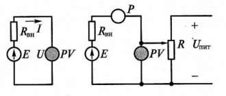
For an unbalanced load, two wattmeters must be used, as shown in Figure 1 .
The total power is calculated by adding the measurement readings given by two wattmeters. The power factor can also be obtained using this method.
When using the two-wattmeter , it is important to note that the reading of one wattmeter should be canceled if the system power factor is less than 0.5 . In such a case, the leads of one wattmeter may have to be reversed to obtain a positive reading. In case of power factor less than 0.5, the data should be subtracted instead of added.
The power factor of a three-phase system, using the two wattmeter method (W1 and W2), can be calculated as follows:
Since the sum and subtraction of counts are performed to calculate the total true power of a three-phase system, the methods shown are not used much in industry.
More three-phase power analyzers are used, which are more user-friendly.
Active power measurement using the three-wattmeter method
The three-wattmeter method is used to measure the power of a three-phase circuit with an unbalanced load in a four-wire system (sometimes used in
three-wire). Each of the wattmeters is connected to one of the phases and measures the power of this phase, and the sum of the readings of all three wattmeters is equal to the active power of the three-phase circuit:
.
Fundamentals of metrology and electrical measurements
- To measure the active power of a three-wire three-phase current circuit with a symmetrical active-inductive load connected by a star or triangle, it is necessary to select two identical wattmeters with a rated current Iн, a rated voltage Un and the number of scale divisions αн = 150 divisions.
The initial data for solving the problem are given in Table 1.6
Numerical values for problem No. 4
Name of quantities Unit Last digit of the cipher 3 Circuit power S kVA 4 4,0 Power factor cos φ — 4 0,78 Phase voltage Uph IN — 220 Connection diagram — — Υ Series windings of wattmeters are included in the wires — — A and B Phase failures — — C - According to the option for normal operation of the circuit:
a) prove that the active power of a three-wire three-phase current circuit can be represented as the sum of two terms;
b) draw a diagram for connecting wattmeters to the circuit;
c) construct a vector diagram on a scale, highlighting on it the vectors of voltages and currents under the influence of which the parallel and series windings of wattmeters are located;
d) determine the powers P1 and P2 measured by each of the wattmeters;
e) determine the number of scale divisions α1 and α2 by which the wattmeter needles deviate.
- According to this option, if one phase of the energy receiver breaks:
a) draw a diagram for connecting wattmeters to the circuit;
b) construct a vector diagram on a scale, highlighting on it the vectors of voltages and currents under the influence of which the parallel and series windings of wattmeters are located;
c) determine the powers P1 and P2 measured by each of the wattmeters;
d) determine the number of scale divisions α1 and α2 by which the wattmeter needles deviate.
Write the calculation results in the table. 1.7.
- a) The instantaneous power of a three-phase circuit can be expressed as the sum of the powers of the individual phases:
For the zero point of energy receivers connected by a star (Fig. 1), according to Kirchhoff’s first law
,
from where each of the linear currents can be expressed through the other two:
Substituting one of these expressions, for example for the current iC, into formula (1), we obtain:
Consequently, the instantaneous power of a three-phase circuit can be represented as the sum of two terms, the first of which and the second
Moving from instantaneous power to average (active) and assuming that the currents and voltages are sinusoidal, we obtain:
where φ1 is the phase angle between the current IA and the linear voltage UAC
φ1 – between current IB and line voltage UBC.
The first term P' can be measured with one wattmeter, and the second P'' with a second one, if the wattmeters are connected as follows: the current circuit of the first wattmeter, in accordance with the index A of the current IA, is included in the cut of wire A, etc. the current is positive, then its generator terminal is connected to the power source (Fig. 1).
The generator terminal of the parallel circuit in accordance with the first part of the index A of the voltage UAC is connected to wire A, and not the generator terminal of the same circuit in accordance with the second part of the index C is connected to wire C. The second wattmeter is turned on in the same way.
The active power of a three-phase circuit is equal to the algebraic sum of the readings of two wattmeters.
1. b) The connection diagram for wattmeters is shown in Fig. 1.
1. c) In the particular case, with a symmetrical voltage system and the same phase load ψ1 = 30 – φ and ψ1 = 30 + φ, and the wattmeter readings will be
Total power of a three-phase circuit. From here we find the linear current
We will find the line voltage, knowing the phase voltage
The vector diagram is shown in Fig. 2.
1. d) Let us determine the powers measured by wattmeters:
- e) We select wattmeters with a rated current In = 10 A and a rated voltage Un = 600 V, the number of scale divisions αн = 150 divisions.
Wattmeter constant
Then the deviations of the wattmeter needles will be equal to:
- The circuit for switching on wattmeters when phase C is broken is shown in Fig. 3
2. b) The vector diagram for phase C failure is plotted in Fig. 4.
2. c) When phase C breaks, the current in it is zero. The other two phases are connected in series and connected to the linear voltage UAB. Phase B resistance during normal operation
Power measurement
Active power in networks is measured using a wattmeter
Digital wattmeter Analog wattmeter
Depending on the load connection diagram and its nature (symmetrical or asymmetrical), the connection diagrams of the devices may vary. Consider the case with a symmetrical load:
Scheme for connecting a wattmeter with a symmetrical load
Here the measurement is carried out in only one phase and then multiplied by three according to the formula. This method allows you to save on instruments and reduce the dimensions of the measuring setup. It is used when greater measurement accuracy in each phase is not needed.
Features of a three-phase system
To equip residential buildings and apartments with electricity, two types of circuits are used:
- single-phase;
- three-phase.
The electrical network from power plants comes out with 3 phases, reaches houses in the same form, and then branches into separate phases.
This method of transmitting electricity is considered economical because it reduces losses during transportation.
Formulas for reactive power
Reactive power = √ (Apparent power 2 – Active power 2)
kvar = √ (kVA 2 – kW 2)
Apparent power (S)
Apparent power is the product of voltage and current, ignoring the phase angle between them. All power in the AC network (dissipated and absorbed/returned) is total power.
The combination of reactive and active power is called apparent power. The product of the effective voltage value and the effective current value in an alternating current circuit is called apparent power.
It is the product of voltage and current values without taking into account the phase angle. The unit of apparent power (S) is VA, 1 VA = 1 V x 1 A. If the circuit is purely active, the apparent power is equal to the active power, and in an inductive or capacitive circuit (if there is reactance), the apparent power is greater than the active power.
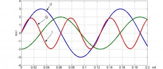
Consider a three-phase power system
Such chains can be connected in a star or triangle. For ease of reading circuits and to avoid phase errors, it is customary to designate phases as U, V, W or A, B, C.
Star connection diagram:
Star phase connection diagram
For a star connection, the total voltage at point N is zero. The power of the three-phase current in this case will also be a constant value, in contrast to the single-phase one. This means that a three-phase system is balanced, unlike a single-phase one, that is, the power of a three-phase network is constant. Instantly, the value of the total three-phase power will be equal to:
In this type of connection there are two types of voltage - phase and linear. Phase is the voltage between the phase and the zero point N:
Phase voltage in the circuit
Linear – between phases:
Line voltage
Therefore, the total power of a three-phase network for this type of connection will be equal to:
But since the linear and phase voltages differ from each other in , the sum of the phase powers is considered. When calculating three-phase circuits of this type, it is customary to use the formula:
Accordingly, for active:
For reactive:
Active power measurement in three-phase circuits
Measurement of active power in three-phase circuits is carried out using three, two or one wattmeters, using various circuits for their connection. The connection diagram of wattmeters for measuring active power is determined by the network diagram (three or four wires), the phase connection diagram of the receiver (star or triangle), the nature of the load (symmetrical or asymmetrical), and the availability of the neutral point.
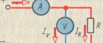
With an asymmetrical load in a four-wire circuit, the active power is measured with three wattmeters (Fig. 19), each of which measures the power of one phase - phase power.
Calculation
Calculating the power of a three-phase system is difficult, because the current in the network is not constant, but alternating.
With constant current, power is calculated by multiplying voltage and current. With alternating current, all quantities are unstable due to the presence of several phases. The connection method also matters. With a single-phase system, power is also calculated by multiplying voltage and current, but taking into account the power factor-cos, which characterizes the phase shift between voltage and current for a reactive load.
The calculation takes place according to the following formula for the complete calculation of current power in a three-phase network:
Ptotal=Uа∙Iа∙cosа+ Ub∙Ib∙cosb+ Uc∙Ic∙cosc
where U is voltage, I is current, cos is power factor, a , b and c are phases.
Power measurement in three-phase circuits is carried out with a wattmeter.
With a symmetrical load, only one phase is measured and the measurement result is multiplied by 3. When measuring 3 phases at once, 3 devices will be required. In the absence of the “zero” phase, the measurement is carried out by 2 devices and the power calculation is calculated according to Kirchhoff’s 1st law:
Ia+Ib+Ic=0
The sum of the readings of two wattmeters will give an indicator of the power of the three-phase circuit.
Find out the power consumption of electricity
How to calculate power and why is it necessary?
Knowing the maximum power consumption will allow you to organize the correct power supply for your apartment or household.
To calculate it, it is necessary to calculate the power consumption of single-phase devices and study three-phase devices. The parameters are indicated in the technical data sheets of the products or in the technical reference book. Knowing these parameters and using the formula for calculating power, the current strength in a three-phase system is determined, which puts a load on the electrical wiring.
Using the information obtained, fuses and wires are selected that will be used when laying the internal electrical network.
We calculate the power of a three-phase network
For convenience and quick calculations, there are online services with calculators in which you can quickly calculate the network capacity by entering indicators known to the user.
Application
Scope of application of DPM
Designed for use in energy management systems where there are high demands on the quality of energy management.
- Electricity consumption analysis systems.
- In medium and low voltage distribution boards.
- Energy management systems.
- In reactive power compensation systems.