What is electric power
When describing electrical power in a broad sense, we are most often talking about the energy or force with which some object or action is endowed. For example, it can be defined for an explosion or a mechanism, such as an engine. This parameter is associated with force and depends on it, which is why these phenomena are often confused.
The difference is that force affects physical actions, that is, work is performed. If it is done in the specified time, then through these two parameters the power value can be calculated.
In the case of electricity, there are two types:
- Active - turns into energy of heat, light, mechanical action, etc. It is measured in watts and calculated by the formula 1 W = 1 V x 1A. But in practice, this indicator is most often expressed in kilowatts and megawatts.
- Reactive – load arising due to oscillations within the electromagnetic field. The unit of measurement is volt-amperes (VA), they are calculated as Q=U x I x sin angle. The latter means a phase change between current and voltage reduction.
In practice, the differences between both types are best seen using the example of heating elements and electric motors. Heating elements are assembled from a material with high resistance, so they convert all the electricity received into heat. The electric motor has parts that have inductance, that is, part of the current returns to the network and can negatively affect it, creating overloads.
Relationship between useful power and efficiency
Efficiency factor (efficiency) is a dimensionless quantity, expressed numerically as a percentage. Efficiency is denoted by the letter η.
kVA to kW - how to correctly convert power
The formula looks like:
η = A/Q,
Where:
- A – useful work (energy);
- Q – energy expended.
As the efficiency increases in various engines, it is permissible to build the following line:
- electric motor – up to 98%;
- ICE – up to 40%;
- steam turbine – up to 30%.
In terms of power, efficiency is equal to the ratio of useful power to the total power delivered by the source. In any case, η ≤ 1.
Important! Efficiency and Ppol are not the same thing. In different work processes, they achieve the maximum of one or the other.
Obtaining maximum energy at the output of the IP
For your information. To increase the efficiency of cranes, injection pumps or aircraft engines, it is necessary to reduce the friction forces of mechanisms or air resistance. This is achieved by using a variety of lubricants, installing higher-class bearings (replacing sliding with rolling), changing the wing geometry, etc.
The maximum energy or power at the output of the IP can be achieved by matching the load resistance Rн and the internal resistance R0 of the IP. This means that Rн = R0. In this case, the efficiency is 50%. This is quite acceptable for low-current circuits and radio devices.
However, this option is not suitable for electrical installations. To avoid wasting large amounts of power, the operating mode of generators, rectifiers, transformers and electric motors is such that the efficiency is approaches 95% and above.
Graph of dependence of Рpol and η on current in the circuit
Achieving maximum efficiency
The formula for the efficiency of a current source is:
η = Pн/Ptotal = R/Rн+r,
Where:
- Pn – load power;
- Ptotal – total power;
- R is the total resistance of the circuit;
- Rн – load resistance;
- r – internal resistance of IT.
As can be seen from the graph shown in Fig. higher, the power Pn tends to zero as the current in the circuit decreases. The efficiency, in turn, will reach its maximum value when the circuit is open and the current is zero; if there is a short circuit in the circuit, it will become zero.
If we look at an elementary heat engine consisting of a piston and a cylinder, then its compression ratio is equal to the expansion ratio. Increasing the efficiency of such a motor is possible if:
- initially high parameters: pressure and temperature of the working fluid before expansion begins;
- bringing their values closer to environmental parameters at the end of expansion.
Achieving ηmax is possible only with the most effective change in the pressure of the working component in the rotational movement of the shaft.
For your information. The thermal efficiency increases with increasing proportion of heat supplied to the working fluid, which is converted into work. The supplied heat is divided into two types of energy: internal in the form of temperature and pressure energy.
Mechanical work, in fact, is performed only by the second type of energy. This gives rise to a number of disadvantages that slow down the process of increasing efficiency:
- some of the pressure goes to the external environment;
- achieving maximum efficiency is impossible without increasing the percentage of pressure energy used for conversion into work;
- it is impossible to increase the efficiency of heat engines without changing S the surface of pressure application, and without removing this surface from the point of rotation;
- the use of only a gaseous working fluid does not contribute to increasing η of heat engines.
To achieve a high efficiency of a heat engine, you need to make a number of decisions. The following device models contribute to this:
- introduce another working fluid with different physical properties into the expansion cycle;
- make the most of both types of energy of the working fluid before expansion;
- generate additional working fluid directly during gaseous expansion.
Information. All modifications to internal combustion engines in the form of: a turbocharger, the organization of multiple or distributed injection, as well as increasing air humidity, bringing the fuel to a state of steam during injection, did not produce tangible results in a sharp increase in efficiency.
Internal combustion engine efficiency
What formula is used to calculate the power of electric current?
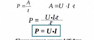
This value is tied simultaneously to several physical parameters. Voltage is the work required to move 1 coulomb. Force means the number of coulombs that travel in 1 second. If you multiply the current by the voltage, it equals the amount of work done per second. To calculate the power of electric current, the formula is not difficult to derive.
She looks like
P = A / t = I x U,
the designations are as follows:
- P – current power in watts (W);
- A – its work on a given section of the circuit in joules (J);
- t – time during which the work was completed (in seconds);
- U – electrical voltage for a section of the circuit in volts (V);
- I – power in amperes (A).
This formula shows that the dependence of power on voltage and current is the same in this combination. One indicator can be higher and thereby compensate for the other to provide a powerful electric current. This feature ensures the transmission of electricity over long distances. Its transformation occurs through control transformers at substations.
Correct determination of power is critical to comply with safety regulations when operating the electrical network and avoid fires. This can happen if the wiring is incorrect. To measure, it is necessary to use special instruments, but this is not always possible.
Definition of power for alternating current:
- using an ammeter;
- according to the formula P= U x I using the values at the specified time;
- according to the formula P= U x I x cos φ, if there is a phase shift.
The symbol φ stands for power factor. When only light or heating devices are connected to the network, it is equal to 1; for more complex and powerful industrial-type equipment, the figure is 0.8. The formula for calculating power through resistance in a DC network is P = IU.
Power supply parameters
Electric current power
In practice, you often have to think about what the power of the current source should be, how many watts (W) or kilowatts (kW) are needed to ensure uninterrupted operation of the device. To understand the essence, you need to have an understanding of such concepts used in physics as:
- total circuit energy;
- EMF and voltage;
- internal resistance of the power supply;
- losses within the individual entrepreneur;
- useful power.
Regardless of what kind of energy the source produces (mechanical, electrical, thermal), its power should be selected with a small margin (5-10%).
Total circuit energy
When a load is connected to the circuit, which will consume energy from a current source (IT), the current will do work. The energy released by all consumers and circuit elements included in the circuit (wires, electronic components, etc.) is called total energy. The energy source can be any: generator, battery, thermal boiler. The total energy value will be the sum of the energy spent by the source on losses and the amount spent on performing specific work.
EMF and voltage
What is the difference between these two concepts?
EMF is electromotive force, it is the voltage that external forces (chemical reaction, electromagnetic induction) create inside a current source (IT). EMF is the force of movement of electrical charges in IT.
EMF definition
For your information. It seems possible to measure the value of E (EMF) only in idle mode (idle). Connecting any load causes a loss of voltage inside the power supply.
Voltage (U) is a physical quantity representing the potential difference ϕ1 and ϕ2 at the output of the voltage source (VS).
Potential difference
Net power
The definition of the concept of total power is used not only in relation to electrical circuits. It is also applicable to electric motors, transformers and other devices capable of consuming both active and reactive components of energy.
Losses inside the power supply
Similar losses occur at the internal resistance of a two-terminal network. For a battery, this is the electrolyte resistance; for a generator, this is the winding resistance, the lead wires of which come out of the housing.
Internal power supply resistance
You won’t be able to simply measure R0 with a tester; you definitely need to know it to calculate P0 losses. Therefore, indirect methods are used.
An indirect method for determining R0 is as follows:
- in x.x mode measure E (B);
- when the load Rн (Ohm) is turned on, Uout (V) and current I (A) are measured;
- The voltage drop inside the source is calculated using the formula:
U0=E-Uout.
At the last stage, R0=U0/I is found.
Circuit for measuring R0
What does current power depend on?
Electric current strength and voltage are the two main components that make up this indicator. In practice, this can easily be explained using the example of a small light bulb receiving a current of 1 A at a voltage of 1 V. Its power will be 1 W.
A more realistic example is accounting for consumed electricity using the formula W=IUt, where t is the operating time. The higher it is, the greater the volume of electricity and the higher the bill for its payment in the utility bill.
Why Circuit Reactance Affects AC Power
A sinusoidal voltage harmonic, entering a resistive resistance, changes the magnitude of the current without its deviation on the complex plane.
Such current performs useful work with minimal energy losses, generating active power. The frequency of the signal does not have any effect on it.
The resistance of the capacitor and inductance depends on the frequency of the harmonic. Its opposition deflects the direction of the current on each of these elements in different directions.
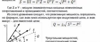
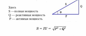
Such processes are associated with the loss of part of the energy for useless transformations. They consume power Q, which is called reactive. Its influence on the total power S and the connection with active P is conveniently represented graphically by a right triangle.
I wanted to draw it against the background of equipment made from piles of porcelain and metal, where I had to work for quite a long time. Got distracted. Don't judge harshly for this.
Compare it with the resistance triangle I published earlier. Do you find any common features?
They are the geometric proportions of the figure, the formulas describing them and the angle φ, which determines the total power loss. Let me move on to a more detailed consideration of them.
Load efficiency
The efficiency of electrical appliances does not depend on the battery and never reaches 100%. The exception is air conditioners and refrigerators that operate on the principle of a heat pump: cooling one radiator occurs by heating the other. If you do not take this point into account, the efficiency will be above 100%.
Energy is spent not only on performing useful work, but also on heating wires, friction and other types of losses. In lamps, in addition to the efficiency of the lamp itself, you should pay attention to the design of the reflector, in air heaters - on the efficiency of heating the room, and in electric motors - on cos φ.
Knowing the useful power of the power supply element is necessary to perform calculations. Without this, it is impossible to achieve maximum efficiency of the entire system.
Measurements
As shown above, some initial data can be obtained through practical measurements. The features of typical specialized devices are noted below.
Direct measurements
Wattmeters are produced in different modifications for ~220V and ~380V networks. Appropriate corrections are made during work operations. The probes should be connected taking into account the manufacturer's instructions and the appropriate location of the conductors.
As a rule, in device designs two coils are used with parallel and serial connection to the load. For increased accuracy, use professional instruments of the “laboratory” category.
Indirect measurements
These operations are performed using multimeters. Resistance, current and voltage are measured, after which the power is calculated.
Phase meters
These instruments measure the phase shift between several electrical parameters. With such a device, cos ϕ can be determined if the passport value is not in the accompanying documents for the equipment.
cos regulation
The negative impact of reactive components noted above is compensated for by special additions to the overall electrical circuit. Calculations are performed using the presented formulas.
METHOD AND PROCEDURE OF MEASUREMENTS
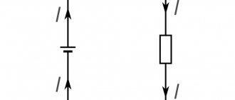
Assemble the circuit shown in Fig. on the screen. 2. To do this, first click the left mouse button above the emf button. at the bottom of the screen. Move the mouse marker to the working part of the screen where the dots are located. Click the left mouse button in the working part of the screen where the emf source will be located.
Next, place a resistor in series with the source, representing its internal resistance (by first pressing the button at the bottom of the screen) and an ammeter (the button is in the same place). Then arrange the load resistors and voltmeter in the same way, measuring the voltage across the load.
Connect the connecting wires. To do this, click the wire button at the bottom of the screen, and then move the mouse marker to the working area of the circuit. Click with the left mouse button in the areas of the working area of the screen where the connecting wires should be located.
4. Set parameter values for each element. To do this, left-click on the arrow button. Then click on this element. Move the mouse marker to the slider of the regulator that appears, click on the left mouse button and, holding it down, change the parameter value and set the numerical value indicated in Table 1 for your option.
Table 1. Initial parameters of the electrical circuit
| option |
5. Set the external circuit resistance to 2 Ohms, press the “Count” button and write down the readings of electrical measuring instruments in the corresponding lines of Table 2.
6. Use the regulator slider to consistently increase the resistance of the external circuit by 0.5 Ohms from 2 Ohms to 20 Ohms and, pressing the “Count” button, record the readings of electrical measuring instruments in Table 2.
7. Calculate using formulas (2), (7), (8), (9) P 1, P 2, P total and h
for each pair of voltmeter and ammeter readings and write the calculated values in Table 2.
8. Construct on one sheet of graph paper graphs of the dependence P 1 = f (R), P 2 = f (R), P total = f (R), h = f (R) and U = f (R).
9. Calculate the measurement errors and draw conclusions based on the results of the experiments.
Table 2. Results of measurements and calculations
| P full, VT |
Power of some electrical appliances
When equipping a modern apartment, it is often necessary to solve problems of coordinating loads in individual lines. It is necessary to properly install a circuit breaker to prevent emergency situations. They start by clarifying the wiring parameters. Next, the groups of connected household appliances are checked.
Typical power consumption (W):
- personal computer – 170-1,250;
- laptop – 40-280;
- LCD TV – 120-265;
- iron – 450-1850;
- air conditioning – 1,200 – 2,500.
Which machine is suitable is determined taking into account all significant factors. Particular attention is paid to loads with high values of the reactive component of power.
What formula is used to calculate
Mechanical Power Formula - Average and Instantaneous Power
The following paragraphs describe in detail typical situations (connected devices):
- constant voltage source (LEDs);
- ~220V, single phase (kitchen hood);
- ~380V, three phases (machine).
Calculation of current strength by power and voltage in a DC network
Using the principles we have learned, you can figure out how to calculate power (example):
- several LEDs are connected in series to a 5 V source;
- measure the current in the circuit using a multimeter (0.85 A);
- to determine the number of watts, the formula “P = I * U” will help you find out the result: 5 * 0.85 = 4.25 W.
How to find out the power of a single-phase load
Without correction factors, you can apply a similar algorithm when connecting an incandescent light bulb. However, in the example under consideration (hood), the AC power is calculated using the formula, taking into account the inductive parameters of the electric motor. In this case, a special correction factor is used - cosϕ.
Capacity Triangle
The following algorithm shows how to determine power:
- take the cosϕ value from the accompanying documentation (for example, 0.75);
- Manufacturers indicate the same data on type plates;
- measure current (1.25 A);
- voltage is known - 220 V;
- to determine the current power, the formula is supplemented with the corresponding multiplier:
Pact = 1.25 * 220 * 0.75 = 206.25 W.
How to find current power in a three-phase network
In these networks, electricity is supplied to consumers through different circuits. Instead of “phase” in this case, the concept of “linear” voltage is used, which is measured between individual conductors (Ulin = 380V). To calculate the power correctly, an additional multiplier is used (√3 = 1.7321).
Average P in active load
Knowing the AC power (350 W), after a simple transformation of the basic formula, you can calculate:
I = P/ (U * √3 * cosϕ) = 350 / (380 * 1.7321 * 0.75) = 350/ 493.6485 = 0.7 A.
Definition and formula of useful power
It is worth considering the concept of useful power and the formula using the example of an electrical circuit. The power that the power source (PS), in particular current, develops in a closed circuit will be the total power.
Circuit diagram
The circuit includes: a current source with EMF (E), an external circuit with a load R and an internal circuit of a power supply whose resistance is R0. The formula for total (total) power is:
Ptotal = E*I.
Here I is the value of the current passing through the circuit (A), and E is the value of the emf (B).
Attention! The voltage drop in each section will be equal to U and U0, respectively.
So the formula will take the form:
Ptotal = E*I = (U + U0) *I = U*I + U0*I.
It can be seen that the value of the product U*I is equal to the power supplied by the source to the load and corresponds to the useful power Ppol.
The value equal to the product U0*I corresponds to the power that is lost inside the power supply for heating and overcoming the internal resistance R0. This is the power loss P0.
The values substituted into the formula show that the sum of useful and lost power makes up the total power of the IP:
Ptotal=Pfloor+P0.
Important! When operating any apparatus (mechanical or electrical), the useful power will be that which remains to perform the required work after overcoming the factors causing losses (heating, friction, counteracting forces).
Current measuring instruments
Electrical measuring instruments are a special type of devices that are used to measure many electrical quantities. These include:
- AC ammeter;
- AC voltmeter;
- Ohmmeter;
- Multimeter;
- Frequency meter;
- Electric meters.
Ammeter
To determine the current strength in an electrical circuit, you need to use an ammeter. This device is connected to the circuit in series and, due to its negligible internal resistance, does not affect its state. The ammeter scale is graduated in amperes.
In a classic device, a measured current passes through an electromagnetic coil, which creates a magnetic field that causes the magnetic needle to deflect. The deflection angle is directly proportional to the measured current.
Classic ammeter
An electrodynamic ammeter has a more complex operating principle. It contains two coils: one is movable, the other stands still. They can be connected to each other in series or in parallel. When current passes through the coils, their magnetic fields begin to interact, which as a result causes the moving coil with an arrow attached to it to deviate by a certain angle proportional to the magnitude of the current being measured.
Voltmeter
A voltmeter is used to determine the voltage (potential difference) across a section of the circuit. The device must be connected parallel to the circuit and have high internal resistance. Then only hundredths of the current will enter the device.
School voltmeter
The principle of operation is that inside the voltmeter there is a coil and a series-connected resistor with a resistance of at least 1 kOhm, on which the volt scale is calibrated. The most interesting thing is that the resistor actually registers the current strength. However, the divisions are selected in such a way that the readings correspond to the voltage value.
Ohmmeter
This device is used to determine electrically active resistance. The principle of operation is to change the measured resistance into a voltage directly dependent on it thanks to an operational amplifier. The desired object must be connected to a feedback circuit or to an amplifier.
If the ohmmeter is electronic, then it will work on the principle of measuring the current flowing through the required resistance at a constant potential difference. All elements are connected in series. In this case, the current strength will have the following dependence:
I = U/(r0 + rx),
where U is the emf of the source, r0 is the resistance of the ammeter, rx is the desired resistance. According to this dependence, resistance is determined.
Electronic ohmmeter
Multimeter
The devices given as an example are used today only in schools for physics lessons. Multimeters were invented for professional tasks. The most common device includes simultaneously the functions of an ammeter, voltmeter and ohmmeter. The device can be either easily portable or huge stationary with a large number of possibilities. The name “multimeter” was first applied specifically to a digital meter. Analog devices are more often called “avometer”, “tester” or simply “Tseshka”.
Universal multimeter
The work of current is a complex but very important topic in electrodynamics. Without knowing it, you will not be able to solve even the simplest problems. Even electricians use job finding formulas to make the necessary calculations.
What is the thermal power of a resistor
Another name is dispersion. This concept refers to the maximum currents that can flow through it without harm to carry out work and generate EMF in contacts, etc.
Important! For each electrical circuit, the dissipation parameters are selected individually.
Calculated using a physical formula with algebraic values: P = I * R.
In SI:
- I – current strength, Ampere.
- R – resistance, Ohm.
- P – power, W.
In physical terms, dissipation is the ability of a conductor to transfer heat to the environment in an amount that does not harm the components of the element itself. This is a very important parameter, since the serviceability and durability of the electrical appliance depends on it.
Important! All components operate according to Ohm's law, but the heating itself occurs due to the difference in voltage values at the input and output. This is the main condition for the movement of charged particles through a conductor.
Selection of circuit breaker rating
Current source efficiency
To solve practical problems when connecting several consumers to a standard 220 V home network, the total current strength in individual lines is calculated.
Calculation procedure for one household air conditioner:
- power consumption – 1,250 W;
- cosϕ – 0.75;
- I = 1,250/ (220 * 0.75) = 7.58 A.
Other consumers make calculations in a similar way. Less powerful devices are combined into a unit for connection to one line. Make the necessary adjustments taking into account placement in order to economically use cable products. A suitable machine is selected from the standard model range in the higher side of the nominal value (with a reserve of current strength).
Next, check the compliance of the conductors. The cross-sectional area is calculated using the well-known geometric formula:
S = ¼ * π * d2.
Next, according to the table from the PUE, select the appropriate option. For the example presented above, when connecting only one air conditioner, it is enough to use a copper conductor with a cross-sectional area of 1.5 mm square. This is enough for long-term transmission of current up to 19 A.