The number of mobile communications devices in active use is constantly growing. Each of them comes with a charger supplied in the kit. However, not all products meet the deadlines set by the manufacturers. The main reasons are the low quality of electrical networks and the devices themselves. They often break down and it is not always possible to quickly purchase a replacement. In such cases, you need a circuit diagram for a phone charger, using which it is quite possible to repair a faulty device or make a new one yourself.
Main faults of chargers
The charger is considered the weakest link in mobile phones. They often fail due to poor quality parts, unstable mains voltage or as a result of ordinary mechanical damage.
The simplest and best option is to purchase a new device. Despite the differences in manufacturers, the general schemes are very similar to each other. At its core, this is a standard blocking generator that rectifies the current using a transformer. Chargers may differ in connector configuration, they may have different circuits of input network rectifiers, made in a bridge or half-wave version. There are differences in small things that are not of decisive importance.
As practice shows, the main faults of the memory are the following:
- Breakdown of the capacitor installed behind the mains rectifier. As a result of the breakdown, not only the rectifier itself is damaged, but also a constant resistor with low resistance, which simply burns out. In such situations, the resistor practically acts as a fuse.
- Transistor failure. As a rule, many circuits use high-voltage high-power elements marked 13001 or 13003. For repairs, you can use the domestically produced KT940A product.
- Generation does not start due to a breakdown of the capacitor. The output voltage becomes unstable when the zener diode is damaged.
sxemy-podnial.net
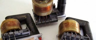
I present to your attention the power supply that I have finally produced.
PSU for low-voltage devices with charger and dials. Appearance
There were power supplies in front of him, but they were stillborn... No, I certainly used them, but not often... The fact is that making a good laboratory power supply for a radio amateur is an event of such importance as making a child in family life... And at the same time - a beloved child... You can sing an Ode to Love to the power supply if it turned out well. I can’t say that I’m one hundred percent satisfied with my design, but I’m happy. I embodied in it almost half of the plans for the power supply.
PSU for low-voltage devices with charger and dials. Scheme
For a radio amateur, it is important to choose the appropriate transformer and housing. And in this design almost everything coincided. Of course, there is almost no radiator in it, but the body is metal and does its job, especially since I don’t need high currents yet. Radio amateurs have been using integrated stabilizers for a long time, but in order to make them adjustable, they had to “sweat.” It turned out that only low-resistance variable resistors can be used in the general circuit, and I only found wire-wound ones. But four output voltages and two of them are adjustable, allow you to prototype virtually any low-voltage device. Since I now often turn to devices powered by mobile phone batteries, I made one adjustable voltage with an output voltage of 3 to 4.2 volts. I also made a simple charger for charging batteries of mobile devices with a charge current of up to 1 Ampere. And I also introduced continuity testing for acoustic devices with continuity testing into the power supply, since although they are not needed often, they are needed. And, perhaps, the most unpleasant thing for a modern radio amateur is the difficulty of purchasing output terminals. And if they are available, the radio amateur will think many times about installing such large parts on the structure. In my opinion, I have found a compromise solution.
Terminal block. Design
The design turned out to be easily repeatable, because it requires accessible electrical polyethylene terminal blocks and tinned sheet metal from any tin can. The photograph shows such a terminal block and a combined common strip. You can connect a wire to such a miniature terminal block at any time and clamp it with a screw or solder it to the petal. The charger can smoothly regulate the charging current and monitor the progress of the charge using a two-color LED. I also installed a mains power switch from the computer network carrier, which allows you to quickly turn the circuit on/off. I don’t show the printed circuit board, since it is individual.
PSU board assembled. Parts side installation
And one more thing: a trained radio amateur may object to me that it is not very correct that I used half-wave rectifiers, but I believe that for my purposes this is an acceptable compromise. Moreover, such rectifiers were used by foreign radio amateurs more than thirty years ago; a description of a similar design can be found in the magazine Radio No. 1, 1987.
PS: One of my friends, who gave me a diagram of electronic drums, also lived with such a problem. And although he had been a radio engineer for a long time, at home he used a power supply that he had made while still a novice radio amateur. In his words, and with them I agree, it’s easy to make a power supply, and at the same time incredibly difficult. Because, if you have already decided on a scheme and are selecting parts for your design, a worm of doubt gnaws at you from within - is this the right scheme... And, as a rule, the whole idea quickly falls apart...
Simple electronic circuit
The basis of many modern chargers are the simplest pulse circuits of blocking generators, containing only one high-voltage transistor. They are compact in size and capable of delivering the required power. These devices are completely safe to use, since any malfunction leads to a complete absence of voltage at the output. This prevents high unstabilized voltage from entering the load.
The rectification of the alternating voltage of the network is carried out by the diode VD1. Some circuits include an entire diode bridge of 4 elements. The current pulse is limited at the moment of switching on by resistor R1 with a power of 0.25 W. In case of overload, it simply burns out, protecting the entire circuit from failure.
To assemble the converter, a conventional flyback circuit based on transistor VT1 is used. More stable operation is ensured by resistor R2, which starts generation at the moment of power supply. Additional generation support comes from capacitor C1. Resistor R3 limits the base current during overloads and power surges.
How to make a 1.5 Ampere USB device
The voltage stabilizer of the L7805 series (current 1 A) or its analogue L7805CV (current 1.5 A) will be used as the “heart” of our charger. In fact, there can be a great variety of analogues used. In principle, the entire 7805 series of chips will be suitable for this. We will tell you more about analogues a little later.
The electrical circuit for connecting the stabilizer itself is simple; it is similar to the power stabilizer, which we talked about in our other article, “Power stabilizer in a 12-volt car.” We can say that these are brother microcircuits, only their stabilization voltages are different. The table below shows popular charger models.
Table of popular charger models.
Everything can be assembled either by surface mounting or on a board. It can be done on a regular, simple universal circuit board. In order for the microcircuit to develop its maximum supply current, it must be placed on a radiator. In our case, the radiator is taken from a computer processor. The stabilizer microcircuits themselves can be produced in various packages.
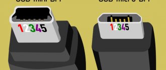
Connecting mini and micro USB plugs.
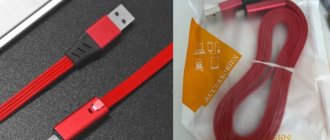
After you have assembled the USB device, you need to connect the USB connectors correctly. You can take a wire with a factory-made mini, micro USB plug, or you can buy an “empty” plug in a store and solder the wire to it. In my case, a mini USB plug was needed, which was soldered to the wire. The view is shown without the body.
Then, using a universal device, the voltage was checked again so as not to damage electronic gadgets. And then the battery of the audio player was already charged. Subsequently, the charger was installed under the instrument panel, and mini USB plugs were brought out: one on the instrument panel for the navigator, the second under the roof for the DVR.
Interesting read: What is a frequency converter and why is it needed.
5 volt device
However, the saga with the charger did not end there. Again, for a banal reason, when there is not enough supplied power or supply current for consumers, which is essentially the same thing, provided that the on-board voltage in the car is constant, since these values will be directly proportional. So, during long-term joint use of the navigator and the DVR, one microcircuit was not able to “pull” the power from these two devices, even with a radiator installed. As a result, it overheated and briefly turned off. At the same time, the navigator “cussed” when the power was turned off.
Capacitor - simple words about complex things.
Read more
How to make a charger for a car battery with your own hands.
Read more
How to calculate a resistor for an LED.
Read more
There seem to be two solutions to the problem. The first is to “fence the garden” and create parallel circuits, each of which will have its own consumers. Let's say one is a DVR, the other is a navigator. In fact, in the photo above, where two microcircuits are mounted on one radiator, this is what was done. However, it’s good if everything is limited to this, and if you need to connect a smartphone, tablet, something else... There is no way to do without more serious currents, and therefore without alternative options. An alternative option would be to use microassemblies with PWM modulation.
Phone charger.
So, such a scheme will not require large radiators for heat removal, and rather high currents will be provided. In general, everything will be as we need it. This option will be discussed further below. To reduce the voltage, a microcircuit, an inductor and elements for strapping are used. The microassembly is designated KIS3R33S. Its installation can be done according to the diagram from the Datasheet. However, by default with this configuration it has an output voltage of 3.3 volts, but for USB we need 5 volts.
It will be interesting➡ How to connect an indoor antenna to a TV: practical tips
In this case, it will be necessary to select resistors R1, R2. The table with recommended resistor values on which the supply voltage depends is also taken from the Datasheet. This feature of changing the voltage by selecting resistors makes this device a universal assistant if you need to power the load not only with a voltage of 5 volts as for USB. It should be noted that this device confidently holds a load with a current consumption of 3A, and peak performance can reach 4A. If you are too lazy to assemble such a device, have no time, or cannot do it, then you can purchase such an assembly for about $2 on well-known sites and online stores.
I must say that this Chinese voltage converter KIS-3R33S (MP2307) is quite good for its price, and is capable of delivering high currents, which we already know, up to 4A. This means that such an assembly can replace a pair of KRENOK or the 7805 series, which we talked about in the first part of the article. At the same time, it will be more compact and with higher efficiency. So, I bought this assembly. Then I also bought a distribution box, which are used for installing electrical wiring in apartments. This became the body of the converter - charger.
Related material: How to choose a digital-to-analog converter.
High reliability circuit
In this case, the input voltage is rectified by using a diode bridge VD1, a capacitor C1 and a resistor with a power of at least 0.5 W. Otherwise, while charging the capacitor when turning on the device, it may burn out.
Capacitor C1 must have a capacity in microfarads equal to the power of the entire charger in watts. The basic circuit of the converter is the same as in the previous version, with transistor VT1. To limit the current, an emitter with a current sensor based on resistor R4, diode VD3 and transistor VT2 is used.
How to make a portable charger with your own hands
Wireless charging has even greater capabilities. USB cables may stop working, break, or break. And then the charging process becomes problematic again.
The principle of operation is based on the transfer of current from a coil that creates a magnetic field inside the charger to a coil in the phone that is the receiver. As soon as the receiver itself is within the coverage area of the conductor, pulses of electromagnetic waves begin to be transmitted from device to device.
Of course, with all its convenience, there are also negative aspects of such charging:
- Frequent use of wireless charging can negatively affect the phone's battery capacity;
- lack of any official studies on the effects on humans and animals;
- the time it takes to fully charge a mobile phone battery will be longer than with conventional wired charging;
- you cannot use the phone while it is charging - if you take it from the stand, the process will be interrupted;
- if something is done incorrectly, for example, the wrong power is selected, then the gadget’s battery may become unusable;
- Often, when using wireless charging, the back cover of the phone overheats greatly, which negatively affects the life of the gadget and its performance.
The situation can be complicated by the fact that not all models support wireless charging. In this case, you will have to make not only a transmitter, but also a receiver that fits under the phone body. However, if the phone has such a function, then there should be no problems.
Devices for wireless charging are not cheap. But you can always make them yourself.
For this you will need:
- copper wire, diameter 1 mm (several meters, 25 turns);
- frame (5-7 cm);
- glue;
- soldering iron and related equipment;
- capacitor;
- 10 Ohm and 1 K resistor (2 pcs);
- transistor;
- mobile phone charger to power the transmitter.
So, let's start assembling a wireless phone charger.
- The copper wire needs to be wound in a spiral; you only need to make 25 turns. From the start of unwinding, leave a tail 5 cm long (we consider it a “plus”).
- During the wrapping process, lubricate the spiral with glue so that it holds its shape. At the end of the process, let it dry. Glue can be replaced with varnish.
- Assembling the pulse generator. We do everything according to the plan.
- We connect the coil.
The finished transmitter can be placed in any housing; it is only important that the walls are thin and do not interfere with the transmission of pulses.
If your phone model does not support wireless charging, then the next step is to fix it.
To do this you need to use:
- capacitors for 10n, 100n and 10u;
- diode;
- Voltage regulator;
- wire 30 turns, diameter 0.4 mm;
- soldering iron;
- glue.
We also begin assembly by winding the wire into a reel. Now there should be 30 turns. They also need to be lubricated with glue or varnish during the process to secure them. Then we assemble the receiver itself, focusing on the diagram below.
Next, you need to place the resulting receiver in the phone body and solder “+” and “-” to the corresponding connector wires to enable charging in the phone. It is important to do this very carefully so as not to damage anything. The branching of wires in gadgets can be seen in the picture below. Pay attention to the leftmost and rightmost wiring.
When everything is ready, you need to connect your made transmitter to the network and bring the phone as close to it as possible. The voltage and, accordingly, the charging speed depend on this.
When you place your phone within range of the battery you created, it should begin charging. You don’t need to connect anything separately and you don’t need to make any settings on your phone. If nothing works, then most likely you connected the wires poorly somewhere. Therefore, it is recommended to check the operation of devices before placing them under enclosures.
Another way to create a wireless charger with your own hands is presented in the video
Happy end
Actually, this is where the handiwork was completed. During the entire process, the thought was obsessively swirling that I would now plug the charger into the network and find out what a Chinese fire dragon looks like. But nothing even started to smoke, and the charging worked as expected...
Moreover, before the modification, the LED simply glowed red during charging, but now it blinks from red to green. Here's an Easter egg from the Chinese brother.
But still, I recommend cutting off all electronics and using this charger simply as a housing. It’s better to create an 18650 charger using charge control modules, a video about which is at the beginning of the article. I recommend watching this video, I tried very hard to make it fun and educational)