Diagram and description
Somehow recently I came across a circuit on the Internet for a very simple power supply with the ability to adjust the voltage. The voltage could be adjusted from 1 Volt to 36 Volt, depending on the output voltage on the secondary winding of the transformer.
Take a close look at the LM317T in the circuit itself! The third leg (3) of the microcircuit is connected to capacitor C1, that is, the third leg is INPUT, and the second leg (2) is connected to capacitor C2 and a 200 Ohm resistor and is an OUTPUT.
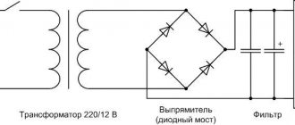
Using a transformer, from a mains voltage of 220 Volts we get 25 Volts, no more. Less is possible, no more. Then we straighten the whole thing with a diode bridge and smooth out the ripples using capacitor C1. All this is described in detail in the article on how to obtain constant voltage from alternating voltage. And our most important trump card in the power supply is the highly stable voltage regulator LM317T chip. At the time of writing, the price of this chip was around 14 rubles. Even cheaper than a loaf of white bread.
Circuit diagram of a simple power supply 5 V 1 A
Very often, to power various devices, for example, children's electronic toys, New Year's garlands, there is a need for a low-power 5 V power supply , this is a fairly common type of source and, if a laboratory power supply is suitable for setting up the assembled device, then of course you need to power the finished structure with your own BP 5V.
In this article I will try to describe step by step the construction of a 5 volt transformer power supply specifically for beginner radio amateurs. In general, I was prompted to write an article about BP by previous publications:
A simple LED flasher The simplest LED flasher Programmable garland switch LED garland on a microcontroller PWM Christmas tree garland switch
All of the above schemes require a 5V power supply as a primary or secondary source. Our 5 V power supply will be transformer, not pulse. In my humble opinion, a transformer power supply is easier to assemble and configure; perhaps in terms of cost and dimensions, a switching power supply is preferable, but if you have an old and, moreover, toroidal “trans” for 7 - 10 V lying around, then, as they say, God himself ordered it.
Block diagram of a 5 V power supply:
Each block is numbered A1-A6. In the schematic diagram, each block will be highlighted, so to speak, for clarity. Let's look at what each block is.
Surge filter (A1).
Designed to suppress high-voltage and high-frequency network interference. A varistor successfully copes with high-voltage interference. And the RC filter will deal with high-frequency interference.
A varistor is a semiconductor element characterized by resistance. It works as follows: in operating mode, the resistance of the varistor is high enough, the voltage does not exceed the threshold value of the varistor, and no current flows through it. As soon as the voltage reaches the “threshold”, the resistance of the varistor drops to almost several tens of Ohms and current begins to flow through it. Short-term high-voltage pulses are suppressed by the varistor, and longer overvoltage, as a rule, disables it, sometimes even with a loud bang.
In our 5 V power supply circuit we will use an RC filter; it is inferior in efficiency to an LC filter, but it is cheaper and quite suitable for our low-power power supply.
Previously, no one bothered with a surge filter, but now, no matter what household appliance you disassemble, you will definitely see a varistor; RC or LC filters are also found, but less often. This is caused by the massive use of switching power supplies, which transmit such a “porridge” of interference into the network that not every consumer can withstand it, so electrical manufacturers are trying to somehow protect their products. In a word, I do not recommend removing the surge protector from the power supply circuit.
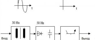
Transformer (A2).
In our 5 V power supply, the transformer plays a key role; it is the one that reduces (converts) the 220 V mains supply to low voltage. The transformer must be a power transformer, designed for a mains frequency of 50 Hz, with a primary winding of 220 V and one secondary winding of 7 - 10 V. The rated power of the transformer is 4 - 8 W. The design (toroidal, armored) in principle does not play a special role, whichever one you find.
Another point is that the effective voltage value (Ud) is indicated on the transformer, which can be checked by measuring it with a voltmeter. And at the output after the filter (block A4), essentially after the diode bridge and smoothing capacitor, we get the amplitude value (Ua). The relationship between the amplitude and effective voltages is as follows:
Ua = 1.41xUd
Those. if in the power supply the secondary winding of the transformer produces 7 - 10 V, then on the filter capacitor (A4) we will approximately get 10 - 14 V. Looking ahead, I will say that this is not dangerous for us, because The voltage stabilizer (A5) operates up to 40 V at the input. Theoretically, and practically, we can take a transformer with a high voltage and get the required 5 V at the output of the stabilizer. Where does the difference go? That's right - warm! But we don’t need this, we are building a rational 5 V power supply.
Rectifier (A3).
Converts AC input voltage to DC output. We will use a full-wave rectifier - a diode bridge.
Filter (A4).
Designed to smooth out voltage after the rectifier. A conventional electrolytic capacitor of sufficiently large capacity is used. The larger the capacitor capacity, the less ripple. In addition to capacitance, a capacitor also has such a parameter as voltage, be careful and take capacitors with a reserve. We agreed that in a 5 V power supply, the secondary winding of the transformer (A2) will be 7 - 10 V and, taking into account the increase in voltage by 1.41 times, we will take a capacitor of at least 25 V. At the moment when the capacitor is charging, flowing through the diode bridge the current increases because It is necessary to provide both charge and load. The reverse voltage of the diode is also high - the summation of the input and output voltages occurs. Therefore, diodes for the rectifier must be selected with a margin of parameters.
Voltage stabilizer (A5).
This is a microcircuit that serves to stabilize the input voltage range to a clearly defined output value. It is logical that the input voltage should be greater than the output voltage, as a rule, by no less than 3 V. The maximum threshold is usually limited to 30 - 40 V. It is better to take the stabilizer in a TO220 case and install it on a radiator, at least in our power supply at 5 I recommend doing this.
Indicator (A6).
In everyday life, we are already so accustomed to the fact that any equipment cheerfully winks at us with an LED when we turn it on, so I decided that an operating mode indicator would not hurt in a 5 V power supply. It consists of an LED and a current-limiting resistor. A red or green LED with a voltage of 1.5 V or 3 V, just calculate the resistor resistance correctly. The resistance of the current-limiting resistor is calculated using the formula:
R = (Upit - Ulight)/Ilight , where
Upit – power source voltage;
Ulight – forward voltage of the LED;
Ilight – forward current of the LED.
I recommend using an excellent calculator to calculate the current limiting resistor.
It's time to move from theory to practice. We present to your attention a schematic diagram of a 5 V power supply:
For clarity, blocks are highlighted in the power supply diagram according to the block diagram. Let's go through the diagram.
The first is fuse FU1, do not forget about it in your designs, this is a very important element. Often, by sacrificing himself, he saves the entire scheme. The fuse should be rated for a current of 0.15 A, you can take a more powerful one, but up to 0.5 A, this is for that extreme case when 0.15 A burns out. It all depends on the quality of the transformer. Do not put more than 0.5 A under any circumstances!
Switch SA1 is any suitable, it is better, of course, if it has two groups of contacts as shown in the diagram. Perfect for 250 V, 6 A. I don’t recommend installing it with a backlight in the power supply; we will have an LED as an indicator, which is located at the output of the power supply and, unlike the neon, the button in the button signals the operation of all upcoming components.
Next, according to the 5 V power supply circuit, there is a varistor RU1. You can use any, I installed JVR-07N471K. The main thing is that the so-called classification voltage is 470 V, no less - it will heat up, and no more - it will transmit overvoltage.
The resistance of resistors R1 and R2 is 5 - 20 Ohms, power up to 2 W. If, when assembling the power supply, you find these resistors nearby, put heat shrink or cambric on them, so they need to be isolated from each other, because the resistors’ own insulation is unreliable. On the printed circuit board proposed below, these resistors are spaced apart, however, excess insulation will not harm.
Non-electrolytic film capacitor C1 of the K73-17 series, rated voltage 630 V, capacity 0.1 - 0.47 µF.
We have already talked about transformer T1 for a 5 V power supply, let me briefly remind you - the primary winding is 220 V, the secondary is 7 - 10 V, power is 4 - 8 W.
I recommend taking the VD1 diode bridge ready-made, of course, if you wish, you can solder it from diodes. When connecting, look at the markings on the housing. If you still decide to assemble it from diodes, let me remind you that the cathode is marked with a strip on the diode body; how to identify the cathode in the diagram, see the figure, it is in red. As for the parameters, for our 5 V power supply we take a bridge with a reserve, I chose KBL01.
Power supply filter, also known as electrolytic capacitor C2 type K50-35. Electrolytic capacitors have polarity, a minus is marked on the case, a plus is indicated in the circuit, be careful if you mix it up, bang-bang is guaranteed. The same will happen if the supply voltage exceeds the rated value of the capacitor. Capacitance 2200 - 4700 µF, less is not possible due to increased ripple, more is no point. Voltage 25 V and above. Don’t forget, we agreed that in the assembled power supply the secondary winding is 10 V, no more, taking into account the increase by 1.41 times, we get 25 V with a margin. In general, when selecting a transformer, multiply the voltage supplied to the capacitor by about 1.5 (i.e. i.e. taking into account 1.41) - this will be a margin of safety.
The voltage regulator is also an important component of the 5V power supply circuit . There are domestic ones, there are imported analogues, it’s up to you to choose. I settled on the L7805A, maximum input voltage - 35 V, output - 5 V, output current up to 1 A, TO220 package. Capacitor C3 is recommended to prevent self-excitation of stabilizers. An ordinary ceramic multilayer K10-17B series, capacitance 0.1 - 4.7 µF, is suitable.
The last element of the 5 V power supply is an operation indicator. LED HL1 and current limiting resistor R3. LED AL307BM, resistor resistance according to calculations is 300 Ohms, power 0.125 W. An LED, like a diode, has a cathode, and do not mix up the anode when connecting. A multimeter in ohmmeter mode or in diode testing mode will help you determine the polarity; if connected correctly, the LED will light up.
The 5 V power supply is assembled on a one-sided foil fiberglass sheet measuring 60x26 mm. Fuse FU1, switch SA1 and transformer T1 are located separately. The HL1 LED is optional; it can be placed on the case.
The printed circuit board of the 5 V power supply from the elements side looks like this:
And from the element pins it looks like this:
I suggest you download the 5V power supply PCB in .lay format at the end of this article.
5 V power supply adjustment .
list of files
bp_5v.lay
5V power supply circuit board
- Downloads: 1676
- Size: 23 Kb
Rate this article Rating 4.53 (72 Votes)
Description of the chip
LM317T is a voltage regulator. If the transformer produces up to 27-28 volts on the secondary winding, then we can easily regulate the voltage from 1.2 to 37 volts, but I would not raise the bar to more than 25 volts at the transformer output.
The microcircuit can be executed in the TO-220 package:
or in D2 Pack housing
It can pass a maximum current of 1.5 Amps, which is enough to power your electronic gadgets without voltage drop. That is, we can output a voltage of 36 Volts with a current load of up to 1.5 Amps, and at the same time our microcircuit will still output 36 Volts - this, of course, is ideal. In reality, fractions of volts will drop, which is not very critical. With a large current in the load, it is more advisable to install this microcircuit on a radiator.
In order to assemble the circuit, we also need a variable resistor of 6.8 Kilo-Ohms, or even 10 Kilo-Ohms, as well as a constant resistor of 200 Ohms, preferably from 1 Watt. Well, we put a 100 µF capacitor at the output. Absolutely simple scheme!
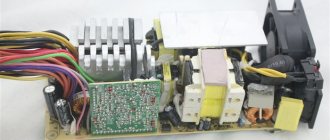
Repair of switching power supplies
Malfunctions of switching power supplies, repair
Based on the circuit diagram of the switching power supply, we will move on to its repair. Possible malfunctions:
- If the varistor and the fuse at the input or VCR1 have burned out, then we look further. Because they just don't burn.
- The diode bridge burned out. Usually this is a microcircuit. If there is a protective diode, then it usually lights up. They need to be replaced.
- The 400V capacitor C1 is damaged. Rarely, but it happens. Often its malfunction can be identified by its appearance. But not always. Sometimes a seemingly good capacitor turns out to be bad. For example, by internal resistance.
- If the switching transistor burns out, then unsolder it and check it. If faulty, replacement is required.
- If the PWM regulator does not work, then change it.
- Short circuit, as well as breakage of the transformer windings. The chances of repair are minimal.
- An optocoupler malfunction is an extremely rare case.
- Malfunction of the TL431 stabilizer. For diagnostics, we measure the resistance.
- If there is a short circuit in the capacitors at the output of the power supply, then we unsolder it and diagnose it with a tester.
Examples of repair of switching power supplies
For example, consider the repair of a switching power supply for several voltages.
The malfunction was the absence of output voltage at the output of the block.
For example, in one power supply two capacitors 1 and 2 in the primary circuit turned out to be faulty. But they weren't swollen.
On the second one the PWM controller did not work.
All the capacitors in the picture appear to be working, but they have high internal resistance. Moreover, the internal ESR resistance of capacitor 2 in the circle turned out to be several times higher than the nominal one. This capacitor is in the PWM regulator circuit, so the regulator did not work. The functionality of the power supply was restored only after replacing this capacitor. Because PWM worked.
Repair of computer power supplies
An example of repairing a computer power supply. An expensive 800 W power supply came in for repair. When it was turned on, the circuit breaker was knocked out.
It turned out that the short circuit was caused by a burnt-out transistor in the primary power circuit. The repair price was 3,000 rubles.
It makes sense to repair only high-quality, expensive computer power supplies. Because repairing a power supply may be more expensive than a new one.
Assembly in hardware
Previously, I had a very bad power supply with transistors. I thought, why not remake it? Here is the result
Here we see the imported GBU606 diode bridge. It is designed for a current of up to 6 Amps, which is more than enough for our power supply, since it will deliver a maximum of 1.5 Amps to the load. I installed the LM on the radiator using KPT-8 paste to improve heat transfer. Well, everything else, I think, is familiar to you.
And here is an antediluvian transformer that gives me a voltage of 12 volts on the secondary winding.
We carefully pack all this into the case and remove the wires.
So what do you think ?
The minimum voltage I got was 1.25 Volts, and the maximum was 15 Volts.
I set any voltage, in this case the most common are 12 Volts and 5 Volts
Everything works great!
This power supply is very convenient for adjusting the speed of a mini-drill, which is used for drilling circuit boards.