Features of creating a power supply
All technical devices need power. The difference is the current and voltage that produce power.
All power supply devices are divided into two types:
- Transformer. These power supplies are very easy to manufacture for beginners in radio engineering. The low level of magnetic radiation is a clear advantage of these units. Their only drawback is the volumetric transformer, which makes the device quite large;
- Transformerless. More miniature, since there is no bulky transformer in the classic form. A tiny high-frequency transformer reduces the number of turns and dimensions of the magnetic circuit.
The desire of radio amateurs to obtain miniature structures was the reason for the emergence of various microcircuits that contain many electrical elements.
Each electrical appliance is based on a microcircuit with a power supply of up to five volts. Additional elements can receive power up to twelve volts DC.
Everyone knows that the voltage in a regular outlet is two hundred and twenty volts, and the voltage frequency is fifty hertz; you cannot apply such voltage to a microcircuit, as it will immediately break. In this case, a power supply will help, which will reduce the voltage to the desired level. The design of the power supply is simple.
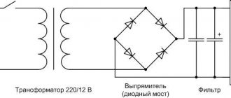
The main elements are:
- Transformer.
- Rectifier
- Filter.
- Stabilizer.
Add a link to a discussion of the article on the forum
RadioKot >Training >Analog technology >Assembling the first devices >
| Article tags: | Add a tag |
Power supply “It couldn’t be simpler.” Part two
Author: Published 01/01/1970
Yeah, did you come in yet? What, curiosity tormented you? But I'm very happy. No, really. Make yourself comfortable, now together we will make some simple calculations that are needed to assemble the power supply that we have already done in the first part of the article. Although it must be said that these calculations can be useful in more complex schemes.
So, our power supply consists of two main components - a rectifier, consisting of a transformer, rectifying diodes and a capacitor, and a stabilizer, consisting of everything else. Like real Indians, let's start from the end and calculate the stabilizer first.
Stabilizer
The stabilizer circuit is shown in the figure.
This is the so-called parametric
stabilizer. It consists of two parts: 1 - the stabilizer itself on a zener diode D with a ballast resistor Rb 2 - an emitter follower on a transistor VT.
The stabilizer ensures that the voltage remains what we need, and the emitter follower allows you to connect a powerful load to the stabilizer. It plays the role of an amplifier, or, if you like, a booster.
The two main parameters of our power supply are the output voltage and the maximum load current. Let's call them: Uout
is the voltage and
Imax
is the current.
For the power supply, which we discussed in the last part, Uout = 14 Volts, and Imax = 1 Ampere.
First, we need to determine what voltage Uin we must apply to the stabilizer in order to obtain the required Uout at the output. This voltage is determined by the formula:
Uin = Uout + 3
Where did the number 3 come from? This is the voltage drop across the collector-emitter junction of the VT transistor. Thus, for our stabilizer to operate, we must supply at least 17 volts to its input.
Let's move on.
Transistor
Let's determine what kind of transistor VT we need. To do this, we need to determine how much power it will dissipate.
We count:
Pmax=1.3(Uin-Uout)Imax
One point needs to be taken into account here. For the calculation, we took the maximum output voltage of the power supply. However, in this calculation, on the contrary, we must take the minimum voltage that the power supply produces. And in our case it is 1.5 volts. If this is not done, the transistor may be covered with a copper basin, since the maximum power will be calculated incorrectly. Take a look yourself:
If we take Uout=14 volts, then we get Pmax=1.3*(17-14)*1=3.9 W.
And if we take Uout = 1.5 volts, then
Pmax = 1.3 * (17-1.5) * 1 = 20.15 W
That is, if we did not take this into account, it would turn out that the calculated power is FIVE times less than the real one. Of course, the transistor would not like this very much.
Well, now we go into the directory and choose a transistor for ourselves. In addition to the power just received, it must be taken into account that the maximum voltage between the emitter and the collector must be greater than Uin, and the maximum collector current must be greater than Imax. I chose KT817 - a pretty decent transistor...
Phew, well, it looks like we got it done. Let's move on.
We consider the stabilizer itself.
First, let's determine the maximum base current of a freshly selected transistor (what did you think? In our cruel world, everyone consumes it - even the bases of transistors).
Ib max=Imax / h21E min
h21E min
- this is the minimum current transfer coefficient of the transistor and it is taken from the reference book. If the limits of this parameter are indicated there - something like 30...40, then the smallest one is taken. Well, in my reference book there is only one number written - 25, we will count with it, but what else is left?
Ib max=1/25=0.04 A (or 40 mA). Not a little.
Well, let's now look for a zener diode. You need to look for it using two parameters - stabilization voltage and stabilization current.
The stabilization voltage should be equal to the maximum output voltage of the power supply, that is, 14 volts, and the current should be at least 40 mA, that is, what we calculated. Let's go back to the directory...
D814D zener diode suits us terribly
, besides, I had it at hand.
But the stabilization current... 5 mA is not suitable for us. What are we going to do? We will reduce the base current of the output transistor. And to do this, we’ll add another transistor to the circuit. Let's look at the drawing. We added transistor VT2 to the circuit. This operation allows us to reduce the load on the zener diode by h21E times. h21E, of course, the transistor that we just added to the circuit. Without thinking too much, I took the KT315 from the pile of pieces of hardware. Its minimum h21E is 30, that is, we can reduce the current to 40/30 = 1.33 mA
, which is quite suitable for us.
Now let's calculate the resistance and power of the ballast resistor Rb.
Rb=(Uin-Ust)/(Ib max+Ist min)
where Ust is the stabilization voltage of the zener diode, Ist min is the stabilization current of the zener diode.
Rb = (17-14)/((1.33+5)/1000) = 470 Ohm.
Now let's determine the power of this resistor
Prb=(Uin-Ust)2/Rb.
That is
Prb=(17-14)2/470=0.02 W.
That's all. Thus, from the initial data - output voltage and current, we obtained all the elements of the circuit and the input voltage that should be supplied to the stabilizer.
However, let's not relax - the rectifier is still waiting for us. I think so, I think so (pun intended, though).
Rectifier
So, let's look at the rectifier circuit.
Well, here everything is simpler and almost on your fingers. Considering that we know what voltage we need to supply to the stabilizer - 17 volts, let's calculate the voltage on the secondary winding of the transformer. To do this, let's go, as in the beginning - from the tail. So after the filter capacitor we should have a voltage of 17 volts.
Considering that the filter capacitor increases the rectified voltage by 1.41 times, we get that after the rectifier bridge we should get 17/1.41 = 12 volts
. Now let’s take into account that we lose about 1.5-2 volts on the rectifier bridge, therefore, the voltage on the secondary winding should be 12+2=14 volts. It may well happen that such a transformer will not be found, don’t worry - in this case you can use a transformer with a voltage on the secondary winding of 13 to 16 volts.
Let's move on. Let's determine the capacitance of the filter capacitor.
Cf=3200In/UnKn
where In is the maximum load current, Un is the load voltage, Kn is the ripple factor.
In our case, In = 1 Ampere, Un = 17 volts, Kn = 0.01.
Cf=3200*1/14*0.01=18823.
However, since there is also a voltage stabilizer behind the rectifier, we can reduce the calculated capacitance by 5...10 times. That is, 2000 uF will be quite enough.
All that remains is to choose rectifier diodes or a diode bridge.
To do this, we need to know two main parameters - the maximum current flowing through one diode and the maximum reverse voltage, also through one diode.
The required maximum reverse voltage is calculated as follows:
Uarr max=2Un, that is, Uarr max=2*17=34 Volts.
And the maximum current for one diode must be greater than or equal to the load current of the power supply. Well, for diode assemblies, reference books indicate the total maximum current that can flow through this assembly.
Well, that seems to be all about rectifiers and parametric stabilizers. Ahead we have a stabilizer for the laziest - on an integrated circuit and a stabilizer for the most hardworking - a compensation stabilizer.
<<—Part 1—Part 3—>>
| What do you think of this article? | Did this device work for you? | |
| 81 | 1 | 7 |
| 7 | 1 |
Simple power supply
Often there is a need to power several microcircuits or transistors. In this case, you can make a low-power power supply.
Good options are 78L05, 78L12, 79L05, 79L08 stabilizers.
These designs are designed for a current of one hundred milliamps, although they are very miniature and compact. Their installation on the radiator is not required.
- Making your own power supply is easy. The voltage is supplied through a stabilizer.
- In this scheme, the stabilizer is a limiter on the flow of elements.
- The allowed value is one ampere, so the remaining elements of the block must be designed for a current of more than one ampere.
- That is, after equalization, the stabilizer input needs to be supplied a few volts more than the output for smooth operation.
- Do not overestimate the U value to prevent overheating of the microcircuit.
Accessories
To assemble a 12 Volt power supply circuit we will need:
- Thermistor;
- Capacitors (2 pcs.);
- Diode bridge;
- Drivers;
- Transformer;
- Diodes for output;
- Field effect transistors;
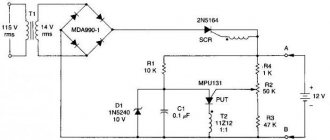
Adjustable power supply
The power supply can be made adjustable. The voltage input of this type should be no more than thirty volts, and the current strength should not be more than ten amperes. Be sure to build in short circuit protection.
Such a device can be made from inexpensive, publicly available parts. In the presented circuit, the stabilizer is designed for a current not exceeding one and a half amperes. The circuit includes a transistor that is capable of transmitting high voltage.
If you rotate the variable resistor knob, the voltage at the output of the structure changes. Besides. There are several shunt resistors with a resistance of two hundred ohms. After turning off the power supply, the capacitor is discharged through a resistor.
Diagram and description
Somehow recently I came across a circuit on the Internet for a very simple power supply with the ability to adjust the voltage.
The voltage could be adjusted from 1 Volt to 36 Volt, depending on the output voltage on the secondary winding of the transformer. Take a close look at the LM317T in the circuit itself! The third leg (3) of the microcircuit is connected to capacitor C1, that is, the third leg is INPUT, and the second leg (2) is connected to capacitor C2 and a 200 Ohm resistor and is an OUTPUT.
Using a transformer, from a mains voltage of 220 Volts we get 25 Volts, no more. Less is possible, no more. Then we straighten the whole thing with a diode bridge and smooth out the ripples using capacitor C1. All this is described in detail in the article on how to obtain constant voltage from alternating voltage. And our most important trump card in the power supply is the highly stable voltage regulator LM317T chip. At the time of writing, the price of this chip was around 14 rubles. Even cheaper than a loaf of white bread.
Charging from the power supply
Many who are a little versed in technology are wondering: how to make a charger for a computer from a power supply?
- To do this, you must have a power supply in working condition.
- An old one with a power of two hundred watts will do. After all, the main modification will be to increase the voltage.
- First, unsolder the wires coming out of the unit, except for the green wire. Solder this wire to the negative contacts.
- Thus, the device will turn on automatically when connected to the mains.
- Next, solder the wires to the minus and twelve-volt bus where there were previously yellow wires.
- Further work should take place with the operating mode of pulse width modulation, that is, with the TL494 microcircuit.
- Of the three resistors, you need to choose the one that is connected to the terminals of the + 12V block. It is necessary to unsolder this resistor and change its resistance by adding resistance.
It must be borne in mind that the blocks have different resistor values. It all depends on the available parts and diagrams. After the desired resistance has been achieved, you need to find a resistor with a resistance close in value.
Switching power supply
Making a switching power supply is not difficult. This is a high-power unit with small dimensions. Using a pulse circuit it is possible to obtain power of several thousand watts.
The peculiarity of these blocks is high frequencies with small turns in the windings, resulting in high voltage. The main thing is transformer winding. The initial winding should be two hundred turns.
Then you need to put insulation and wind ten more turns. You need to make an output winding on top. In old mobile phones you can find a core for a transformer. Glue the two parts of the core with tape and assemble the transformer.
Laboratory power supply
The laboratory power supply circuit contains an LM324 chip. It includes four amplifiers. The laboratory unit is a power source with the highest precision output signal.
It is small, but with great efficiency. This unit must have a large body. It is necessary to select a radiator for the size of the case and a transformer. You will also need capacitors and a shunt.
The unit diagram includes:
- Converter;
- Trigger mechanism;
- Various components.
The basis of the power supply is ir2153. The circuit contains an intensity stabilizer to power the entire circuit. The trigger mechanism is a complex device in this block. The device operates in linear mode and provides smooth adjustment of current and voltage.
In this circuit it is necessary to use several stabilizers. One accepts a voltage of no more than thirty volts, and the second is more powerful.
They do not heat up during operation. The amplifier is powered by a stronger stabilizer. The reference voltage is supplied via an operational amplifier.
Power supply for LED strip from a laptop charger
Power supplies from laptops, monitors and other household and computer equipment have a voltage of 12 to 19 or more volts. If the voltage is 12V - excellent, this is ideal for an LED strip. But how can you change the output voltage if it doesn't suit your needs?
This is an adjustable pulse step-down voltage converter made on a fairly old, reliable and popular microcircuit - LM2596. The model shown in the photo has voltage and current regulation, which allows it to be used as a driver for high-power LEDs, providing very high-quality power.
In the photo you can see the abbreviation ADJ (adjustable) in the designation - which indicates that this is an adjustable model. There are ready-made circuits and separate ICs for sale for working with a fixed output voltage, namely: 3V, 5V and 12V. In versions with a current of 2 and 3 Amperes each, they have a slightly simplified circuit.
The purpose of the elements is described here, the only difference is that in the diagram above there is no current stabilization and no voltage regulation, as in the previous photo.
Step-down voltage converters using the LM2596 are quite popular. You can find them in radio parts stores, but you can buy them on Aliexpress for much less.
Their connection diagram is simple, the input and output contacts are labeled, some boards are supplied with soldered clamp terminals. Connect it to a ready-made power supply at a higher voltage (from a laptop, for example) and the power supply for LED lamps is ready.
This option is suitable for beginners if you do not want to get into the circuit with a soldering iron or there is no way to get to the elements of the block to modify the circuit (in the case of a difficult-to-disassemble case and when the parts are filled with compound).