Power supply for screwdriver
All modern screwdrivers are battery operated. To ensure that it always remains charged, a power supply is required. Chargers from different manufacturers can vary significantly. Firstly, the blocks are equipped with different elements, and secondly, their voltage can be 12, 14 or 18 volts.
12 V chargers use transistors with a capacity of up to 4.4 pF, while the conductivity is at the level of 9 microns. To level the clock frequency indicators, capacitors are used. In chargers using this voltage, field-effect resistors are most often installed.
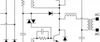
12V power supply circuit
The 14 V blocks already use 5 transistors and pulse capacitors. A four-channel type current conversion microcircuit is used. The resistor capacitance does not exceed 6.3 pF.
14V charger circuit
18 V chargers use only transition type transistors. A grid trigger is installed to normalize the maximum frequency. The current conductivity is in the region of 5.4 microns. There are 3 capacitors on the chip. A tetrode is located together with the diode bridge. Some models use chromatic resistors. Dipole transistors are sometimes used. 18V charger circuit
Manufacturing a power supply based on the battery compartment of a screwdriver
Initial data
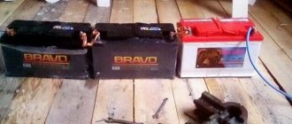
We have two Chinese cordless screwdrivers in stock. Only one of them has a battery compartment; and even that one, over the years, unfortunately, stopped holding a charge. It did not seem economically feasible to buy a new battery compartment or replace batteries due to the fact that its cost is often comparable to the cost of a new similar screwdriver.
Result of the work performed
The inside of the battery compartment has become unusable
Task
Upgrade the battery pack to obtain an easy-to-use power supply from mains voltage with low financial costs. In the end it came out to about $7, since there was a lot in stock.
PSU manufacturing
List of elements used:
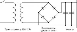
- Step-down transformer 220/12 (was available)
- Diode bridge KVRS 2510 ($1.5)
- Adjustable Voltage Stabilizer 20A ($3)
- Capacitor 10000uF/25V ($1)
- Two diodes (were available)
- Network connectors 4 pieces ($1)
- Fan 12V (was available)
- Radiator (was available)
List of necessary tools, in addition to standard ones:
- Construction hair dryer with temperature control - for extruding the desired shape of a plastic case
- Mini-drill engraver - for grinding and finishing holes for plugs
- Soldering iron 100W - for straightening plastic
- Three clamps for extrusion
Sequence of work:
Making holes for the stems
To do this, we use a powerful 100W soldering iron. Plastic melts well. We remove the remains with pliers and modify the hole to the required shape with a mini-drill with the necessary attachments.
We make holes for the remaining two plugs in the same way.
Transformer installation
Due to the fact that the available transformer did not fit slightly (by 4 mm) into the battery compartment, it was decided to enlarge the latter by squeezing out the plastic when heated.
ABS plastic softens noticeably after 100 degrees Celsius. We secure the block together with the transformer using three clamps and remnants of chipboard. Gradually heat up the plastic with a construction hairdryer and tighten the handles of the clamps in parallel. We achieve the desired degree of extrusion and let the plastic cool. After this we remove the load.
As a result, we obtain an acceptable block shape.
Installation and testing of “electronic filling”
The connection diagram of the elements is quite simple.
Transformer - diode bridge - voltage stabilizer - capacitor.
A radiator was attached to the transistor to remove heat. Additionally, a fan is connected to improve air circulation. I also subsequently made a dozen holes in the case to improve air circulation. The capacitor was placed in the vertical part of the block. The output voltage was set to 14.4V
Plugs and reverse polarity protection in screwdriver housings
A diode was added to the wiring inside the screwdrivers to protect against over-reversal.
Finish photos
Result
Supply voltage at the power supply output without load = 14.4V.
At idle, when one screwdriver is connected = 12.8V (current 1.3A) In operating mode, the current approaches 3A. At idle when two screwdrivers are connected = 10.2V
To use the power supply, three power cables were soldered in length: 2.7 m, 4.9 m, 10.4 m. The voltage drop when using them, respectively: 0.2V - 0.3V - 0.9V (at idle, i.e. e. current 1.3A)
The temperature regime when operating two screwdrivers in XX mode for three minutes is satisfactory. The temperature rose to 55 degrees Celsius.
Video (photo collage) showing the manufacturing process:
Video showing the process of demonstrating the work:
PS There is a suspicion that there are too many photos in the post. If this is the case, I apologize. The first post - it’s not entirely clear to what extent everything needs to be presented and shown.
DIY power supply for a screwdriver
The standard charger uses a three-channel chip. Depending on the voltage, a different number of transistors are placed on it, for example, 4 transistors are installed in a 12-volt charger. To reduce the negative effects of clock frequency, capacitors are installed in the blocks. They are of impulse or transient type. To minimize the consequences of electrical network overloads, thyristors are used in chargers.
Standard screwdriver charging circuit
This is important: in different models, not only different numbers of transistors are installed - they differ significantly in their capacity.
Power supply for a screwdriver from an energy-saving lamp In order to make a UPS from an energy-saving lamp, it is necessary to slightly change the electronic choke contained in each lamp by placing a jumper, and then connect it to a pulse transformer and rectifier. For low-power power supplies (from 3.7 V to 20 watts), you can do without a transformer. To do this, you simply need to add a few turns of semiconductor to the magnetic circuit of the inductor located in the lamp ballast, if there is room for this. The winding can be done directly over the factory one. To do this, it is better to use a wire with fluoroplastic insulation.
Power supply for screwdriver from charger
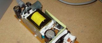
One of the cheapest ways to make a power bank is to use a regular smartphone charger. Every home now has two or more of them, and if you don’t have any extra, you can buy them for 50–100 rubles.
This is what the insides of a smartphone charger look like
The charging modification is carried out in the following sequence:
• Using a small diameter enamelled conductor, one turn of the winding must be added. After that, turn on the charger and connect the screwdriver to the battery. Using an oscilloscope, we measure the amplitude of the pulses and determine the voltage created by one turn of the additional winding. • Unsolder the USB connector, remove the test turn and wind the required number of turns until the required voltage is obtained. The new winding is soldered to the factory one in series. • We replace the standard capacitor and zener diode with new ones that correspond to the required voltage.
DIY switching power supply for a screwdriver
A suitable microcircuit is selected for the pulse unit, and assembly is carried out in the following sequence:
• Diode bridges and a thermistor are placed at the input. • Two capacitors are installed. • Drivers are used to synchronize the operation of the gates of field-effect transistors. • When installing transistors, the flanges are not short-circuited. They are attached to the radiator using insulating washers and gaskets. • Diodes are installed at the output.
Power supply for a screwdriver made from an electronic transformer
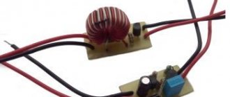
To adapt the transformer to the charger of your tool, it needs to be modified. To do this, you need to connect a capacitor at the output of the rectifier bridge. Capacitance is determined as follows - 1 µF per 1 W. The capacitor voltage must be at least 400 V. A thermistor must be installed in the gap of one network cable to limit the inrush current. A diode bridge is installed to rectify voltage with a frequency of 30 kHz. For normal operation of the device, a smooth start is required. Throttle L1 copes with this perfectly.
DiyTronic
One of the crafts required power of about 12-15 volts. Like many people, you probably have a bunch of power supplies from old mobile phones lying around at home. But they are all usually 5 volt. I decided to modify one of these blocks and increase its voltage to the required one.
As a rule, all modern power supplies are switching, which, on the one hand, reduces their size, but on the other hand, this is achieved by some complication of the circuit design.
I didn’t take pictures of this power supply in its original case, but it probably doesn’t matter - it’s a regular black plastic case with a plug.
Below the board looks like this
And this is the installation view
A classic switching power supply is visible to the naked eye.
The first thing that came to mind was to increase the voltage in the regulator feedback circuit. To do this, at a minimum, it was necessary to find a divider on the board. Here he is.
The lower 4.9 kOhm divider resistor was replaced with a 10 kOhm trimmer. The installation is certainly unsightly, but it’s a temporary structure and copes with the required task quite well.
It didn’t work - the voltage was raised to a maximum of 8 volts. At the same time, the power supply began to beep desperately, which seemed to hint to us that the operating mode was far from optimal.
I considered further violence pointless and decided to dig deeper.
The transformer was removed from the board. The hope for painless removal of the core was not justified - only one half came out easily, and the second was glued to the coil with windings with some kind of compound and I did not dare to tear it off, because I was afraid of damaging the fragile core. Nevertheless, even in this form it was possible to quite easily remove the insulation of the windings and expose the first winding. As it turned out, it was a control winding, and I needed a secondary one.
I had to wind up this winding, after which the secondary winding was exposed, which consisted of 10 turns of copper wire with a diameter of 0.6 mm, wound in 2 cores.
Because I needed to increase the voltage by about 2 times, so I wound up another 12 turns. Although, as I thought later, it was possible not to finish winding anything and simply divide the winding wires and thus double their number. Our power still hasn’t changed and is limited by the cross-section of the transformer core, and by increasing the voltage by 2 times, the maximum current correspondingly decreased by 2 times and it would be possible to get by with a wire of half the cross-section. But as they say, “a good thought comes later.”
In total, after winding the required number of turns and returning the control winding back, the following design was obtained.
Well, then the transformer was returned to the board.
Using a trimmer resistor on the regulator it was easy to get the required 12 volts. The bonus was the disappearance of even that small whistle that this power supply had before the modification. Well, then everything is simple - the trimmer was replaced with a constant resistor and everything finally turned into candy.
This is how you can use old trash in your crafts.
PS: In fact, it was made back in 2015 - I just got around to finishing it :)
DIY screwdriver straightener
A rectifier is needed to convert AC to DC. It operates using semiconductor diodes, which act as converters. An oscilloscope is used to analyze the operation of the device. The main thing in the manufacture of a rectifier is the correct choice of diodes. For use in a power supply, elements with reverse current ratings of up to 10 amperes are suitable. The number of diodes is 4, and they should be installed as a bridge type. If the circuit is used on one semiconductor, the useful effect of the unit is halved.
This is important: it is prohibited to work with live electrical components. Before performing any manipulations, you need to make sure that the device is disconnected from the network.
Installation
The adjustment consisted in the fact that it was necessary to remove the main button and the “boom” located on it with the screw rod located inside for pressing the power supply key to the converter from the 1.2 V battery, and turn the screw half a turn counterclockwise, that is, unscrew – increase the length of the rod. Now the converter turned on a moment earlier and, accordingly, the multimeter turned on as normal (from the first press).
And to confirm my IMHO that replacing the battery located on the outside of the body of a measuring device is much more attractive than charging it when located inside, I invite you to watch a short video demonstrating this process. Please note that the replacement itself lasts 15 seconds (in working order it is 5).
Transformer block for powering a screwdriver
Transformer power supplies are devices that contain a transformer that reduces the input voltage. In addition to it, such blocks contain a diode rectifier and a filter capacitor. The capacitor smoothes out the output voltage ripple. In fact, the transformer produces the same type of voltage as in a 220-volt network, or rather, sinusoidal. When operating from uninterrupted sources, its shape may be completely non-sinusoidal. The shape of the rectified voltage is not constant over time, so it is necessary to install an element that maintains a constant output voltage, which is done on a smoothing capacitor.
Advantages of transformer blocks:
• Simplicity and reliability. • The components are easy to find commercially. • No parts that create radio wave interference.
Stabilizer circuit for APL1117
The lay file contains two printed circuit boards, one for stabilizers with adjustable output voltage, the other for fixed ones.
In the photo of the signet, the adjusting resistor R1 is 120 Ohm, the output is 5 V, at 150 Ohm - 4.2 V. The datasheet for APL1117 is here.
And here, for general development, is detailed information about this series. APL1117 are linear voltage regulators of positive polarity with low saturation voltage, manufactured in SOT-223 and ID-Pack packages. Available in fixed voltages 1.2, 1.5, 1.8, 2.5, 2.85, 3.3, 5.0 volts and adjustable 1.25 V.
The output current of the microcircuits is up to 1 A, the maximum power dissipation is 0.8 W for microcircuits in the SOT-223 package and 1.5 W for those in the D-Pack package. There is a protection system for temperature and power dissipation. A strip of copper foil of a printed circuit board or a small plate can be used as a radiator. The microcircuit is attached to the heat sink by soldering a heat-conducting flange or glued to the body and flange using heat-conducting glue.
The use of microcircuits of these series provides increased output voltage stability (up to 1%), low current and voltage instability coefficients (less than 10 mV), higher efficiency than conventional 78LХХ, which allows reducing input supply voltages. This is especially true when powered by batteries.
If a more powerful stabilizer is required that produces a current of 2-3 A, then the typical circuit must be changed by adding transistor VT1 and resistor R1.
Power supply for screwdriver
In order to power a screwdriver with your own hands from a household electrical outlet, you will need a failed battery, a battery charger, stranded wire, electrical tape, solder, a soldering iron and acid. First of all, you need to solder an electrical wire with a plug to the contacts of the charger. Since the block uses brass terminals and the wire has copper strands, in order to solder them, you must use acid as a connector. The functioning of the entire device directly depends on the quality of this connection. At the second stage, work is carried out with a failed tool battery. The battery should be disassembled and the internal parts removed. During this operation, you need to use personal protective equipment, and it is recommended not to throw the internal filling into household waste, but to dispose of it in a place safe for people. At the final stage, it is necessary to solder the charger wires to the battery terminals, which are located in the inside of the case.
When making a homemade power supply for a screwdriver, you must carefully observe safety precautions when working with electricity. Before starting work, you need to carefully weigh the pros and cons (how much time it will take, what the cost of materials and spare parts will be), sometimes it will be easier and cheaper to take the charger to a specialized workshop or purchase a new unit.
Universal blocks
Making a universal power supply for an 18V screwdriver with your own hands is quite simple. First of all, it is recommended to prepare a 5 pF output capacitor. An additional resistor is required. Converters for blocks are used with a negative direction. They can be used in a DC circuit and are well suited for a 220 V network. Experts advise installing comparators with beam adapters. They are highly resistant to impulse noise. It should also be noted that filters for the capacitor are selected with an electrode trigger. At the end of the work, the block is checked for resistance. When assembled correctly, the modification should produce no more than 40 ohms.