Ohm's law
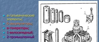
After Faraday's discovery of electromagnetic induction in 1831, the first direct and then alternating current generators appeared. The advantage of the latter is that alternating current is transmitted to the consumer with less losses. The value of current in an AC circuit is directly proportional to the voltage in the circuit and inversely proportional to the impedance of the circuit.
Ohm's law for a complete circuit - definition and formula
Ohm's Law shows the relationship between voltage (V), current (I) and resistance (R). This can be written in three different ways:
V = I × R
or
I = V/R
or
R = V/I
Where:
- V – voltage in volts (V);
- I – current strength in amperes (A);
- R – resistance in ohms (Ohm);
For most circuits, amps are too large and ohms too small. Therefore, milliamps and kilo-ohms can be substituted into the formula. If the current is set in milliamps (mA), then the resistance must be in kilo-ohms (kOhm) and vice versa. Voltage is always in volts.
Modifications of Ohm's law.
To make it easier to remember the three different versions of the definition of Ohm’s Law, you can use the “VIR triangle”.
- Georg Simon OhmIf we need to calculate the voltage, we close V with our finger. We are left with I and R. They are at the same level, which means we put a multiplication sign between them. It turns out: V = I × R.
- If we calculate the current, we close I with our finger. We are left with V above R. This means the voltage is divided by the resistance: I = V/R.
- We proceed in a similar way when calculating resistance. We close R. What remains is V over I. This means: R = V/I.
Ohm's law definition: Current is directly proportional to voltage and inversely proportional to resistance. There is also a special case - Ohm's Law for a section of a circuit - the current strength in a section of a circuit is directly proportional to the voltage at the ends of the section and inversely proportional to the resistance of this section.
Content
To describe the process of electric current flowing in a circuit, we already have three characteristics: current strength, voltage and resistance.
We found out that some of them are related. The current strength depends on the voltage . These quantities are directly proportional to each other. The number of times the voltage at the ends of the conductor increases, the same number of times the current in it increases. We changed the conductor in these experiments, the resistance remained constant.
Next, we learned that the current strength also depends on the electrical resistance of the conductor. The ammeter readings changed when different conductors were connected to the circuit. The voltage remained constant in these conductors.
But we have not yet established how these three quantities are related to each other at once. In this lesson we will experimentally prove this connection and get acquainted with Ohm's law for a section of a chain.
Ohm's law - the basis of electrical engineering
This basic equation, used to study electrical circuits, was obtained experimentally by Georg Simon Ohm. He was born in Erlangen Germany in 1787 and entered the university of that city in 1805, where he received his doctorate. Georg taught mathematics in schools and conducted physics experiments in the school physics laboratory, trying to understand the principles of electromagnetism.
In 1827, he published papers describing a mathematical model of how circuits conduct heat in the works of Fourier. Ohm obtained experimental data on the basis of which he was able to formulate his law for the first time on January 8, 1826. He established that the potential difference between two points in a circuit is equal to the product of the current between them and the total resistance of all electrical devices. The greater the battery's voltage, or its total electrical potential difference, the greater its current will be. Likewise, with more resistance it will be less.
But his research did not find proper understanding and Georg left his work in Cologne. Only in 1833 did he receive a professorship in Nuremberg. Ohm's findings served as a catalyst for the latest research in electricity. In 1841, the scientist was awarded the Copley Medal, and in 1872, the "Ohm" was adopted as a unit of resistance in electrical circuits.
Ohm's Law for a complete electrical circuit describes the flow of current through conductive metals when different voltage levels are applied. Some materials, such as electrical wires, have little resistance to current flow—this type of material is called a conductor.
Important! In other cases, the material may prevent current flow but still allow it to be used. In electrical circuits, these components are often called resistors. There are materials that practically do not allow current to pass through, they are called insulators.
Ohm's law formula
Ohm's First Law states that the potential difference between two points of a resistor is proportional to the current. Moreover, according to this law, the relationship between potential and current is always constant for ohmic resistors.
V = RI, where:
V—voltage/electric potential (V);
R—electrical resistance (ohm);
I - electric current.
Formula
In it, U is a scalar quantity and is measured in (B). The difference in electrical potential between two points in a circuit indicates the presence of electrical resistance. When I passes through a resistive element R, a drop in electrical potential occurs. This difference occurs due to energy dissipation called the Joule effect. I measures the flow of charges through the body in (A) and is directly proportional to the resistance of the wire.
Ohm's second law states that electrical resistance R is a property of a body that regulates the permeability of I. This property depends on the geometric factors of the body, such as the length or cross-sectional area of the section and on the value R caused. Its amount depends solely on the material of the section.
R= ρ*L/S, where:
R—electrical resistance (Ohm);
ρ—electrical resistivity of the wire (Ohm.m);
L is the length of the conductor (m);
S is the cross-sectional area of the wire (m²).
An ohmic resistor is any body capable of presenting a constant resistance for a given voltage range. The voltage versus current plot for ohmic resistors is linear. A resistor can be considered ohmic in the range in which its potential increases linearly with increasing I.
Resistance can be understood as the slope of the line given by the tangent of the angle. As is known, tangent is defined as the ratio between the opposite and adjacent sides, and, in the case where the resistance is ohmic, can be calculated by the formula: R = U / I.
Triangle
To help remember the formula, you can use a triangle with one side horizontal and the apex at the top, like a pyramid. This is sometimes called Ohm's triangle law. In its upper corner is the letter V, in the left corner is the letter I, and in the lower right corner is R.
Note! To use a triangle, cover the unknown parameter and then calculate it from the other two. If they are on the same line they are multiplied, but if one is above the other they should be separated. In other words, if I needs to be calculated, the voltage is divided by the resistance, that is, V/R.
Where and when can Ohm's law be applied?
Ohm's law in the form mentioned is valid within fairly wide limits for metals. It is carried out until the metal begins to melt. A less wide range of applications is in solutions (melts) of electrolytes and in highly ionized gases (plasma).
When working with electrical circuits, sometimes you need to determine the voltage drop across a certain element. If it is a resistor with a known resistance value (it is marked on the case), and the current passing through it is also known, you can find out the voltage using Ohm’s formula without connecting a voltmeter.
Electrical resistance
Electrical resistance is a physical quantity that characterizes the resistance of a conductor or electrical circuit to electric current.
Electrical resistance is defined as the proportionality coefficient $R$ between voltage $U$ and direct current $I$ in Ohm's law for a section of a circuit.
The unit of resistance is called ohm (Ohm) in honor of the German scientist G. Ohm, who introduced this concept into physics. One ohm ($1$ Ohm) is the resistance of a conductor in which, at a voltage of $1$ V, the current strength is equal to $1$ A.
Resistivity
The resistance of a homogeneous conductor of constant cross-section depends on the material of the conductor, its length $l$ and cross-section $S$ and can be determined by the formula:
How to find resistance, voltage
Knowing the formula of Ohm's law for a section of a circuit, we can calculate the voltage and resistance. Voltage is found as the product of current and resistance.
Formula for voltage and resistance according to Ohm's law
Resistance can be found by dividing voltage by current. It's really not difficult. If we know that a certain voltage was applied to a section of the circuit and we know what the current was, we can calculate the resistance. To do this, divide the voltage by the current. We get exactly the resistance value of this piece of circuit.
On the other hand, if we know the resistance and the current that should be there, we can calculate the voltage. You just need to multiply the current and resistance. This will give the voltage that must be applied to this section of the circuit to obtain the required current.
Capacitance
Let us assume that a capacitor of capacitance $C$ is included in a section of the circuit, and $R=0$ and $L=0$. We will consider the current strength ($I$) to be positive if it has the direction indicated in Fig. 2. Let the charge on the capacitor be equal to $q$.
Figure 2.
We can use the following relationships:
If $I(t)$ is defined by equation (1), then the charge is expressed as:
where $q_0$ is an arbitrary constant charge of the capacitor, which is not associated with current fluctuations, so we can assume that $q_0=0.$ We obtain the voltage equal to:
Formula (6) shows that voltage fluctuations on a capacitor lag behind current fluctuations in phase by $frac{pi }{2}.$ The voltage amplitude across the capacitor is equal to:
The quantity $X_C=frac{1}{omega C}$ is called reactive capacitance (capacitance, apparent resistance of a capacitance). If the current is constant, then $X_C=infty $. This means that no direct current flows through the capacitor. From the definition of capacitance it is clear that at high oscillation frequencies, small capacitances are small resistances to alternating current.
Do you need advice on your academic work? Ask your teacher a question and get an answer in 15 minutes! Ask a Question
Voltage, resistance, current - how are these terms related?
To further understand the process, let's take another look at our water tower:
In the picture we see a tower with automatic water level adjustment. That is, no matter how much water we use from the tower, the water pump in the booth will always supply water to the required level and then turn off. If we translate it into electronics language, we get that the “voltage” at the bottom of the water tower is constant.
Case N1
But then a crisis came and your neighbor became unable to pay high tariffs for water, and so one night he made a large diameter tap right at the foot of the water tower.
As soon as I drilled the hole, water rushed out of the tower in a rapid stream. What can be said in this case? The strength of the flow through the hole turned out to be decent, since our tower is filled to capacity with water, and the water level is not going to fall, since we immediately connected a powerful pump for automatically supplying water from an artesian well. If there were only a couple of buckets of water in the tower, then the flow of water would be very weak. Everything seems to be clear with this.
Case N2
Let's say your neighbor is a major. He rides a Lada-Vesta and goes on vacation to Crimea). For him, paying 100 rubles a month for clean water is the same as going to a tavern with friends. But while he was sunbathing in Crimea, his children, whom he had left with his mother-in-law, snuck into the garage and found a screwdriver and a set of drills. Well, as often happens, they suddenly wanted to drill something. But then my mother-in-law suddenly came and shouted: “Well, come on... from daddy’s garage!” scattered the children, who still managed to grab a screwdriver and drills with them. And then a lonely tower caught their eye... and everything happened as in the first scenario... They drilled a thin hole right at the foot of the water tower.
What can be said in this case? The pressure is the same as in the first case, since the water level in the tower is the same. Now the final question.
In what case, by analogy with electronics, will we have more current?
So, we remember, current is the number of electrons that passes through the cross section of a conductor in a certain time. Basically in a second. So in what case will the number of water molecules flowing out of the tower per second be greater? In the first or second case? Of course, in the first one, since the neighbor did not waste time on trifles and made a hole of a large diameter, and the newcomers spent half a day drilling a hole with a small diameter, since they did not find a large drill. In this case, the strength of the water flow depends on the diameter of the hole . By analogy with hydraulics, the current strength, it turns out, depends on the diameter of the wiring. The thinner the wires, the less current can flow through it, otherwise the wires will burn out. We already dealt with this in the previous article. Well, here we are gradually approaching such a concept in electronics as resistance .
Inductive reactance
Let a section of the circuit have only inductance (Fig. 3). We will assume $I>0$ if the current is directed from $a$ to $b$.
Figure 3.
If a current flows in the coil, then a self-inductive emf appears in the inductance, therefore, Ohm’s law will take the form:
By condition $R=0. The mathcal E$ of self-induction can be expressed as:
From expressions (8), (9) it follows that:
The voltage amplitude in this case is equal to:
where $X_L is $inductive reactance (apparent inductive resistance).
Ohm's law for a circuit
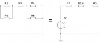
Ohm’s law for a section of a circuit can, of course, be described by the formula known from a school physics course: I=U/R, but I think it’s worth making some changes and clarifications. Let's take a closed electrical circuit and consider its section between points 1-2. For simplicity, I took a section of the electrical circuit that did not contain sources of emf (E).
So, Ohm's law for the section of the circuit under consideration has the form:
φ1-φ2=I*R, where
- I – current flowing through a section of the circuit.
- R is the resistance of this section.
- φ1-φ2 – potential difference between points 1-2.
If we take into account that the potential difference is voltage, then we come to the derivative formula of Ohm's law, which is given at the beginning of the page: U=I*R. This is the formula of Ohm's law for the passive section of the circuit (containing no sources of electricity).
In an unbranched electrical circuit (Fig. 2), the current strength in all sections is the same, and the voltage in any section is determined by its resistance:
- U1=I*R1
- U2=I*R2
- Un=I*Rn
- U=I*(R1+R2+…+Rn
From here you can obtain formulas that are useful in practical calculations. For example:
U=U1+U2+…+Un or U1/U2/…/Un=R1/R2/…/Rn
The calculation of complex (branched) circuits is carried out using Kirchhoff's laws.
Ohm's law for a section of a circuit.
For EMF
Before considering Ohm's law for a complete (closed) circuit, I will give a sign rule for EMF, which states: If inside the EMF source the current flows from the cathode (-) to the anode (+) (the direction of the field strength of external forces coincides with the direction of the current in the circuit, then the EMF of such a source is considered positive, otherwise the EMF is considered negative.
A practical application of this rule is the possibility of bringing several sources of EMF in a circuit to one with the value E=E1+E2+…+En, naturally, taking into account the signs determined by the above rule. For example (Fig. 3.3) E=E1+E2-E3. In the absence of a back-to-back source E3 (in practice this almost never happens), we have a widespread serial connection of batteries, in which their voltages are summed.
For a complete chain
Ohm's law for a complete circuit - it can also be called Ohm's law for a closed circuit, has the form I=E/(R+r). The above formula for Ohm's law contains the notation r, which has not yet been mentioned. This is the internal resistance of the EMF source. It is quite small, in most cases it can be neglected in practical calculations (provided that R>>r - the circuit resistance is much greater than the internal resistance of the source). However, when they are comparable, the value of r cannot be neglected.
As an option, we can consider the case in which R=0 (short circuit). Then the given formula of Ohm's law for the complete circuit will take the form: I=E/r, that is, the value of the internal resistance will determine the short-circuit current. This situation may well be real. Ohm's law is discussed here quite briefly, but the formulas given are sufficient to carry out most calculations, examples of which, as other materials are posted, I will give.
A complete circuit is made up of a section (sections), as well as a source of EMF. That is, in fact, the internal resistance of the EMF source is added to the existing resistive component of the circuit section. Therefore, it is logical to slightly change the above formula:
I = U / (R + r)
Of course, the value of the internal resistance of the EMF in Ohm’s law for a complete electrical circuit can be considered negligible, although this resistance value largely depends on the structure of the EMF source. However, when calculating complex electronic circuits, electrical circuits with many conductors, the presence of additional resistance is an important factor.
Both for a section of a circuit and for a complete circuit, the natural moment should be taken into account - the use of constant or variable current. If the points noted above, characteristic of Ohm’s law, were considered from the point of view of using direct current, accordingly with alternating current everything looks somewhat different.
Original and modern formulation
This seemingly simple law was formulated by the German physicist Georg Ohm in 1826. He published the corresponding scientific article the following year.
It is interesting to note that the appearance of this work did not cause a stir. The scientific community appreciated Ohm's discovery only after the publication of works by the physicist Poulier of similar content in 1830. In 1833 Ohm received his doctorate from the University of Nuremberg. In 1872, the unit of resistance became known as the Ohm. In its simplest form, the law for a section of a chain sounds like this:
The law is empirical in nature, since it expresses a generalized analysis of a large amount of experimental data.
Now the formula for Ohm's law for a complete electrical circuit is as follows:
I = ℰ / (R+r).
Here:
- ℰ — EMF of the voltage source, V;
- I is the current strength in the circuit, A.
- R is the total resistance of all external elements of the circuit, Ohm;
- r is the internal resistance of the voltage source, Ohm.
Ohm's law for a complete circuit takes into account the total resistance, which is the sum of the circuit resistance R and the internal resistance of the current source r.
Georg Ohm originally formulated it differently. Ohm's law for a closed circuit looked like this:
X = a / ( b + l ), where
- a is a quantity characterizing the current source. Now they say that this is the electromotive force of the current source;
- b represents a property of the electrical installation, which is now considered as the internal resistance of the current source;
- l is a value that depends on the length of the wires used (in modern terms, it corresponds to the resistance of the electrical circuit).
As you can see, Ohm's law, applied to a complete electrical circuit, has the same formulation in both versions.
Ohm's law in differential form is also applied. In this case, very small quantities are considered. But this allows the use of integral and differential calculus for complex cases.
Ohm's law for alternating current
If there is inductance or capacitance in an AC circuit, its reactance must be taken into account. In this case, the entry for Ohm's Law will look like:
I = U/Z
Here Z is the total (complex) resistance of the circuit - impedance. It includes active R and reactive X components. Reactance depends on the ratings of the reactive elements, on the frequency and shape of the current in the circuit. You can learn more about complex resistance on the impedance page.
Ohm's law for a closed circuit
If an external circuit with resistance R is connected to the power source, current will flow in the circuit taking into account the internal resistance of the source:
I – Current strength in the circuit.
– Electromotive force (EMF) – the magnitude of the power source voltage independent of the external circuit (without load). Characterized by the potential energy of the source. r – Internal resistance of the power supply.
For electromotive force, the external resistance R and internal r are connected in series, which means the magnitude of the current in the circuit is determined by the value of the emf and the sum of the resistances: I = /(R+r) .
The voltage at the terminals of the external circuit will be determined based on the current and resistance R by the relationship that has already been discussed above: U = IR.
Voltage U, when connecting a load R, will always be less than the EMF by the value of the product I*r, which is called the voltage drop across the internal resistance of the power source. We encounter this phenomenon quite often when we see partially discharged batteries or accumulators in operation.
As the discharge progresses, their internal resistance increases, therefore, the voltage drop inside the source increases, which means the external voltage U = – I*r decreases.
The lower the current and internal resistance of the source, the closer in value its EMF and the voltage at its terminals U. If the current in the circuit is zero, therefore = U. The circuit is open, the EMF of the source is equal to the voltage at its terminals.
In cases where the internal resistance of the source can be neglected (r ≈ 0), the voltage at the source terminals will be equal to the EMF (≈ U) regardless of the external circuit resistance R. Such a power source is called a voltage source.
What changes for a full chain
In the situation above, only a certain section of the circuit with some fixed resistance is considered. We assume that under certain conditions the electrons will begin to move. The reason for this movement is the same load in the picture. In real conditions, this is a current source. This could be a battery, a DC generator, a connected power supply cord, etc. When a power source is connected to a conductor, current begins to flow through it. We also know and observe this when we turn on a lamp, charge a mobile phone, etc.
The complete circuit includes a power supply
A section of the circuit has some kind of resistance. It's clear. But the power supply also has resistance. It is usually denoted with a small letter r. Since the current runs in a circle, it has to overcome the resistance of the wire and the resistance of the current source. This total resistance of the circuit and the power source is called impedance. They also say that this is complex resistance. In Ohm's formula for a complete circuit it is represented by a sum. The denominator is the sum of the circuit resistance and the internal resistance of the current source (R + r).
Everyone probably understands that it is the current source that creates the necessary conditions for the movement of electrons. All thanks to the fact that it has EMF - electromotive force. This value is usually denoted E. The greater this force, the greater the current. This also seems understandable. Therefore, the designation of EMF - the Latin letter E - is placed in the numerator. Thus, the formulation of Ohm's law for a complete circuit sounds like this:
The current strength is directly proportional to the emf of the current source and inversely proportional to the sum of the circuit resistance and the internal resistance of the current source.
It doesn’t seem too difficult, but you can try something even simpler:
- The higher the EMF of the current source, the greater the current.
- The greater the total resistance, the less current.
Nonlinear elements and circuits
Ohm's law is not a fundamental law of nature and can be applied in limited cases, for example, for most conductors. It cannot be used to calculate voltage and current in semiconductor or vacuum devices, where this dependence is not proportional and can only be determined using the current-voltage characteristic (volt-ampere characteristic). This category of elements includes all semiconductor devices (diodes, transistors, zener diodes, thyristors, varicaps, etc.) and vacuum tubes. Such elements and the circuits in which they are used are called nonlinear.
Ohm's law for a circuit section
From the school physics course, everyone is well aware of the classic interpretation of Ohm's Law: The current strength in a conductor is directly proportional to the voltage at the ends of the conductor and inversely proportional to its resistance.
I = U/R
This means that if a voltage U = 1 Volt is applied to the ends of a conductor with a resistance of R = 1 Ohm, then the magnitude of the current I in the conductor will be equal to 1/1 = 1 Ampere.
From here two more useful relationships follow: If a current of 1 Ampere flows in a conductor with a resistance of 1 Ohm, then at the ends of the conductor there is a voltage of 1 Volt (voltage drop).
U = IR
If there is a voltage of 1 Volt at the ends of the conductor and a current of 1 Ampere flows through it, then the resistance of the conductor is 1 Ohm.
R = U/I
The above formulas in this form can be applied to alternating current only if the circuit consists only of active resistance R. In addition, it should be remembered that Ohm’s Law is valid only for linear elements of the circuit.
A simple online calculator is provided for practical calculations. Ohm's law. Calculation of voltage, resistance, current, power.
Exercises
Exercise No. 1
The voltage at the terminals of the electric iron is $220 \space V$, the resistance of the heating element of the iron is $50 \space Ohm$.
What is the current in the heating element? Given: $U = 220 \space V$ $R = 50 \space Ohm$
$I — ?$
Show solution and answer
Hide
Solution:
Ohm's law for a section of a chain: $I = \frac{U}{R}$.
Let's calculate the current strength: $I = \frac{220 \space V}{50 \space Ohm} = 4.4 \space A$.
Answer: $I = 4.4 \space A$.
Exercise No. 2
The current strength in the coil of an electric lamp is $0.7 \space A$, the lamp resistance is $310 \space Ohm$.
Determine the voltage at which the lamp is located. Given: $I = 0.7 \space A$ $R = 310 \space Ohm$
$u — ?$
Show solution and answer
Hide
Solution:
Ohm's law for a section of a chain: $I = \frac{U}{R}$.
Let us express the voltage from here and calculate it: $U = IR$, $U = 0.7 \space A \cdot 310 \space Ohm = 217 \space B$.
Answer: $U = 217 \space В$.
Exercise #3
What resistance does a voltmeter designed for $150 \space V$ have if the current strength in it should not exceed $0.01 \space A$?
Given: $U_{max} = 150 \space B$ $I_{max} = 0.01 \space A$
$R — ?$
Show solution and answer
Hide
Solution:
Let's write Ohm's law for a section of the chain: $I = \frac{U}{R}$.
Let us express the resistance from here and calculate its value using the maximum values of voltage and current corresponding to the device: $R = \frac{U_{max}}{I_{max}}$, $R = \frac{150 \space V}{ 0.01 \space A} = 15 \space 000 \space Ohm = 15 \space kOhm$.
Answer: $R = 15 \space kOhm$.
Exercise #4
Determine the conductor resistance from the graph (Figure 4).
Figure 4. Graph of current in a conductor versus voltage
Let's take the data from the graph. At a voltage equal to $10 \space V$, the current strength in the conductor is equal to $2.5 \space A$. Let's write down the conditions of the problem and solve it.
Note that resistance $R$ does not depend on either current or voltage. Therefore, you can select other current and voltage values from the graph. Your answer to this problem will not change.
Given: $U = 10 \space B$ $I = 2.5 \space A$
$R — ?$
Show solution and answer
Hide
Solution:
Let's write Ohm's law for a section of the chain: $I = \frac{U}{R}$.
Let us express the resistance from here and calculate its value using the graph data: $R = \frac{U}{I}$, $R = \frac{10 \space V}{2.5 \space A} = 4 \space Ohm$.
Answer: $R = 4 \space Ohm$.
Exercise #5
Consider Figure 1 and the table of results of the experiment performed in accordance with this figure.
What will change in the figure and in the electrical circuit diagram when experiments No. 2 and No. 3, indicated in Table 1, are carried out? For experiment No. 2: another conductor will be connected in the figure, having a resistance of $2 \space Ohm$. The ammeter will show a current equal to $1 \space A$.
For experiment No. 3: nothing will change in the picture. This is an illustration of exactly this experiment (a conductor with a resistance of $4 \space Ohm$ is connected to the circuit).
The electrical circuit diagram will be the same for all three experiments, if you do not note the conductor resistance (Figure 5).
Figure 5. Electrical circuit diagram for experiments to determine the dependence of current on resistance
Exercise #6
Using instrument readings (Figure 6), determine the resistance of conductor AB.
Figure 6. Dependence of current on conductor properties
Given: $U = 4 \space B$ $I = 1 \space A$
$R — ?$
Show solution and answer
Hide
Solution:
Let's express the resistance from Ohm's law for a section of the circuit: $I = \frac{U}{R}$, $R = \frac{U}{I}$.
From the previous lesson: this conductor AB is an iron wire. Let's calculate its resistance: $R = \frac{4 \space B}{1 \space A} = 4 \space Ohm$.
Answer: $R = 4 \space Ohm$.
Scope of application
Ohm's law is not a basic law in physics, it is just a convenient dependence of some values on others, which is suitable in almost any practical situation. Therefore, it will be easier to list situations when the law may not work:
- If there is inertia of charge carriers, for example in some high-frequency electric fields;
- In superconductors;
- If the wire heats up to such an extent that the current-voltage characteristic ceases to be linear. For example, in incandescent lamps;
- In vacuum and gas radio tubes;
- In diodes and transistors.
Interesting read: instructions on how to ring a transistor.
Serial and parallel connection of elements
For elements of an electrical circuit (section of a circuit), a characteristic point is a serial or parallel connection. Accordingly, each type of connection is accompanied by a different pattern of current flow and voltage supply. In this regard, Ohm's law is also applied differently, depending on the option of including elements.
Circuit of series-connected resistive elements
In relation to a series connection (a section of a circuit with two components), the following formulation is used:
- I = I1= I2 ;
- U = U1+ U2 ;
- R = R1+ R2
This formulation clearly demonstrates that, regardless of the number of resistive components connected in series, the current flowing through a section of the circuit does not change in value. The magnitude of the voltage applied to the effective resistive components of the circuit is the sum and totals the value of the emf source.
In this case, the voltage on each individual component is equal to: Ux = I * Rx. The total resistance should be considered the sum of the values of all resistive components in the circuit.
Circuit of parallel connected resistive elements
In the case when there is a parallel connection of resistive components, the following formulation is considered fair in relation to the law of the German physicist Ohm:
- I = I1+ I2 … ;
- U = U1= U2 … ;
- 1 / R = 1 / R1+ 1 / R2 + …
Options for creating circuit sections of a “mixed” type, when parallel and serial connections are used, are not excluded. For such options, the calculation is usually carried out by initially calculating the resistive rating of the parallel connection. Then the value of the resistor connected in series is added to the result obtained.
Integral and differential forms of the law
All of the above points with calculations are applicable to conditions when conductors of, so to speak, “homogeneous” structure are used in electrical circuits. Meanwhile, in practice, one often has to deal with the construction of schematics, where the structure of the conductors changes in different sections. For example, wires of a larger cross-section or, conversely, a smaller one, made from different materials, are used.
To take into account such differences, there is a variation of the so-called “differential-integral Ohm’s law.” For an infinitesimal conductor, the current density level is calculated depending on the voltage and conductivity value.
For the differential calculation, the formula is taken: J = ό * E. For the integral calculation, accordingly, the formulation is: I * R = φ1 – φ2 + έ However, these examples are rather closer to the school of higher mathematics and are not actually used in the real practice of a simple electrician.
Current strength
Electric current is the ordered (directed) movement of charged particles. Electric current strength is a quantity ($I$) that characterizes the ordered movement of electric charges and is numerically equal to the amount of charge $∆q$ flowing through a certain surface $S$ (cross section of the conductor) per unit time:
$I={∆q}/{∆t}$
So, to find the current strength $I$, it is necessary to divide the electric charge $∆q$ that passed through the cross section of the conductor during the time $∆t$ by this time. The strength of the current depends on the charge carried by each particle, the speed of their directional movement and the cross-sectional area of the conductor.
Consider a conductor with cross-sectional area $S$. The charge of each particle is $q_0$. The volume of the conductor, limited by sections $1$ and $2$, contains $nS∆l$ particles, where $n$ is the concentration of particles. Their total charge is $q=q_{0}nS∆l$. If the particles move with an average speed $υ$, then during the time $∆t={∆l}/{υ}$ all particles contained in the volume under consideration will pass through the cross section $2$. The current strength is therefore equal to:
$I={∆q}/{∆t}={q_{0}nS∆l·υ}/{∆l}=q_{0}nυS$
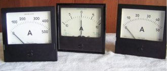
In the SI, the unit of current is the basic one and is called the ampere (A) in honor of the French scientist A. M. Ampere (1755-1836). The current strength is measured with an ammeter. The principle of the ammeter is based on the magnetic action of current. An estimate of the speed of ordered movement of electrons in a conductor, carried out using the formula for a copper conductor with a cross-sectional area of $1mm^2$, gives a very insignificant value - $∼0.1$ mm/s.
Parallel and serial connection
In electrics, elements are connected either in series - one after the other, or in parallel - this is when several inputs are connected to one point, and outputs from the same elements are connected to another.
Ohm's law for parallel and series connections
Serial connection
How does Ohm's law work for these cases? With a series connection, the current flowing through the chain of elements will be the same. The voltage of a section of a circuit with elements connected in series is calculated as the sum of the voltages in each section. How can this be explained? The flow of current through an element is the transfer of part of the charge from one part to another. That is, this is a certain job. The amount of this work is tension. This is the physical meaning of tension. If this is clear, let's move on.
Serial connection and parameters of this section of the circuit
With a series connection, the charge has to be transferred through each element in turn. And on each element this is a certain “amount” of work. And to find the amount of work on the entire section of the chain, you need to add up the work on each element. So it turns out that the total voltage is the sum of the voltages on each of the elements.
In the same way - using addition - the total resistance of a circuit section is found. How can you imagine this? Current flowing through a chain of elements consistently overcomes all resistance. One after another. That is, to find the resistance that he overcame, you need to add up the resistances. Like that. The mathematical derivation is more complex, but it is easier to understand the mechanism of action of this law.
Parallel connection
A parallel connection is when the beginnings of the conductors/elements converge at one point, and their ends are connected at another. We will try to explain the laws that are valid for compounds of this type. Let's start with the current. A current of some magnitude is supplied to the point of connection of the elements. It separates, flowing through all conductors. From here we conclude that the total current in the section is equal to the sum of the current on each of the elements: I = I1 + I2 + I3.
Now regarding the voltage. If voltage is the work done to move a charge, then the work required to move one charge will be the same on any element. That is, the voltage on each parallel-connected element will be the same. U = U1=U2=U3. It’s not as fun and visual as in the case of explaining Ohm’s law for a section of a circuit, but you can understand it.
Laws for parallel connection
For resistance, everything is a little more complicated. Let's introduce the concept of conductivity. This is a characteristic that shows how easy or difficult it is for a charge to pass through this conductor. It is clear that the lower the resistance, the easier it will be for current to pass. Therefore, conductivity - G - is calculated as the reciprocal of resistance. In the formula it looks like this: G = 1/R.
Why did we talk about conductivity? Because the total conductivity of a section with a parallel connection of elements is equal to the sum of the conductivity for each of the sections. G = G1 + G2 + G3 - easy to understand. How easy it is for current to cross this node of parallel elements depends on the conductivity of each element. So it turns out that they need to be folded.
Now we can move on to resistance. Since conductivity is the reciprocal of resistance, we can obtain the following formula: 1/R = 1/R1 + 1/R2 + 1/R3.
What does parallel and serial connection give us?
Theoretical knowledge is good, but how to apply it in practice? Elements of any type can be connected in parallel or in series. But we considered only the simplest formulas describing linear elements. Linear elements are resistances, which are also called “resistors”. So here's how you can use what you've learned:
- If there is no large resistor available, but there are several smaller ones, the required resistance can be obtained by connecting several resistors in series. As you can see, this is a useful technique.
- To extend the life of the batteries, they can be connected in parallel. In this case, according to Ohm’s law, the voltage will remain the same (you can verify this by measuring the voltage with a multimeter). And the “lifetime” of a dual battery will be significantly longer than that of two elements that replace each other. Just note: only power supplies with the same potential can be connected in parallel. That is, you cannot connect dead and new batteries. If you do connect, the battery that has a higher charge will tend to charge the less charged one. As a result, their total charge will drop to a low value.
Practical application of Ohm's law: you can create power supplies with the desired voltage and current
In general, these are the most common uses for these compounds.
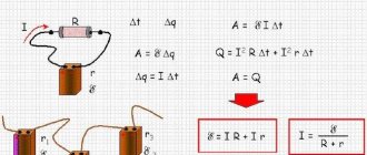
Joule-Lenz law
The Joule-Lenz law states: the amount of heat released in a conductor in a section of an electrical circuit with resistance $R$ when a direct current $I$ flows through it for a time $t$ is equal to the product of the square of the current and the resistance and time:
$Q=I^2Rt$
The law was established in 1841 by the English physicist J. P. Joule, and in 1842 it was confirmed by the precise experiments of the Russian scientist E. H. Lenz. The very phenomenon of heating a conductor when current passes through it was discovered back in 1800 by the French scientist A. Fourcroy, who managed to heat an iron spiral by passing an electric current through it.
From the Joule-Lenz law it follows that when conductors are connected in series, since the current in the circuit is the same everywhere, the maximum amount of heat will be released on the conductor with the greatest resistance. This is used in technology, for example, for spraying metals.
In a parallel connection, all conductors are under the same voltage, but the currents in them are different. From the formula ($Q=I^2Rt$) it follows that, since, according to Ohm’s law, $I={U}/{R}$, then
$Q={U^2t}/{R}$
Therefore, more heat will be generated on a conductor with less resistance.
If in the formula ($A=IUt$) we express $U$ in terms of $IR$, using Ohm's law, we obtain the Joule-Lenz law. This once again confirms the fact that the work of the current is spent on heat generation at the active resistance in the circuit.
Meaning of Ohm's Law
Ohm's law determines the current strength in an electrical circuit at a given voltage and known resistance. It allows you to calculate the thermal, chemical and magnetic effects of current, as they depend on the strength of the current.
Ohm's Law is extremely useful in engineering (electronic/electrical) because it deals with three basic electrical quantities: current, voltage and resistance. It shows how these three quantities are interdependent at the macroscopic level.
If it were possible to characterize Ohm's law in simple words, then it would clearly look like this:
It follows from Ohm's law that it is dangerous to close a conventional lighting network with a conductor of low resistance. The current will be so strong that it can have serious consequences.
Problem 1.1
Calculate the current passing through a copper wire 100 m long, with a cross-sectional area of 0.5 mm2, if a voltage of 12 V is applied to the ends of the wire.
The task is simple; it consists in finding the resistance of a copper wire and then calculating the current strength using the Ohm's law formula for a section of the circuit. Let's get started.
Resistance and current
This means that the diameter of the hole matters a lot to the flow of fluid. The diameter of the hole in this case is the cross-section of the pipe, right? What will happen if we insert a hundred-meter pipe into the hole we drilled in the tower? I think it will be no secret to anyone that the flow of water coming out of the pipe will be less than directly from the tower opening. Why is this happening? The point is that water rubs against the walls of the pipe. That is, the walls of the pipe create resistance to the flow of water. Therefore, the longer the pipe, the greater the resistance to flow at the pipe outlet. And the greater the resistance, the less the pressure, we read it as voltage.
Also in electronics. Wires of the same diameter and made of the same material, but of different lengths, also have different resistances. A long wire will have more resistance than a short wire.
And one more nuance.
Which pipe is better for water to flow through? The one with poop stuck on it, or the clean one?
Of course, water will flow better through a clean pipe than through a dirty one. The same can be said about wires. Different metals have different conductivities.
Now let's summarize all of the above. It turns out that the resistance of the wiring depends on the cross-sectional area, its length, and also on the material from which it is made. All this formula will look like this:
A radio element resistor is used as resistance in electronics:
When electric current passes through a resistor, the current in the circuit begins to change. For ease of understanding, from a hydraulic point of view, the resistor can be depicted as a valve damper:
which changes its resistance depending on how much the damper is open.
Let's say we have pressure in the pipe, but the damper is completely closed. In this case, the flow of water stands still and the water does not flow anywhere. Therefore, the flow force in the pipe is zero. But as soon as we open the valve a little, we will experience water movement, which in turn will cause a flow of water. It is not difficult to guess that the more we open the valve, the stronger the flow of water becomes. When the damper is fully open, the water flow will be maximum.
Now let's look at another nuance. With the valve fully closed, we had full water pressure applied to the damper. There is no water flow. This is understandable, the valve does not allow water to flow, although the water is under pressure.
But what happens when we open the damper a little? Will the pressure on the valve itself decrease? Of course. Since the damper resistance area has become smaller. But the most interesting thing also began. There was a movement of water.
What if we open the tap completely and set the valve in this position? What pressure will the flow of water exert on its area?
I think, in an ideal case, we can say that there is none. In a real case, very, very weak pressure will be exerted on the damper area, since it is located parallel to the water flow.
And now another interesting question: what else will the pressure on the damper depend on? From the power of the flow! What is the force of the flow? From pressure! The stronger the water flow, the greater the pressure on the valve. But again, in order for there to be a flow of water, the damper must be open at least halfway, as in this figure:
Classic hydraulics, nothing complicated in theory. Now let's apply all this to electronics.
Let's start with the basics. Pipe - wiring. Voltage is the pressure in the system. Water molecules are electrons. Current strength is the number of water molecules that passed through the cross section of the pipe in 1 second. AND... SHUTTER! What is she doing? Provides RESISTANCE to water flow. This means that the damper is resistance. A completely closed damper means a very high resistance (one might say a break), the damper is parallel to the flow of water, very little resistance (one might say 0 Ohm).
But now ATTENTION! What is the area of the damper on which pressure is applied? Voltage! And when is the pressure on the valve highest? Then when it is completely closed ;-). A fully closed damper is a resistance with an infinitely large resistance value. And when is the minimum pressure applied to the valve? Then when it stands parallel to the flow of water ;-). That is, in this case its resistance is almost 0 Ohm.
It turns out that in electronics, as in hydraulics, the VOLTAGE DROPS across the resistance. The higher the resistance value, the more the voltage drops across this resistance, and vice versa.
And now another important point. What does the pressure on the valve depend on? On the pressure in the system, as well as on the flow force. But again, in order to cause the force of the flow, the damper must be placed as parallel to the flow of water as possible. That is, we reduce the resistance and at the same time increase the current. It turns out that all these three parameters, voltage, current and resistance, are interconnected.