How to measure high voltage with a multimeter
The main difficulty in measuring high voltage with a multimeter is creating a divider circuit.
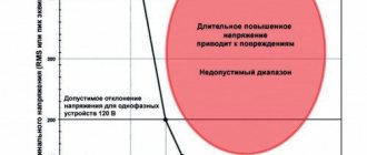
Typically, certified household devices provide the ability to measure voltages up to 1-2 thousand volts. And this is justified, because working with higher potentials is dangerous to health, and the need for such manipulations at home is extremely unlikely.
In what cases can measuring high voltages be useful?
If we exclude situations of gaining new experience, self-development, etc., then the most likely reasons are the following:
- Checking the performance of specific power units, for example: High voltage at the TDKS anode (nowadays the use of picture tubes in TVs is very rare);
- Filament voltage in transformers for microwave ovens;
- And so on.
In the last two cases, you should use only special kilo-ohmmeters that correspond to the permissible measurement parameters.
In everyday life, special accuracy is not important, and the current strength of step-up transformers is often small.
Therefore, the use of a divider for one-time measurements is more than justified.
How to make a divisor
The basic principle of construction is the creation of a shoulder from two resistances, the nominal values of which are correlated multiples.
For example: 20 MOhm and 2 kOhm. The ratio is 1:10,000.
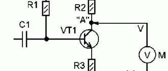
The circuit diagram of the divider can be presented as follows.
Rice. 1. Schematic diagram of the divider
In this case, the voltage U2 will be calculated as U·R2/(R1+R2).
That is, with a ratio of R1:R2 as 1:1000, it turns out U1 = U·1/(1000+1) = U/1001.
At a ratio of 1:10000 – U/10001 and so on.
In this case, the unit at the end can simply be neglected, since the resistors themselves may have deviations in their nominal values, and this will have little effect on the measurement errors at such potentials.
Thus, it is enough to assemble a divider from available resistances that will correlate with the desired coefficient.
Resistors do not have to be in one copy. You can assemble them in series or in parallel, but then you should definitely calculate the final nominal value, and for additional confidence, measure the resistance after assembly.
One of the divider options with sequential assembly
Rice. 2. One of the divider options with sequential assembly
The higher the accuracy of the resistors, the better. But even a tolerance of 1-3% is not a problem here.
Security measures
Working with high voltages is always dangerous.
To prevent overheating of resistors, you should use models designed to work with high voltages (for example, 30-40 kV, KEV or MLT-2 models) and with a high heat dissipation coefficient (2W and above, and preferably 8W).
All connections from component elements should be made in such a way as to prevent the occurrence of breakdown current. For example, place the resistors in series without intersecting or overlapping in a plane, place them in a glass flask or inside another material with high electrical density (polystyrene, plexiglass, textolite, etc.).
No less caution should be exercised during the measurement process itself:
- The device under test must be disconnected when connecting the divider and measuring device.
- Please note that charge can accumulate in picture tubes (at the anode).
- After measurements, the device under test should be de-energized again.
How to take measurements
The divider is connected to the measured section of the circuit. In the example above, these are contacts X1 and X2.
The measuring device is connected with one probe to the COM contact (aka X2). And the second - to terminal V (at the division point).
The resulting numerical result is multiplied by the divisor coefficient (it will depend on the denominations used and is calculated individually).
Author: RadioRadar
TI chips with built-in shunt for current measurement
Texas Instruments 's extensive product portfolio now includes current meters with a built-in shunt. We present two types of such microcircuits, each of which is designed to solve different specific problems. Using a built-in shunt, the INA250 and INA260 ICs allow bidirectional load current sensing from the power rail or ground rail.
Integration of a precision resistor for current control into the microcircuits provides high measurement accuracy comparable to calibrated ones and minimal dependence of characteristics on temperature fluctuations. In addition, both chips use an optimized 4-point current sense shunt connection (Kelvin circuit).
INA250
The INA250 is a current-sensing amplifier with an output voltage proportional to the current being measured. The precision built-in resistor shunt allows you to measure current with high accuracy at common-mode voltage, which can vary from 0 to 36 V, regardless of the value of the supply voltage of the microcircuit.
The INA250 family is available with four output voltage scales: 200 mV/A, 500 mV/A, 800 mV/A and 2 V/A. All microcircuits are designed for a rated current of up to 15 A (10 A at a maximum temperature of 125°C). The unipolar supply voltage for the INA250 is 2.7...36 V, and the maximum current consumption reaches 300 μA. The microcircuit operates in an extended temperature range of -40...125°C and is available in a 16-pin TSSOP package.
Main characteristics of INA250
- Built-in precision shunt resistor Shunt resistance: 2mOhm
- Permissible error of shunt resistance: 0.1% (max);
- rated measured current: up to 15 A at temperatures -40…85°C;
- temperature coefficient: 10 ppm/°C in the range 0…125°C.
- Gain Accuracy (Shunt and Amplifier): 0.3% (max);
- INA250A1: 200 mV/A;
INA260
The INA260 IC is designed to monitor current, power and voltage using a built-in high precision shunt resistor. This integrated monitor's digital output provides I²C and SMBus™ compatibility.
The microcircuit provides high accuracy of current and power measurements in combination with the ability to detect excess current in the mode of common-mode voltages, the level of which can vary from 0 to 36 V regardless of the supply voltage. The INA260 can set up to 16 addresses to operate multiple chips on a single I²C bus. The digital interface allows programming of critical current levels, conversion times, and analog-to-digital converter (DAC) averaging. To make the meter easier to use, the internal multiplier provides direct readings of current in amperes and power in watts.
The INA260 integrated meter, housed in a 16-pin TSSOP package, operates from a power supply with a voltage of 2.7...5.5 V with an average current consumption of 310 μA in the operating temperature range of -40...125°C.
Key Features of INA260
- Integrated high precision shunt resistor shunt resistance: 2mOhm;
- equivalent error: no more than 0.1%;
- rated current: up to 15 A at temperatures -40…85°C;
- temperature coefficient: 10 ppm/°C (0…125°C).
- system gain error: 0.15% (max);
METHODS FOR MEASUREMENT OF DC CURRENTS AND VOLTAGES
Measurement of small currents and voltages. To determine small direct currents, both direct and indirect measurements can be used. In the first case, the current can be measured with mirror galvanometers and pointer magnetoelectric instruments. The smallest current that can be measured with a mirror galvanometer is approximately 10-11 A, and with a pointer magnetoelectric device - 10-6 A.
Even smaller currents are measured indirectly - the unknown current is determined by the voltage drop across a high-resistance resistor or by the charge accumulated by a capacitor. The instruments used are ballistic galvanometers (minimum measurable current K - 12 A) and electrometers (minimum measurable current 10-17 A, while only 62 electrons per second pass through the cross-section of the conductor).
Electrometers are devices of high voltage sensitivity with a very high input resistance (about 1010-1015 Ohms). The electrometer mechanism is a type of electrostatic device mechanism
Rice. 1. Diagram of a quadrant electrometer.
which has one movable and several fixed electrodes at different potentials.
Quadrant electrometers (Fig. 1), in which a moving part 1 with a mirror are widely used 2
fixed on a suspension
3
and located inside four fixed electrodes
4
(quadrants).
Figure 1 shows one of the electrode connection diagrams, which has the greatest sensitivity. The measured voltage U x
is switched on between the moving part and the common point, and constant voltages U are supplied to the quadrants from auxiliary sources
,
the values of which are equal but opposite in sign.
Rice. 2. Circuits for measuring very small currents.
a - with an electrometer based on the voltage drop across the resistor
In Fig. 2, and a diagram of current measurement using an electrometer E is shown,
measuring the voltage drop U
o = 1 x Yao
across a highly intelligent resistor R
o.
The key is designed to remove the charge from the capacitor formed by the moving and stationary electrodes of the electrometer. An obstacle to measuring very small currents is the instability of the zero position of the electrometer - a slow one-sided displacement of the pointer of the reading device and chaotic oscillations of the pointer around its average position - due to fluctuation interference.
To measure small constant voltages, you can use a magnetoelectric galvanometer -
you can measure voltages of the order of 10″~7—10~8
,
DC potentiometers -
superior to galvanometers in accuracy and input resistance, but inferior to them in sensitivity: they allow you to measure voltages ranging from 10~5-10~6 V.
digital microvoltmeters -
In terms of accuracy and sensitivity, they are practically not inferior to DC potentiometers. They allow you to measure voltage starting from 10 µV with an error of 0.3-0.5%.
pointer magnetoelectric devices
— used to measure voltages from 10-4 V and are simple and easy to use
In direct measurements, current and voltage can be measured with instruments of magnetoelectric, electromagnetic, electrodynamic and ferrodynamic systems, as well as electronic and digital instruments. Voltage can be measured with instruments of electrostatic systems and direct current potentiometers.
Direct currents from 1 µA to 6 kA and voltages from 1 mV to 1.5 kV are usually measured with magnetoelectric system instruments. In micro- and milliammeters of this system, all the current flows through the frame of the measuring mechanism. This current, as a rule, does not exceed 20-50 mA. To expand the measurement limits of the measuring mechanism, shunts are used for current, and additional resistors for voltage.
Ammeters and voltmeters of the magnetoelectric system successfully combine high accuracy with low power consumption and have a uniform scale. The most accurate instruments of the magnetoelectric system, designed to measure average currents and voltages, have accuracy classes of 0.1; 0.2.
Electrodynamic system instruments are designed to measure currents from 10 mA to 100 A and voltages from 100 mV to 600 V. They are equivalent in accuracy to magnetoelectric system instruments, but consume significantly more power and have an uneven scale.
Ferrodynamic system devices are used to measure direct currents and voltages very rarely due to low accuracy and high power consumption.
Instruments of the electromagnetic system are used to measure currents from 10 mA to 200 A and voltages from 1 V to 75 V. The most accurate instruments of this system have accuracy classes 0.2; 0.5. Their main advantage is low cost.
Measurement of large currents and voltages. Shunting magnetoelectric devices makes it possible to measure direct currents up to several thousand amperes. Separate shunts for currents above 10 kA are not manufactured due to their large size and high cost. Therefore, to measure large currents, several shunts connected in parallel are often used.
Several identical shunts are connected to the bus break, and the conductors from the potential terminals of all shunts are connected to the same device. If the resistances R of the shunts and the resistances R o
potential conductors the presence of transition resistances at the places where shunts are connected to the busbars
But this method does not make it possible to separate the device circuit from the measured current circuit, which does not allow its use in high voltage circuits where it is necessary to ground the device circuit to protect operating personnel. When measuring current in high voltage circuits, it is recommended to use a DC transformer.
To measure direct voltage up to 6 kV, magnetoelectric voltmeters with additional resistors are most often used.
At high voltages, the use of additional resistors is associated with great difficulties caused by their bulkiness and significant power consumption. In these cases, electrostatic voltmeters are used that allow measuring voltages up to 300 kV (type C101 voltmeter), or ordinary voltmeters are connected through DC voltage measuring transformers.
Recording of direct currents and voltages is carried out using automatic potentiometers or self-recording devices of the magnetoelectric system.