Classification of electrical networks
An electrical network is a collection of different voltage lines and substations whose task is the transmission and distribution of electricity.
Electrical networks are divided according to purpose, location, voltage, construction principle, type of current and some other characteristics.
Classification of electrical networks by type of current
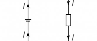
Based on the type of current, electrical networks are traditionally divided into two types - AC and DC networks.
The most common are AC networks. Direct current is most often used to power electrified transport; direct current power supply lines are built for it.
In some individual cases at industrial enterprises there is a need to build direct current power supply systems, for example, for the electrolysis of solutions or electrometallurgy, as well as in the presence of direct current electric drives.
Recently, high-voltage direct current (HVDC) power lines, which are actively used to transmit electricity from alternative energy power plants, have attracted increasing interest from designers.
The advantage of such systems is their greater efficiency, the possibility of parallel operation with different direct current lines (for example, alternating current power lines with frequencies of 50 Hz and 60 Hz cannot be run in parallel), as well as the absence of the need to synchronize power line frequencies.
Classification of electrical networks by voltage
Based on voltage, electrical networks are classically divided into two types - up to 1000 V and above 1000 V. To avoid confusion and ease of operation of serial electrical products in AC installations, the following voltage standards have been adopted:
- Up to 1000 V – 127 V, 220 V, 380 V, 660 V;
- Above 1000 V – 3 kV, 6 kV, 10 kV, 20 kV, 35 kV, 110 kV, 150 kV, 220 kV, 330 kV, 500 kV, 750 kV;
Under normal operating conditions, electrical receivers, depending on their purpose, allow strictly limited voltage deviations from its nominal value. To maintain voltages at a given level, it is necessary to compensate for its loss in transformers. It is for this purpose that the rated voltages of generators, as well as the secondary windings of transformers, have ratings that are 5% higher than those of electrical receivers.
For local lighting networks, low voltages can be used, namely 12 V, 24 V, 36 V.
Classification of electrical networks by purpose
According to their purpose, electrical networks are divided into distribution and supply.
A supply line is a line that supplies power to a substation (S) or distribution point (DP) from a power center (CP) without distributing electrical energy along its length.
Distribution line - a line that supplies power to a number of transformer substations from the distribution center or central processing unit.
In networks with voltages up to 1000 V, supply lines are lines that go from transformer substations to distribution boards or points, and distribution lines are called lines that go directly from distribution boards or points to power receivers.
Below is a high voltage distribution diagram with the presence of a supply and distribution network (a)) and only a distribution network (b)):
High voltage networks are constructed in cases where the voltage source is located quite a long distance away or there are a large number of transformer substations that are significantly distant from each other, for example, when supplying electricity to large industrial enterprises or cities.
Classification of electrical networks according to the principle of construction
According to the principle of construction, electrical networks are divided into closed and open.
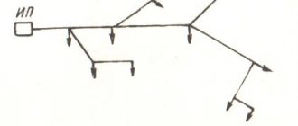
An open network is a set of open lines receiving power from one common power source IP on one side (figure below):
Its main disadvantage is the interruption of power to all electrical receivers in the area where the outage occurred due to a line break.
In a closed system, the opposite is true - power comes from two power supply sources and if the main line breaks anywhere, the power supply to the electrical receivers will not stop. The simplest diagram of a closed network is shown below:
For example, in the event of a line break at point K, power receivers 1,2,3,4 will receive power from the upper line, and 5,6,7,8 from the bottom. Depending on the requirements for reliability of power supply, closed systems may have one or more power sources. Below is an example of a circuit with two-way power supply:
Classification of electrical networks by location
There are external and internal networks.
External networks can be made with bare wires suspended on supports (overhead lines), as well as with special cables laid in blocks (underground lines), trenches, and collectors.
Internal networks are laid inside buildings using insulated wires (insulated wires), cables, busbars (conductors).
Source: https://elenergi.ru/klassifikaciya-elektricheskix-setej.html
Voltage class
Voltage class is a conventional term that allows you to divide equipment into groups according to design and operational characteristics.
From the history of the issue
The history of the development of transmission lines is briefly discussed in the review of two-pole circuit breakers, but let’s try to “take a look around Europe” so that readers can understand the reasons for the need to divide equipment into voltage classes.
Gramma was the first in history to transmit direct current from a dynamo. The inventor of the said equipment sent a current three-quarters of a mile away. This happened at the Vienna Exhibition in 1873.
Previously, there was already a telegraph (with lines up to 20 km), but it was powered by galvanic elements or from a static generator, which has little to do with the topic.
Then there was no need to transmit current over long distances. Used from local generators. For example, to power lighthouses in England and France. All of them rectified the current, as if on purpose, copying modern high-voltage HVDC lines.
A new significant event occurred in 1882, when Oscar von Miller hired the Frenchman Marcel Despres to transmit a voltage of 2 kV over a distance of about 60 km.
This has already become a clear achievement, but a quarter of the original potential difference reached the addressee.
Then a conflict occurred between Edison and Tesla, which ended at the end of the 80s with the creation of new equipment designed for alternating current. Dolivo-Dobrovolsky kept his nose to the wind, and immediately developed a three-phase engine power system. The Russian was not given a patent due to counterarguments from Nikola Tesla, but the battle of currents led to the observation: “The use of a transformer can significantly reduce line losses.”