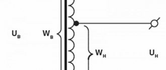
Upon conclusion:
- agreements with an energy sales organization (ESO) for the sale of electrical energy and capacity according to the “energy supply” type
- agreement with the territorial grid organization (TGO) for the provision of services for the transmission of electrical energy
it is necessary to determine the tariff level (range, class) of voltage (CAR) at which the electricity consumer is connected to TSO networks, since according to the tariff voltage level, the value of the tariff for the transmission of electricity or the value of the maximum levels of unregulated prices for electricity, including the tariff for transmission of electricity.
In my opinion, when identifying the tariff level (range) of voltage that determines the size of the tariff for transmission services, the following circumstances must be taken into account:
- The concepts of “voltage level” and “voltage” are different concepts
- The concepts “actual voltage level” and “actual voltage” are different concepts
- When determining the actual voltage level, it is necessary to take into account where the balance line (hereinafter referred to as GBP) is located: at the “power source” or not?
- An algorithm for determining the value of the electricity transmission tariff used for calculations when directly connecting the consumer’s power receiving devices (hereinafter referred to as EPU) to TSO power grid facilities
From the history of the issue
The history of the development of transmission lines is briefly discussed in the review of two-pole circuit breakers, but let’s try to “take a look around Europe” so that readers can understand the reasons for the need to divide equipment into voltage classes. Gramma was the first in history to transmit direct current from a dynamo. The inventor of the said equipment sent a current three-quarters of a mile away. This happened at the Vienna Exhibition in 1873. Previously, there was already a telegraph (with lines up to 20 km), but it was powered by galvanic elements or from a static generator, which has little to do with the topic.
Then there was no need to transmit current over long distances. Used from local generators. For example, to power lighthouses in England and France. All of them rectified the current, as if on purpose, copying modern high-voltage HVDC lines. A new significant event occurred in 1882, when Oscar von Miller hired the Frenchman Marcel Despres to transmit a voltage of 2 kV over a distance of about 60 km. This has already become a clear achievement, but a quarter of the original potential difference reached the addressee.
Then a conflict occurred between Edison and Tesla, which ended at the end of the 80s with the creation of new equipment designed for alternating current. Dolivo-Dobrovolsky kept his nose to the wind, and immediately developed a three-phase engine power system. The Russian was not given a patent due to counterarguments from Nikola Tesla, but the battle of currents led to the observation: “The use of a transformer can significantly reduce line losses.”
Which turned out to be immediately used. In 1891, a voltage of 15 kV was transmitted over as much as 180 km with an efficiency of 75%. Edison is resting! From this time on, the advantages of alternating current became obvious; low voltage caused high losses in the line. This is the main reason why in the modern world there is a need to divide equipment into voltage classes.
Already in 1912, the voltage reached 110 kV, ten years later it was 220. The rate of voltage growth showed an exponential dependence on the passing years. Then lines for 380, 765 (750) and 1200 kV were constructed.
Classification of electrical networks according to the principle of construction
According to the principle of construction, electrical networks are divided into closed and open.
An open network is a set of open lines receiving power from one common power source IP on one side (figure below):
Its main disadvantage is the interruption of power to all electrical receivers in the area where the outage occurred due to a line break.
In a closed system, the opposite is true - power comes from two power supply sources and if the main line breaks anywhere, the power supply to the electrical receivers will not stop. The simplest diagram of a closed network is shown below:
For example, in the event of a line break at point K, power receivers 1,2,3,4 will receive power from the upper line, and 5,6,7,8 from the bottom. Depending on the requirements for reliability of power supply, closed systems may have one or more power sources. Below is an example of a circuit with two-way power supply:
Meanwhile in Russia
Russia was lagging behind in development. Either the secret party cells of the first revolutionaries took away the strength of the state, or an evil fate prevented the country from keeping up with the times, the fact remains that it was not possible to catch up and overtake the West, the only high-voltage line was broken by the exclusion of Kazakhstan from the Russian Federation during the coup of the 90s .
Global energy consumption doubled every ten years during the first oil crisis. By the beginning of the 80s, the first ultra-high voltage lines were built:
- 1150 kV AC.
- 1500 kV DC.
In 1980, there were 70 power plants operating in the USSR, providing the country with 1 GW or more of power. Between 1960 and 1990, the length of Soviet state lines increased from 0.22 to 5.1 million km. At the time of the end of “perestroika,” the emphasis was on networks with a voltage class of 220 kV. Over the past years, the length of lines from 330 to 750 kV has almost doubled. Soviet politicians considered the Siberia-Ekibastuz-Ural line to be the apogee of development, where the highest potentials indicated in the text were applied.
A kilometer of line already in those days cost 10–100 thousand rubles. The numbers can increase many times over when laid under special conditions. This also applies to ultra-high voltages. Raising the voltage at high costs is acceptable; the costs of constructing power lines, converters and equipment are offset by savings on leakages. DC lines almost do not form corona discharges, so the voltage was raised to 1.5 MV, significantly reducing power losses due to the ohmic resistance of copper conductors.
Air line
In the development of any class of electrical equipment, the need to increase the transmitted power invariably arises. The most effective way is to increase the network voltage. As the current increases, energy losses by heat through the ohmic resistance of the wires increase sharply. As a result, different insulation requirements arise. If in a household circuit it is tested with current clamps with a 500 V attachment, in equipment of 6.6 or 110 kV it does not look serious.
For example, oil transformers obviously withstand higher voltages than conventional ones, because the conditions for the occurrence of an arc are deliberately created unfavorable. Consequently, in transformers, the key feature of the transition to a new class is the introduction of oil insulation. The same is said about cables, but in push-button posts the measure means something else - a transition to the category of equipment used in explosive areas.
New challenges force engineers and inventors to look for fresh technical solutions. And in each case there is a special task. It is impossible to compile a single list of voltage classes for the entire list of equipment available in industry. Obviously, there is no point in dividing household appliances by voltage classes, but the gradation remains. For example, AC power systems with voltages below 50 V and DC power systems of 120 V are considered safe and can be used in bathrooms, toilets, and kitchens.
Voltage classes
Voltage classes are quite noticeable in technology. You can find documents with similar content on the Internet:
- STO 56947007-29.130.20.104 Standard technical requirements for switchgear (complete distributed devices) of voltage classes 6-35 kV.
- GOST R 51559 Power oil transformers of voltage classes 110 and 220 kV and autotransformers with voltage of 27.5 kV for AC electric railways.
- GOST 12965 General purpose power oil transformers of voltage classes 110 and 150 kV.
- STO 56947007-29.130.10.077 Standard technical requirements for disconnectors of voltage classes 6-750 kV.
- GOST 1516.1 AC electrical equipment for voltages from 3 to 500 kV. Requirements for electrical insulation strength.
From the given names, you can see that voltage classes are rarely listed, because this concerns professionals, and they are aware of what requirements this or that equipment must satisfy. Often the grading of some authors contradicts other sources. Probably the division was made according to different factors. Let’s say that in one case design features were taken into account, in another – operational features. An outdated classification of power lines may look like this:
- Up to 1 kV – low voltage.
- Over 1 kV – high voltage.
- 330-500 and 750 kV – ultra-high voltage.
- Over 1 MV – ultra-high voltage.
Here's some other information:
- 380 V or less – low voltage.
- From 1 to 20 kV – average second voltage.
- 35 kV – average first voltage.
- 110 and 220 kV – high voltage.
- 330-500 and 750 – ultra-high voltage.
- Above 1 MV – ultra-high voltage.
It can be seen that some of the names do not match, so the voltage classes are indicated in numbers to avoid confusion. The designation usually includes phase voltage.
Line design
From the above we can conclude that the design of power transmission lines is individual for each voltage class. For example, high-voltage ceramic insulators can break a local 220V distribution pole in windy weather if hung on each line.
Low-voltage lines (see classification above) are built on single poles directly buried in the ground. Here the step voltage does not seem to be too high in the event of an accident, the only protective measure will be a local grounded lightning rod. Lines up to 20 kV differ little in design from those described. But the dimensions of the pillars, the distance between the cables, and the insulators have been increased. Lightning protection cables are not used; this is not economically justified.
Starting from 35 kV lines, the design becomes more complex; steel lightning protection cables are suspended in areas with intense thunderstorm activity. A heavy cable is used, the breaking strength of the pole is increased. The increased distance between the wires is ensured by powerful insulators mounted on special crossarms. Some poles are already reminiscent of high voltage. They consist of individual prefabricated steel sections mounted on insulating concrete slabs to block the flow of current to the ground in the event of an accident. Above 35 V, steel-aluminum cables are often used, where the load-bearing functions are assigned to a high-strength core.
On power lines with a voltage class of 110 kV, lightning protection cables are suspended along their entire length, on 35 kV lines - only in the area of substations. 330 kV lines resemble 35 in shape, but the arched poles are taller and more powerful, and much more insulators are hung to block the occurrence of an electric arc and reduce the formation of corona discharges. Lightning protection in the form of wires may not be available in windy regions where an overlap with a line causes a short circuit. The effect is also used for protection during operation of a zero-sequence relay.
Grounding conductors for high-voltage lines are usually located inside concrete supports to reduce the step voltage. In this case, the currents immediately flow underground and do not cause such destructive damage to random passers-by and animals. Starting from 500 kV, lightning protection cables are conductive and are used for communication in the form of a steel rope with one twist of aluminum wires. At these voltages, split wire is used, which sharply reduces corona losses and reduces the electromagnetic field strength. At the same time, the reactance of the line is reduced, which makes it possible to use reactors of smaller capacity and size at substations.
When a 500 kV line is split in two, the throughput increases by 21%, and in three – by 33%. This event complicates the design of insulating suspensions and reinforcement of supports. An increase in the cost of a line is not always compensated by the economic benefits received. In the Russian Federation, lines are split according to voltage classes:
- 330 kV - in two.
- 500 kV – three times.
- 750 kV – for 4 or 5 lines.
- 1150 kV – 8 lines.
The wire is divided into classes:
- Pure aluminum or steel – up to 20 kV.
- Steel-aluminum wires of the 4th group - from 35 to 110 kV.
- Steel-aluminum wires of the 3rd group - 220 kV and above.
The concepts “actual voltage level” and “actual voltage” are different concepts
To determine the tariff for electricity transmission, it is important to establish at what “actual voltage level” the electricity consumer is connected. Not at what “ actual voltage ”, but at what “ actual voltage LEVEL ”. It's not the same thing.
These concepts become almost identical in a situation where the consumer’s balance sheet boundary is NOT at the POWER SOURCE.
In this case, the “ actual voltage ” of the consumer’s EPU at the point of connection to the TSO power grid facilities is taken as the “ related to the corresponding “ voltage level
That is, the “actual voltage” of the EPU coincides with the “voltage” that refers to one or another “voltage level”. “ Actual voltage ” of the consumer’s EPU at the point of connection to the electric grid facilities TSO PREDETERMINES the “actual voltage LEVEL” used to select the tariff for electricity transmission.
For example, if you have the “actual voltage” of the EPU at the point of connection to the TSO power grid facilities is 6 kV, and this connection point is NOT at the power source, then the voltage related to the corresponding “ voltage level ” will also be 6 kV. Therefore, the “voltage level” will be “average second” (CH2), since the EPU voltage completely coincides with the voltage related to the second “voltage level” (CH2). Hence, your “actual voltage level” at which your EPUs are connected to the TSO power grid facilities will be completely determined by the above-mentioned coincidence of “voltages”: the EPU voltage and the voltage related to the corresponding “ voltage level ”.
Next, based on the “actual voltage level”, according to the TSO tariff menu, we determine the value of the tariff for electricity transmission corresponding to the voltage level - the average second voltage (CH2).
The situation is completely different when the consumer’s balance sheet boundary is at the POWER SOURCE.
Differences by voltage classes
Using the example of power lines, the difference in design by voltage class is demonstrated. At the same time, operational features arise - protection measures, repair and construction techniques. Each case has specific requirements. You should not be surprised if the wires are divided into voltage classes in one order, and insulators and lightning protection cables - in another.
It is obvious that climatic conditions impose certain requirements, and physical processes – others. Exactly the same is said about electrical equipment, where the division into voltage classes differs.