Electricity metering with a current consumption of more than 100A is carried out by transformer connection meters, which are connected to the measured load through measuring transformers. Let's consider the main characteristics of current transformers.
1 Rated current transformer voltage.
In our case, the measuring transformer should be 0.66 kV.
The accuracy class of measuring current transformers is determined by the purpose of the electric meter. For commercial accounting, the accuracy class must be 0.5S; for technical accounting, 1.0 is allowed.
This parameter is the most important for designers. Now we will consider the requirements for choosing the rated current of the primary winding of an instrument transformer. The rated current of the primary winding determines the transformation ratio.
The transformation ratio of an instrument transformer is the ratio of the rated current of the primary winding to the rated current of the secondary winding.
The transformation ratio should be selected according to the design load, taking into account operation in emergency mode. According to the PUE, the use of current transformers with an increased transformation ratio is allowed:
1.5.17. It is allowed to use current transformers with an increased transformation ratio (according to the conditions of electrodynamic and thermal resistance or busbar protection), if at the maximum load of the connection the current in the secondary winding of the current transformer is at least 40% of the rated current of the meter, and at a minimum operating load - at least 5 %.
In the literature you can also find requirements for the selection of current transformers. So, a current transformer should be considered overestimated in terms of transformation ratio if, at 25% of the calculated connected load (in normal mode), the current in the secondary winding will be less than 10% of the rated current of the meter.
Now let’s remember the mathematics and look at these requirements using an example.
Let the electrical installation consume a current of 140A (minimum load 14A). Let's choose a measuring current transformer for the meter.
Let's check the measuring transformer T-066 200/5. Its transformation coefficient is 40.
What kind of lighting do you prefer?
Built-in Chandelier
140/40=3.5A – secondary winding current at rated current.
5*40/100=2A – minimum current of the secondary winding at rated load.
14/40=0.35A – secondary winding current at minimum current.
5*5/100=0.25A – minimum secondary winding current at minimum load.
35/40=0.875 – current in the secondary load at 25% load.
5*10/100=0.5A – minimum secondary winding current at 25% load.
Conclusion: the T-066 200/5 measuring transformer for a 140A load is selected correctly.
For current transformers, there is also GOST 7746-2001 (Current Transformers. General Technical Conditions), where you can find the classification, main parameters and technical requirements.
Expert opinion
It-Technology, Electrical power and electronics specialist
Ask questions to the “Specialist for modernization of energy generation systems”
Selection of current transformers for a 0.4 kV electric meter | Power supply design Despite its widespread use, such equipment belongs to devices of a low accuracy class and is characterized by increased energy consumption, and the errors in the data obtained are especially noticeable in conditions of low load on the network. Ask, I'm in touch!
Electronic or induction
Experts in the field of electrical engineering note that today consumers prefer electronic types of reading devices, since their accuracy class is lower than that of induction devices.
The meter's transformation ratio affects the accuracy of the final readings. On average, induction samples have an accuracy class of 2.5, while electronic samples have an accuracy class of 2.0. This means that the reading error as a result of the operation of an electronic-type electrical reading device is up to 2%, and for an induction one - 2.5%. It is for this reason that electronic equipment is now more often installed, since it allows you to save more by getting more accurate readings. Experts strongly do not recommend installing equipment with an overestimated transformation ratio. In modern electrical engineering, it is customary to use transformers with a static CT, which is guaranteed not to change during operation.
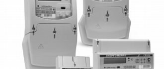
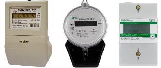
Such electric meters include Mercury-230. Mercury-230 is produced in Russia and is considered one of the best samples for commercial and private use. Mercury-230 can be manufactured for single- and double-tariff plans. Typically, the Mercury-230 model supports a three-phase electrical network. On average, the warranty period for Mercury-230 is 25 years, which is the optimal choice when taking into account quality and price. Mercury-230 fully complies with GOST standards.
Mercury-230 has a good accuracy class and operates stably under significant changes in ambient temperature throughout the entire life of the device. Mercury-230 allows you to accurately measure the current parameters of the electrical network - frequency, power factor, current value of phase current, voltage.
Tariffizer Mercury-230 allows you to simultaneously take into account readings at 4 tariffs in 16 time zones of the day, as well as for four types of days. Mercury-230 can take into account forward active electricity and its total power by phase, the sum of the phase values with determining the direction of the total power vector.
Types of electricity metering devices
All meters existing today are divided according to the principle of their operation; there are three-phase and single-phase. They are not connected to the network directly; in most cases, there is a transformer between them in the circuit. But direct connection is also possible. For networks with voltages up to 380V, electricity meters from 5 to 20A are used. We already know that the transformation ratio is the difference between the voltage at the input to the transformer and the voltage at its output.
The electricity meter receives clean electricity that has a constant value. Today they resort to the use of two main types of metering devices. Until the mid-nineties of the last century, mainly induction type meters were installed. They continue to work today, but they are gradually being replaced with electronic meters (this statement also applies to the general house meter).
The induction type meter has an outdated design. Its operation is based on the interaction of magnetic fields produced in inductive coils and a disk, which reads the electricity consumption during rotation. The disadvantage of these devices is that they are not able to provide multi-tariff metering. In addition, there is no possibility of remote data transfer.
The operation of electronic meters is based on microcircuits; they directly convert the read signals. These devices have no rotating parts, which significantly increases their reliability and service life. Simply put, the transformation ratio of the meter has a direct impact on the accuracy of the data it produces.
Previously, the accuracy rating was 2.5, but the metering devices used today have an accuracy rating of 2.0. Electronic equipment has such high accuracy data. Today, only electronic meters are installed everywhere, which are confidently replacing induction ones.
Today, the cost of obtaining energy supply services is constantly growing, which provokes the need to implement a system of monitoring and accounting for the resource consumed. A very important value that must be taken into account is the special transformation ratio of the meter. In this article we will tell you about the types of modern reading devices that connect to the network, their advantages and disadvantages, as well as how to independently determine the transformation ratio.
Every owner, before purchasing equipment to control energy consumption, must understand that the operation of such a device will depend on the principle of operation. It is the operating principle of electricity meters that divides them into two main types: electronic and induction. Electronic electrical meters are always based on the fact that they take a direct measurement of the current and voltage on the power line passing through the system. The scale of this type of equipment is an electronic type of dial, and also has the unique ability to store the values of consumed electricity in the built-in memory.
In this type of electricity meter there are no mechanics, and the current itself will pass through microcircuits and semiconductors directly. The advantages of this type of equipment include its small size and weight, ease of connection, due to the variety of models produced. Electronic electricity meters can be manufactured specifically for one- or two-tariff accounting. They can be installed in a special automated system for commercial accounting of consumed electricity.
Despite the fact that these devices have a wider range of functionality than other types, its interface is quite simple and understandable. Thanks to the digital values on the scale, owners are able to accurately read the necessary information from the electronic meter. This type of reading equipment has a shorter warranty period because it is not as reliable as the induction type.
Induction electric meters are currently the most common. They are a mechanical structure in which two special coils are installed - for current and voltage. When this counter works, a magnetic field is formed, which sets these coils in motion. The discs, in turn, begin to move the scale with the values on the dial, which as a result displays the amount of electricity consumed.
The speed of the system will directly depend on the voltage level in the electrical network. The greater the power value, the higher the disk rotation speed. When counting, the induction type of energy supply meters has errors when counting. In order to increase the accuracy class of readings, an expensive expenditure will be required. The average service life for such equipment is usually about 15 years.
During the purchase, you can read the technical data sheet of a specific model of electric meter to find out about all the characteristics and parameters of the equipment that it has. This will allow you to choose the optimal sample for your home. The transformation coefficient of an electrical reading device does not directly relate to the design itself, but is an intermediate indicator that mainly depends on the transformer.
Types and rules for choosing an electric current converter
Transformer equipment that reduces current (CT) is classified according to various characteristics, including conversion ratio. This equipment is required if the facility consumes power that is several times greater than the capabilities of a conventional node.
The CT converts the current to a level that allows you to connect conventional one- or three-phase electricity meters for monitoring and create a line protection system.
Classification
By installation method
According to this principle, CTs are divided into:
- supporting (installed on the surface);
- pass-through (attached to the busbar);
- tire (attached to the tire);
- built into power electric current systems;
- detachable (installed on cables).
By type of insulation
An electric current transformer can be:
- with epoxy resin or special varnish;
- in a plastic case;
- with solid insulation made of porcelain, bakelite. hard plastic;
- with a viscous composition (oil);
- filled with gas;
- with oil-paper insulation.
What parameters to consider
To calculate the readings of an electric meter with current transformers, the transformation ratio is important. It can be single-stage or cascade (multi-stage). The last type of CT is distinguished by the presence of several secondary windings and a large number of turns in the primary winding.
It is not advisable to buy a TT with too high a transformation level. With such a choice, you will have to install a counter at the receiving input. More popular are converters with one coefficient, which do not change the reading during operation. When using them, the problem of how the readings of an electricity meter connected through current transformers are calculated is easier to solve.
Calculation of electricity using a meter with current transformers can only be carried out if the transformation ratio is known. It must be indicated in the technical documentation with which the TT was sold and on the body. If you suspect inaccuracies in the displayed figures, you can calculate the coefficient yourself.
To calculate the ratio, you need to connect the converter to the electric current that creates a short circuit in the secondary winding and measure how many amperes there are in it.
Transformation ratio is the ratio of the values of the supplied electric current and the current passing in the secondary winding.
For example, if a short circuit is caused by 150 A, on the secondary winding 5 A, the effective coefficient is 30. This is a more accurate value than the nominal value, which is determined by the rated electric current of the primary and secondary windings. The result of calculating electric meter readings with current transformers is more accurate.
Calculation of indirect connection meter readings
CTs are installed in networks that consume hundreds of kilowatts of electrical energy. The operating principle of such a converter is based on reducing the electric current to a value that allows connecting a standard electric meter through it. For example, a 5 A meter, in a 150 A network, the CT should reduce the indicator by 30 times, that is, the transformation coefficient used in calculating the flow rate is also 30.
How to read a meter with a current transformer? You just need to count them and subtract the indicator read at the beginning of the billing period.
Then the resulting figure is multiplied by the transformation coefficient specified in the technical documentation or the electricity supplier’s report, calculated independently. This is the answer to the question of how to calculate electricity with current transformers.
How to determine the transformation ratio: formula
The transformation ratio of an electricity meter indicates how many times the input parameters of voltage or current differ to a lesser or greater extent from the output parameters.
For indicators exceeding one, a decrease is made, and, conversely, for indicators less than one, a device of an increasing type is used.
Transformation ratios for voltage or current differ.
Calculation formula: k=U1/U2=N1/N2 ≈ I2/I1, where:
- U1 and U2 – difference in electrical voltage on the primary and secondary windings;
- N1 and N2 – number of turns of the primary and secondary windings;
- I2 and I1 – indicators of current strength in the primary and secondary windings;
- k – required CT parameters.
As a rule, such parameters of the transformation ratio are necessarily indicated in the accompanying documentation that comes with the equipment. You can also find out this information from the markings on the body of such a device.
A difficult situation is when the CT needs to be calculated independently, according to data obtained empirically. In this case, current is passed through the primary winding of the equipment and a short circuit is made on the secondary winding, after which the amount of electric current passing through the secondary winding is measured.
Independent calculation involves dividing the value of the primary current by the value of the secondary winding. The result of such calculations is a quotient represented by the transformation coefficient.
Connection diagrams
Electrical meters and transformers are connected taking into account safety requirements and operating rules, as well as the characteristics of the device itself. The minimum installation temperature is +5˚ Celsius. Otherwise, a correct technical connection will not work - devices that operate with voltage and current do not tolerate low temperatures well.
If you need to connect a transformer outdoors during the cold season, you need to build a special cabinet - insulated and sealed. The device itself is usually installed at a height of 1-1.7 meters.
Installation of a meter with current transformers
It is not always possible to measure consumed electricity through a meter connected directly to the power supply (to an outlet). In circuits with a voltage of 380 Volts and current limits greater than 100A - accordingly, consumption increases to 60 kW - installation of a measuring current transformer is required. Masters call such a connection indirect, but this method provides the most accurate data. In addition, there are two more methods:
The first is used in industrial enterprises and large factories with a power consumption above 0.4 kW and a current of more than 100A.
The “star” scheme, in turn, can be complete or incomplete. For a full star, devices with uniform load distribution and symmetrical current flow are suitable. The transformer is installed on all phases, and the relay winding is connected in a star shape.
Incomplete - two-phase two-relay circuit with the formation of a star part. This circuit quickly responds to short circuits (except for grounding), and it is also possible to install it on interphase panels.
Installation of a multi-turn meter
A three-phase transformer connection meter is used in multi-wire networks. For multi-turn connections, the primary winding of the coil is replaced with a cable one. The device controls the movement of current through the secondary winding. Otherwise, the transformer works on the same principle as other types of equipment.
Ten-wire circuit
This connection method is suitable for use in powerful power circuits, the operation of which is provided by transformers. Galvanic type isolation is suitable for industrial and domestic needs and guarantees the safe operation of the equipment. Connection sequence by terminals (from first to last):
- phase, input (A);
- phase mechanism measuring circuit, input;
- measuring drive, output (A);
- terminal, phase, input;
- phase mechanism measuring circuit, output (B);
- phase, output (B);
- phase, input (C);
- circuit, phase measurement - input.
Seven-wire circuit
This connection scheme has a number of advantages and some disadvantages. Slightly different from ten-wire. It is convenient to work with the meter - there is no need to completely turn off the system when working with the panel, metering devices and transformers.
Thanks to grounded current circuits, dangerous potential does not accumulate at the outputs of the secondary windings, which often leads to short circuits and equipment burnout. A test box is connected to the general network, which allows you to safely disconnect the power circuits.
The seven-wire method is one of the outdated ones and is rarely used. Electrical installers from professional companies do not recommend connecting using more modern methods.
Scheme with combined circuits
This scheme differs significantly from the previous ones. Current transformers with combined circuits are connected through special jumpers (the path is from L1 to L2).
Other connection systems
In addition to those indicated, there are other schemes for connecting the meter to the transformer. The use of a test block in a connection - in accordance with clause 1.5.23 of the Electrical Installation Rules - is necessary when activating a model meter. This is additional equipment that allows you to bypass and disconnect current circuits, activate meters without reducing the voltage load. Another point is the possibility of taking readings in phases.
The basis of the connection through the test box is a ten-wire circuit. The difference lies in the installation between the metering device and the transformer structure of the transition block with the necessary protective and distribution functions.
Accounting Features
To reduce energy losses, electricity is transported through high-voltage lines; voltage-reducing transformers are used to bring the network characteristics into line with the parameters of household appliances.
Thus, the home electric meter does not record real consumption, but only the amount of electricity with reduced voltage, therefore, to determine the exact costs, it is necessary to multiply the readings of the meter by the transformation ratio. Correspondence between transformation ratio and rated voltage Many utility companies do this in advance when compiling tariffs for the population, in which case the average value is used.
Technical characteristics of the coefficient
Transformation ratio is the ratio of load currents and electric meter. In this case, it will always be greater than unity, since the consumption currents exceed the measuring currents. When calculating the consumed electricity, the readings on the dial or panel are multiplied by this coefficient. The resulting value is the correct number of kilowatt-hours consumed.
Transformers also have an accuracy class. For electricity metering equipment it is equal to 0.2 or 0.5. The lower the class value, the higher the accuracy of the measuring instruments.
Tips and tricks
However, when using a large number of household appliances with different power ratings, it is recommended to give preference to three-phase meters, which allows you to connect energy-intensive devices that are designed for voltages of 220 V and 380 V.
When choosing a device, you must pay attention to the calculated current indicators, as well as the accuracy class, represented by the largest permissible relative error, expressed as a percentage. All newly installed three-phase meters must have state verification seals that are not older than twelve months
The age of the seal on a single-phase meter cannot exceed two years
All newly installed three-phase meters must have state verification seals that are not older than twelve months. The seal on a single-phase meter must not be older than two years.
How to take meter readings correctly?
Counters come in two designs:
- Induction devices are “old-fashioned” bulky devices with a rotating wheel.
- Static - or modern electric.
Many people still have induction ones, but the trend towards switching to electronic models is already clearly visible - they calculate more accurately, look better, and do not make noise.
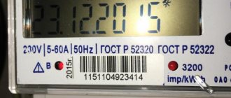
When taking readings from an induction device, pay attention to the first 5 digits (some models have 4). The last digit is usually placed slightly separately or highlighted in a different color, it rotates relatively quickly - it is, as a rule, not written on the receipt (for an even and simpler counting) - this is the reading after the “decimal point”
The last digit is usually placed slightly separately or highlighted in a different color, it rotates relatively quickly - it is usually not written on the receipt (for an even and simpler counting) - this is the reading after the “decimal point” in the decimal fraction.
It is better to take data on the same day of the month. In some regions of the country, it is customary to call the MES or RES on your own (on the appointed day) and report your readings.
Otherwise, the organization makes calculations based on average consumption over the past months - this data will be reflected in the receipt.
How to take readings from an electronic meter, multi-tariff readings
The electronic device can calculate a single tariff, or can be configured to count for several tariffs (different tariffs are introduced for the purpose of saving - during the day they are a little more expensive than usual, and at night they are much cheaper).
The desired mode is selected in the device menu (modes are usually changed by repeatedly pressing the enter button):
- T1 – for single tariff.
- T2 – for separate payment of the grace period from 23:00 to 7:00 am.
- T3 – one standard tariff and two preferential ones.
When these modes (T1 and T2) are displayed alternately, the device will show different readings that have accumulated over the month at a given tariff.
The difference with previous readings is calculated for each tariff separately.
How to take readings from an electric meter when replacing it
Meters are replaced due to their obsolescence, when inaccurate readings are suspected, and for periodic testing in the laboratory. What to do with the readings if the old meter was dismantled and a new one was installed?
Before the old meter is removed, the readings from it are copied onto paper.
You will need to pay off the outstanding balance on the meter.
All other manipulations will be done by the controller.
He will seal the new meter, draw up documents for it and transfer them to the service organization.
Next time the receipt will come with a new number and readings of the installed meter.
By the way, many people are interested in whether it is possible to replace the electric meter yourself? Yes, it is possible, but you must first notify the RES (you can do it by phone).
But the company controller must seal the meter.
How to choose current transformers for connecting metering meters
Meters for payments for consumed electricity between the energy supplying organization and consumers should be installed at the boundary of the network section according to the balance sheet and operational responsibility between the energy supplying organization and the consumer. The number of meters at the facility should be minimal and justified by the adopted power supply scheme of the facility and the current electricity tariffs for a given consumer. Settlement meters for tenants located in residential, public and other buildings and isolated in administrative and economic terms must be installed separately for each independent consumer (organization, house management, studio, store, workshop, warehouse, etc.).
The transformation ratio of current transformers should be selected based on the calculated connected load, taking into account the operation of the installation in emergency mode. A current transformer is considered to be overestimated in terms of its transformation ratio if, at 25% of the calculated connected load (in normal mode), the current in the secondary winding will be less than 10% of the rated current of the meter (rated current of the meter is 5 A).
Depending on the resistance values of the consumers of the secondary circuit Z 2, Ohm, and the secondary load of the current transformer S2, VA, the same current transformer can operate in different accuracy classes. To ensure sufficient accuracy of instrument readings and the operation of protection devices connected to the current transformer, it is necessary that the value of Z2 does not exceed the rated load of the current transformer.
Current transformers have current ΔI and angular errors δ. Current error, percent. according to the given ratio is taken into account in the readings of all instruments:
where knom is the nominal transformation ratio; I1 and I2 are the current of the primary and secondary windings of the transformer, respectively.
The angular error is determined by the angle δ between the current vectors I1 and I2 and is taken into account only in the readings of meters and wattmeters.
Current transformers have the following accuracy classes: 0.2; 0.5; 1; 3; 10, which corresponds to the current error values, percent. The accuracy class of current transformers for commercial metering meters should be 0.5; for electrical measuring instruments - 1; for current protection relays - 3; for laboratory instruments - 0.2.
An example of selecting current transformers for connecting a meter.
The estimated connection current in normal mode is 90 A, in emergency mode - 126 A.
Current transformers with a transformation ratio n t = 150/5 are selected based on the load in emergency mode.
Examination. At 25% load, the current in the primary circuit is I1 = (90 x 25)/100 = 22.5 A.
The current in the secondary circuit (with a transformation ratio n t = 150. 5 = 30) will be
I 2 = I1/nt = 22. 5/30 = 0.75 A.
The current transformers are selected correctly, since I 2 > I n of the meter, i.e. 0.75 > 0.5.
The cross-section of wires or cables from current transformers to meters must be no less than: copper - 2.5, aluminum - 4 mm2. The maximum cross-section of wires and cables that can be connected to the meter terminals should not exceed 10 mm2.
When selecting current transformers for metering meters, it is recommended to use data from the PUE (table “Selection of current transformers”). To metering devices mounted at the input for the purpose of safe installation, testing and replacement of meters and current transformers in electrical installations in the presence of two supply lines (inputs) and two distribution assemblies having switching devices for connecting them (sectional switches, automatic transfer switches, etc.), disconnecting devices must be installed before the metering devices mounted at the input, and after the metering devices - devices that ensure circuit breakage on the side of the distribution assemblies.
How electricity meter readings are transmitted
Many apartment owners are wondering until what date to submit electricity meter readings and how exactly this procedure should be carried out. Due to the innovation that came into force 4 years ago, the rules for transmitting testimony have changed. According to it, individuals must independently transfer factual data to local electricity sales authorities.
Previously, this responsibility was assigned to the employees of the organization itself. Every month they visited apartments to take readings and check electricity meters at home. After this, each apartment owner received payment notifications on the first days of the month.
In 2012, a new decision came into force. According to it, electricity sales employees are required to check meter readings not once a month, but quarterly. During the remaining period, apartment owners must independently monitor the readings of their devices and transmit data.
In order to optimize this process, energy sales organizations have come up with a whole system for transmitting electricity meters in order to eliminate the inconvenience associated with changes and get rid of queues. Thanks to this, data can be transferred even via the Internet or one phone call.
There are several ways to solve the problem of removing electricity credentials.
Some consumers are trying to save money on utility bills by “cheating” the magnetic seal on the electric meter. Most often, neodymium magnets are used for this. With their help, the electromechanical counter stops.
For this reason, regulatory authorities install anti-magnetic seals on consumer electricity meters. Outwardly, they resemble a sticker, but its structure is much more complex than it might seem at first glance. Inside the seal there is a sensor that records magnetic changes. When a certain threshold is crossed, the device is triggered. As a result, when the time comes to verify the electricity meter, an employee of the regulatory authorities will be able to determine the presence of outside interference by the appearance of the device.
The sensor itself is a small capsule filled with a substance that reacts sensitively to the presence of a magnetic field. If such an intervention has taken place, the contents spread throughout the capsule. After this, no means can restore it to its original appearance. A completely colored capsule will indicate that an attempt was made to stop the metering device.
Sealing is carried out when it is time to replace the electric meter or there is a need for its repair. All costs for servicing the device are covered by the owner, but installation of the seal is performed free of charge. If repairs or replacement of the electric meter are expected, the price is already included in the cost of these procedures. If they resort to sealing again, in this case the service will need to be paid (from 100 to 500 rubles, depending on the region of residence).
Forcing the owner to pay for the initial installation of a seal after the above maintenance is considered illegal. In such cases, there are several ways to solve the problem:
It is worth noting that for household electricity meters the price for installing a seal is low, so the apartment owner independently decides whether to pay for this service or not.
If the seal installed on the electric meter is broken, you should not wait until they come to check it. The electrical supply company must be notified immediately. In this case, it is necessary to provide a reliable explanation of what happened.
If intentional damage to the seal is discovered, the cost of checking the electric meter without removing it will also include a huge fine. To calculate its amount, certain calculations are carried out. The fine is calculated based on the maximum amount of electricity that was available to the apartment owner during the period until the inspector appeared.
The available amount of electricity is determined based on the rated current readings on the circuit breaker, which is installed at the electricity input to the home.
In addition, the energy supply company records all instrument readings on a monthly basis and compares the results of the devices at the substation. If a difference is detected, an investigation is carried out to identify the thief. Therefore, you should not joke with meters, otherwise the amount of the fine will significantly exceed the money saved by stopping the device.
Schemes for connecting the meter via current transformers
For correct metering of electricity using CTs, it is necessary to observe the polarity of connecting their windings: the beginning and end of the primary are designated L1 and L2, the secondary - I1 and I2.
Schemes for semi-indirect connection of three-phase electric meters (using only CTs) can be made in different versions:
Seven-wire. This is an outdated and least preferred scheme in terms of electrical safety due to the presence of a connection between current and measuring circuits - the current circuits of the electric meter are energized.
Ten-wire circuit. More preferred and recommended for current use. The absence of a galvanic connection between the current circuits of the meter and voltage circuits makes connecting the meter safer.
Connection diagram for an electric meter through a test block. According to the requirements of PUE clause 1.5.23, it should be used when connecting a model meter through a CT. The presence of a test box allows for shunting, disconnecting current circuits, connecting a meter without disconnecting the load, and phase-by-phase voltage removal from the measured circuits.
The connection is made on the basis of a ten-wire circuit; its difference from the latter is the presence of a special test adapter block between the electric meter and the CT.
With CT connection in a “star”. Some terminals of the secondary windings of the CT are connected at one point, forming a “star” connection, others - with the current coils of the meter, also connected according to the “star” circuit.
The disadvantage of this method of connecting metering is the great complexity of switching and checking the correct assembly of the circuit.
How to determine the transformation ratio: formula
For indicators exceeding one, a decrease is made, and, conversely, for indicators less than one, a device of an increasing type is used.
Transformation ratios for voltage or current differ.
- U1 and U2 – difference in electrical voltage on the primary and secondary windings;
- N1 and N2 – number of turns of the primary and secondary windings;
- I2 and I1 – indicators of current strength in the primary and secondary windings;
- k – required CT parameters.
As a rule, such parameters of the transformation ratio are necessarily indicated in the accompanying documentation that comes with the equipment. You can also find out this information from the markings on the body of such a device.
A difficult situation is when the CT needs to be calculated independently, according to data obtained empirically. In this case, current is passed through the primary winding of the equipment and a short circuit is made on the secondary winding, after which the amount of electric current passing through the secondary winding is measured.
Main parameter of the transformer
The main characteristic of any transformer is the transformation ratio. It is defined as the ratio of the number of turns in the primary winding to the number of turns in the secondary winding. In addition, this value can be calculated by dividing the corresponding EMF indicators in the windings.
Formula
In the presence of ideal conditions, when there are no electrical losses, the solution to the question of how to determine the coefficient is carried out using the ratio of the voltages at the terminals of each winding. If the transformer has more than two windings, this value is calculated for each winding in turn.
In step-down transformers, the transformation ratio will be above unity; in step-up devices, this indicator ranges from 0 to 1. In fact, this indicator determines how many times the voltage transformer reduces the supplied voltage. It can be used to determine the correct number of turns. This coefficient is determined on all available phases and on each branch of the network. The data obtained is used for calculations, making it possible to identify wire breaks in the windings and determine the polarity of each of them.
You can determine the real transformation ratio of the transformer current using two voltmeters. In transformers with three windings, measurements are made on at least two pairs of windings with the lowest short-circuit current. If some elements of the transformer and branches are covered with a casing, then determining the coefficient becomes possible only for the terminals of the windings brought out.
In single-phase transformers, to calculate the operating transformation ratio, a special formula is used in which the voltage supplied to the primary circuit is divided by the simultaneously measured voltage in the secondary circuit. To do this, you need to know in advance how each indicator is measured.
It is prohibited to connect voltage to the windings significantly higher or lower than the rated value specified in the transformer passport. This will lead to an increase in measurement errors due to losses of current consumed by the measuring device to which the three-phase transformer is connected. In addition, the measurement accuracy is affected by the no-load current. For most devices, a special table has been developed, which contains fairly accurate data that can be used in calculations.
Measurements should be carried out with voltmeters with an accuracy class of 0.2-0.5. A simpler and faster determination of the coefficient is possible with the help of special universal devices that make it possible to do without the use of extraneous AC voltage sources.
Electronic meters
These meters are quite expensive, but the price justifies the quality. These devices have a high accuracy class, which reduces reading errors to a minimum. These devices have a multi-tariff function. The principle of operation of such a counter is based on the fact that it transforms the signal into a digital code, which is then decrypted by a microcontroller. The data is then shown on the display. Such meters have the ability to keep records in several directions; they are much more compact and take up less space. Negative qualities include hypersensitivity to power surges, and such meters are unsuitable for repair.
Types of electricity meters
There are a huge number of different electricity meters. However, they can all be divided into three main types:
- induction or mechanical;
- electronic;
- hybrid.
Mechanical devices
Structurally, induction meters are designed as follows - between two coils, current and voltage, there is an aluminum disk, which is mechanically connected to the scale.
The principle of operation is that current flowing through the coils creates an electromagnetic field that causes the disk to rotate. It transmits its rotation to the reference mechanism through a worm gear. The greater the current flows through the coils, the greater the inductance of the electromagnetic field, which causes the disk to rotate faster, and consequently the scale.
In the classification of meters, inductive ones are the most inaccurate. This is due to errors that arise when the electromagnetic field is converted into disk rotation. Quite serious errors can also occur in the scale rotation mechanism.
The main advantage of this type is its low price.
With electronic mechanism
Electronic electricity meters appeared relatively recently. They are based on current measurement using analog sensors. Information from the sensors is sent to the microcontroller, where it is converted and displayed on the LCD display.
The advantages of electronic include:
- Small sizes.
- Ability to configure several electricity calculation algorithms.
- The highest accuracy class among other types due to the absence of a large number of elements during measurement.
- Ability to configure the ASKUE system.
The main disadvantages are the high price and greater sensitivity to sudden changes in voltage in the network.
Mixed models
Hybrid meters, as the name suggests, are a combination of inductive and electronic meter components. Their measuring part is taken from mechanical ones, and the processing and output of readings is carried out using a microcontroller.
This type was created in order to reduce the price of equipment that could be connected to the ASKUE system. This type is insensitive to voltage surges.
Disadvantages include large sizes and low accuracy compared to electronic ones.
How to take readings from three-phase meters
To figure out how to take readings from three-phase electricity meters, you need to know which meter is used:
- old type with transformers;
- electronic without transformers, the so-called direct connection meter.
Electronic ones are easy to use: information is displayed on the display, just like in conventional single-phase devices. Readings are taken in the same way.
Watch this video on YouTube
In old PUs, the phases are connected via transformers. To correctly transmit data on energy consumption, transformation ratios are required. Actual consumption is calculated using the formula:
kWh (according to meter readings) * k (transfer coefficient)
The procedure for calculating consumption is specified in the contract with the energy supply company. Perhaps the documents indicate the required coefficient values. In some cases, the supplier undertakes the calculation, and the consumer provides only actual readings.
The correctness of the transmitted meter readings guarantees correct charges and no risk of significant overpayment for the supplied resource.
Procedure for taking readings
From induction meters
Submit meter readings Moscow (mos.ru)
The total electricity consumption is calculated from the obtained numbers, which are shown on the meter display. Moreover, you need to take into account all the numbers up to the decimal point, after which the number indicates the amount of a tenth of a kilowatt. Often, the number after the decimal point is indicated in red.
To calculate electricity costs for a month, you need to record readings at the end of each past month, subtracting the readings of the previous month from them. The resulting difference is the amount of electricity consumed per month. This indicator should be measured in kW/hour.
The total amount to be paid is calculated by multiplying the received number of kilowatts by a certain cost of one kilowatt, according to the established tariff.
From digital multi-tariff
For single-tariff ones, first of all, you need to write off all the numbers (up to the decimal point) that are shown on the scoreboard. All these numbers must be included in the payment receipt. The next step is to calculate the amount of electricity used per month. To do this, the indicator for the previous month is subtracted and the resulting number is multiplied by a certain tariff.
The two-tariff type of digital electric meter is represented by a more modern device, which is somewhat different from inductive devices. Also, a two-tariff meter has a slightly different operating principle, which consists of different ways of metering electricity at certain times of the day. For example, electricity metering at night is calculated at a certain tariff, which is much cheaper than during the day.
When taking readings, the first three digits are recorded: the very first shows the amount of electricity used per day, the second digit indicates the electricity consumed per night, and the third shows the total amount of kW electricity consumed. The amount to be paid is calculated by multiplying the total amount of electricity by the established tariff per kilowatt.
To take readings from a three-tariff meter, you must initially press the “enter” button. As a result, the values of all three tariffs will be shown: T1, T2 and T3. All values will be displayed in order, with an interval of 30 seconds. To calculate T1, you need to subtract the current value from the previous reading of the daily tariff. Next, the resulting difference must be multiplied by the established tariff during rush hour. Rush hour is considered to be the morning period from 7 to 10, and the evening period from 17 to 21 hours.
Indicator T2 is a tariff that shows electricity consumption at night. Night hours in all regions are calculated from 11 pm to 7 am. T2 is calculated in the same way as the daily tariff indicator.
As for the third tariff (T3), it is generally considered to be a semi-peak hour, for which two time periods are established: from 10 to 17 hours and from 21 to 23 hours. T3 is calculated by calculating the difference between the current value and the indicator for the previous month.
Contactless
The advantages of contactless equipment include high accuracy, which can be achieved by reducing interference.
Such devices boast high reliability, resistance to adverse environmental factors and protection against theft of electricity. Due to their high cost, they are used only in enterprises; they are very rarely found in private homes.
The optimal choice is a high-precision induction electricity meter. Such a device is relatively inexpensive, but is capable of producing accurate calculations.
Watch the video in which experts explain the features of purchasing electricity meters depending on the accuracy class:
Operating principle of instrument transformers
The operating principle of these devices is quite simple. The primary winding of the transformer, connected in series, carries the phase load current. Due to this, electromagnetic induction occurs, creating a current in the secondary winding of the device. The current coil of a three-phase electric meter is connected to the same winding.
Depending on the transformation ratio, the current in the secondary circuit will be significantly less than the phase load current. It is this current that ensures the normal operation of the meter, and the readings are multiplied by the value of the transformation ratio.
Thus, current transformers or instrument transformers convert the high primary load current into a safe value suitable for measurement. Current transformers for electric meters operate normally at an operating frequency of 50 Hz and a secondary current rating of 5 amperes. Therefore, if the transformation ratio is 100/5, this means a maximum load of 100 amperes, and the value of the measuring current is 5 amperes. Therefore, in this case, the readings of the three-phase meter are multiplied by 20 times (100/5). Thanks to this design solution, there was no need to manufacture more powerful metering devices. In addition, the meter is reliably protected from short circuits and overloads, since a burnt-out transformer is much easier to replace than installing a new meter.
There are certain disadvantages with this connection. First of all, the measuring current in the case of low consumption may be less than the starting current of the meter. Therefore, the meter will not work and give readings. First of all, this applies to induction-type meters with very large own consumption. Modern electricity meters practically do not have such a drawback.
When connecting, special attention must be paid to maintaining polarity. The primary coil has input terminals
One of them is intended for connecting a phase and is designated L1. Another output - L2 is needed to connect to the load. The measuring winding also has terminals, designated respectively as I1 and I2. The cable connected to outputs L1 and L2 is designed for the required load.
For secondary circuits, a conductor is used, the cross-section of which must be at least 2.5 mm2. It is recommended to use multi-colored wires with marked terminals. Often, the secondary winding is connected to the meter using a sealed intermediate terminal block. The use of a terminal block allows you to replace and maintain the meter without cutting off the electricity supplied to consumers.
You must know!
- If the electricity meter starts counting in the second round, that is, if it has reset to zero, you need to take the electricity readings as follows: add one in front to the existing number and subtract the value for the last month. For example, if you have a five-digit display (excluding decimal numbers) which displays 00033 after zeroing (as in the photo below), you need to add “1” to the left. As a result, from the number 100033 you need to subtract the old reading for the month, for example, 99916 kW/hour. Finishing the same example, you should get 117 kW/hour (100033-99916). By analogy, you can take readings from a four-digit or six-digit electricity meter.
- If there is no comma on the mechanical display, as in the photo below (Energomer model tse6803v), and you find it difficult to take data for a month, there are two ways out of the situation. It is better, of course, to immediately check with the organization that installed the electric meter how to correctly take monthly electricity readings. But, if you and the master himself forgot to clarify this point, then visually look at the front panel. A tenth of electricity consumption should be highlighted in a different color - red if there is no comma. If there is no visual separation, then you need to remove all 4 or 5 digits and write them down on the receipt.
- Taking readings from a three-phase electricity meter is no different from a single-phase model. You just need to write down all the numbers after the decimal point and subtract them from the values of the previous month.
- If you have a modern meter of a new type installed in your house or apartment - electronic, the readings can be transmitted to the service organization automatically - remotely. In this case, you do not need to take the electricity meter data every month, because... the receipt itself will be sent to the address. The automated system for monitoring and reading readings, called ASKUE, is very convenient, especially if you have a multi-tariff electricity meter installed.
As you can see, it’s not at all difficult to calculate the monthly electricity consumption yourself and it doesn’t even matter whether you have a single-tariff electric meter or a multi-tariff one, single-phase or three-phase, electronic or induction. We hope that the material was clear to you and now you know how to take electricity meter readings
We recommend watching the video examples provided, which show instructions on how to take data yourself!
Also read:
- How much electricity does a heated floor consume?
- How to legally pay less for electricity
How to remove data from the Mercury 230 electricity meter?
Briefly about electricity reading devices
Connection diagrams
Connecting the measuring transformer to the meter can be done in different ways. It is prohibited to use current transformers with metering devices intended for direct connection to the electrical network. In such cases, the possibility of such a connection is first studied, and the most suitable transformer is selected in accordance with the individual electrical circuit.
If instrument transformers have different transformation ratios, they should not be connected to the same meter.
Before connecting, you must carefully study the layout of the contacts on the three-phase meter. The general principle of operation of electric meters is the same, therefore the contact terminals are located in the same places in all devices. Contact K1 corresponds to the power supply of the transformer circuit, K2 is the connection to the voltage circuit, K3 is the output contact connected to the transformer. In the same way, phase “B” is connected through contacts K4, K5 and K6, as well as phase “C” with contacts K7, K8, K9. Contact K10 is zero; the voltage windings located inside the meter are connected to it.
Most often, the simplest scheme for separate connection of secondary current circuits is used. A phase current is supplied to the phase terminal from the network input circuit breaker. For ease of installation, the second terminal of the phase voltage coil on the meter is connected from the same contact.
The phase output is the end of the primary winding of the transformer. Its connection is made to the load of the distribution board. The beginning of the secondary winding of the transformer is connected to the first contact of the current winding of the meter phase. The end of the secondary winding of the transformer is connected to the end of the current winding of the meter. The remaining phases are connected in the same way.
In accordance with the rules, the secondary windings are connected and grounded in the form of a full star. However, this requirement is not reflected in every electric meter passport. Therefore, during commissioning, it is sometimes necessary to disconnect the grounding loop. All installation work must be carried out in strict accordance with the approved project.
There is another scheme for connecting a three-phase meter through current transformers. used very rarely. This circuit uses combined current and voltage circuits. There is a large error in the readings. In addition, with such a scheme it is impossible to timely detect a winding breakdown in the transformer.
The correct choice of transformer is of great importance. The maximum load requires a current in the secondary circuit of at least 40% of the nominal value, and the minimum load requires 5%. All phases must alternate in the prescribed order and be checked with a special device - a phase meter.
Commercial losses: the main direction of increasing efficiency in the electric power industry
Commercial losses of electricity are considered a difficult value to predict, since they depend on consumers and their desire to deceive the enterprise or the state. The basis of these problems are:
- Seasonal component. The presented concept includes the underpayment of individuals for actually supplied electrical energy. For example, in the Republic of Belarus, there are 2 reasons for the appearance of the “season” - the availability of tariff benefits and payment not on the 1st, but on the 25th.
- Imperfection of metering devices and their incorrect operation. Modern technical means for determining consumed energy have greatly simplified the task for the subscriber service. But electronics or an incorrectly adjusted accounting system can fail, which causes an increase in commercial losses.
- Theft, underestimation of meter readings by commercial organizations. This is a separate topic for conversation, which involves various tricks of individuals and legal entities to reduce electrical energy costs. All this affects the growth of losses.
The concept of transformation ratio
To carry out rational control of electricity at large facilities, special equipment is used that reduces the power at the output of the electric meter. These devices are not directly connected to the building's electrical network, which means that it is impossible to directly connect high-voltage voltage to the general electrical network. It follows that in order to minimize the occurrence of malfunctions, it is necessary to reduce the power using transformer equipment. In this case, electricity meters will record a load reduced tens of times. The results obtained in this way will be CT, and in order to determine the real electricity consumption, you should multiply the electric meter readings by the calculated coefficient used.
Electricity meter transformation ratio
Let's figure out what the transformation coefficient is. Essentially this is a technical quantity. It's all about the following. In order to account for the electricity consumed by a large facility (such as a residential high-rise building), it becomes necessary to use specialized equipment that reduces the voltage power transmitted to the contacts of a common building meter.
These metering devices are not connected directly to the electrical network of the house, due to the impossibility of connecting high voltage power through a traditional direct-connection meter (they do not work with high currents).
In order to prevent failure of the meter, it is necessary to reduce the power of the supplied voltage.
Transformers are used for these purposes; they are selected based on the required load level.
The transformation ratio of the electricity meter varies depending on the installed equipment. Thus, an electricity meter working in conjunction with a transformer reads a load reduced by 30, 40 or 60 times. Simply put, these numbers represent transformation ratios.