Theoretical foundations of electrical engineering (TOE) is a required discipline for electricians. First of all, in classes on it, general ideas about electric current, its properties, parameters and main areas of use are studied. Another subject of study is the phenomenon of electromagnetism and how to apply it in practice. Students will learn how to build an electrical circuit, how to perform simple electrical work in an apartment or private house, and how mechanisms that use electricity work.
AC sine wave
1.1. Basic explanations and terms
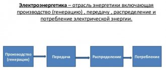
Electrical engineering
is a field of science and technology that studies electrical and magnetic phenomena and their use for practical purposes of obtaining, converting, transmitting and consuming electrical energy.
Electronics
is a field of science and technology that studies electrical and magnetic phenomena and their use for practical purposes of obtaining, converting, transmitting and consuming information.
Each science has its own terminology. Let's remember the terms and concepts of electrical engineering and electronics.
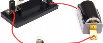
Electrical circuit
is a set of devices designed for the production, transmission, transformation and use of electric current.
All electrical devices according to their purpose, principle of operation and design can be divided into three large groups.
Energy sources, i.e. devices that produce electric current (generators, thermoelements, photocells, chemical elements).
Electromotive force
- electrical potential difference created by a source of electrical energy (electrochemical element, mechanical generator, thermoelement, photocell, etc.).
Receivers, or load, i.e. devices that consume electric current (electric motors, electric lamps, electrical mechanisms, etc.).
Conductors, as well as various switching equipment (switches, relays, contactors, etc.).
The directed movement of electric charges is called electric current. Electric current can occur in a closed electrical circuit. Electric current, the direction and magnitude of which are constant, is called direct current and is denoted by the capital letter I
.
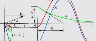
Electric current, the magnitude and direction of which does not remain constant, is called alternating current. The value of alternating current at the considered moment in time is called instantaneous and is denoted by the lowercase letter i
.
For an electrical circuit to operate, it is necessary to have energy sources. In any source, due to external forces of non-electric origin, an electromotive force is created. A potential difference or voltage arises at the source terminals, under the influence of which an electric current arises in the external part of the circuit connected to the source. There are active and passive circuits, sections and elements of circuits. Active circuits are electrical circuits that contain energy sources, while passive circuits are electrical circuits that do not contain energy sources.
Linear electrical circuit
- this is a circuit in which not a single parameter of the circuit depends on the magnitude or direction of the current or voltage.
Nonlinear electrical circuit
- this is an electrical circuit that contains at least one nonlinear element. The parameters of nonlinear elements depend on the magnitude or direction of current or voltage.
Electrical diagram
is a graphical representation of an electrical circuit that includes symbols of devices and shows the connection of these devices. In Fig. Figure 1.1 shows an electrical diagram of a circuit consisting of an energy source, electric lamps 1 and 2, and electric motor 3.
Rice. 1.1
To facilitate analysis, the electrical circuit is replaced by an equivalent circuit.
Substitution scheme
is a graphical representation of an electrical circuit using ideal elements, the parameters of which are the parameters of the replaced elements.
Figure 1.2 shows the equivalent circuit.
Rice. 1.2
Safety and Practice
When mastering an electrical engineering course for beginners, it is necessary to pay special attention to safety issues, since failure to comply with certain rules can lead to tragic consequences.
The first rule to follow is to read the instructions. All electrical appliances always have a section in their instruction manual that deals with safety issues.
Important! Following the recommendations will help avoid injury and damage to property.
The second rule is to monitor the condition of the conductor insulation. All wires must be covered with special materials that do not conduct electricity (dielectrics). If the insulating layer is damaged, first of all it should be restored, otherwise harm to health may occur. In addition, for safety reasons, work with wires and electrical equipment should only be done in special clothing that does not conduct electricity (rubber gloves and dielectric boots).
The third rule is to use only special devices to diagnose electrical network parameters. Under no circumstances should you do this with your bare hands or try it on your tongue.
Note! Neglect of these basic rules is the main cause of injuries and accidents in the work of electricians and electricians.
1.2. Passive equivalent circuit elements
The simplest passive elements of an equivalent circuit are resistance, inductance and capacitance. In a real circuit, not only the rheostat or resistor has electrical resistance, but also conductors, coils, capacitors, etc. A common property of all devices with resistance is the irreversible conversion of electrical energy into thermal energy. The thermal energy released in the resistance is usefully used or dissipated in space. In an equivalent circuit, in all cases where it is necessary to take into account the irreversible transformation of energy, resistance is switched on.
The conductor resistance is determined by the formula
(1.1)
where l is the length of the conductor; S—section; ρ is resistivity.
Conductivity
is the reciprocal of resistance.
Resistance is measured in ohms (Ohm), and conductivity is measured in siemens (Sm).
The resistance of the passive section of the circuit is generally determined by the formula
where P is power consumption; I - current. The resistance in the equivalent circuit is depicted as follows:
Inductance
- this is an ideal equivalent circuit element that characterizes the circuit’s ability to accumulate a magnetic field. It is believed that only inductive coils have inductance. The inductance of other elements of the electrical circuit is neglected.
The inductance of the coil, measured in henry [H], is determined by the formula
where W is the number of coil turns; F is the magnetic flux of the coil excited by current i.
The figure shows an image of inductance in an equivalent circuit.
Capacity
- this is an ideal element of an equivalent circuit that characterizes the ability of a section of an electrical circuit to accumulate an electric field. It is believed that only capacitors have capacitance. The capacitance of the remaining elements of the circuit is neglected.
The capacitance of the capacitor, measured in farads (F), is determined by the formula:
where q is the charge on the capacitor plates; Uc is the voltage across the capacitor.
The figure shows an image of a capacitance in an equivalent circuit
Electricity
Electric current (I) is the directed movement of free electric charge carriers.
In metals, free charge carriers are electrons; in plasmas and electrolytes, they are ions. The unit of current measurement is ampere (A). Conventionally, the positive direction of current in the external circuit is taken to be the direction from a positively charged electrode (+) to a negatively charged one (-).
Get a decision on TOE
If the direction of the current in the branch is unknown, then it is chosen arbitrarily. If, as a result of calculating the circuit mode, the current has a negative value, then the actual direction of the current is opposite to the arbitrarily chosen one.
Active equivalent circuit elements
Any energy source can be represented as an EMF source or a current source. An EMF source is a source characterized by electromotive force and internal resistance. An ideal EMF source is one whose internal resistance is zero.
In Fig. Figure 1.3 shows an EMF source, to the terminals of which a resistance R is connected. Ri is the internal resistance of the EMF source. The EMF arrow is directed from the point of the lowest potential to the point of the highest potential, the voltage arrow at the terminals of the source U12 is directed in the opposite direction from the point with a high potential to a point with a lower potential.
Rice. 1.3
Current
(1.2)
(1.3)
An ideal EMF source has internal resistance Ri = 0, U12 = E. From formula (1.3) it is clear that the voltage at the terminals of a real EMF source decreases with increasing current. In an ideal source, the terminal voltage does not depend on the current and is equal to the electromotive force. Another way to idealize the source is possible: representing it as a current source. A current source is an energy source characterized by an almost constant current value and low internal conductivity.
An ideal current source is one whose internal conductivity is zero and whose resistance is infinity.
Let's divide the left and right sides of equation (1.2) by Ri and get
,
where is the current of the current source;
- internal conductivity.
An ideal current source has gi = 0 and J = I.
The current of an ideal source does not depend on the resistance of the external part of the circuit. It remains constant regardless of the load resistance. A conventional image of a current source is shown in Fig. 1.4.
Any real EMF source can be converted into a current source and vice versa. An energy source whose internal resistance is small compared to the load resistance approaches in its properties an ideal EMF source.
Rice. 1.4
If the internal resistance of the source is large compared to the resistance of the external circuit, it approaches in its properties an ideal current source.
1.4.Basic definitions related to schemes
There are branched and unbranched circuits. In Fig. Figure 1.5 shows an unbranched diagram. In Fig. Figure 1.6 shows a branched circuit containing two EMF sources and 5 resistances. The resistance of the connecting wires is assumed to be zero.
A branch circuit is a complex combination of connections between passive and active elements. In Fig. Figure 1.6 shows a branched circuit containing two EMF sources and 5 resistances. The resistance of the connecting wires is assumed to be zero.
Rice. 1.5
Branch
- this is a section of an electrical circuit through which the same current passes.
node
- this is the junction of three or more branches of an electrical circuit.
A node at which two branches converge is called removable, that is, topologically it is not a node. A topological, real or irreducible node is one in which three or more branches are connected. A node in the diagram is indicated by a dot.
A series connection is a connection of sections of a circuit in which the same current passes through all sections. In a parallel connection, all sections of the circuit are connected to one pair of nodes and are under the same voltage. Any closed path that includes several branches is called a circuit.
Rice. 1.6
Ohm's law
This law relates to the basic provisions and concepts of electrical engineering. It most accurately reflects the relationship between quantities such as current, voltage, resistance and power. The definitions of these quantities have already been considered; now it is necessary to establish the degree of their interaction and influence on each other.
In order to calculate this or that value, you must use the following formulas:
- Current strength: I = U/R (amps).
- Voltage: U = I x R (volts).
- Resistance: R = U/I (ohm).
The dependence of these quantities, for a better understanding of the essence of the processes, is often compared with hydraulic characteristics. For example, at the bottom of a tank filled with water, a valve with a pipe adjacent to it is installed. When the valve opens, water begins to flow because there is a difference between the high pressure at the beginning of the pipe and the low pressure at the end. Exactly the same situation occurs at the ends of the conductor in the form of a potential difference - voltage, under the influence of which electrons move along the conductor. Thus, by analogy, voltage is a kind of electrical pressure.
The current strength can be compared with the water flow, that is, the amount of water flowing through the cross-section of the pipe over a set period of time. As the pipe diameter decreases, the water flow will also decrease due to increased resistance. This limited flow can be compared to the electrical resistance of a conductor, which keeps the flow of electrons within certain limits. The interaction of current, voltage and resistance is similar to hydraulic characteristics: with a change in one parameter, all the others change.
1.5. Operating modes of electrical circuits
Depending on the load, the following operating modes are distinguished: nominal, no-load, short-circuit, coordinated mode. In nominal mode, electrical devices operate under the conditions specified in the manufacturer’s data sheets. Under normal conditions, current, voltage, and power values do not exceed the specified values. Idle mode occurs when the circuit is broken or the load resistance is disconnected. The idle mode is an emergency mode for current sources. Short circuit mode occurs when the load resistance is zero. The short circuit current is several times higher than the rated current. Short circuit mode is an emergency for voltage sources. Matched mode is the mode of transmission from the source to the load resistance of the highest power. The matched mode occurs when the load resistance becomes equal to the internal resistance of the source. In this case, maximum power is released into the load.