The inevitable material and financial losses that result from the failure of a cable line (CL) force us to look for the most effective ways to eliminate damage that minimize these losses. The correct choice of method and equipment for searching for damage sites determines the effectiveness of solving the problem, i.e. the maximum probability of correctly identifying the location of the damage and the minimum time spent on this. The causes of defects in cables are very diverse. The main ones are: mechanical or corrosion damage, manufacturing defects, defects in the installation of connecting and end couplings, drying out of the insulation due to local overheating of the cable and aging of the insulation.
Types of damage and basic search methods
| Types of damage | Damage diagram | Transition resistance, Ohm | Remote method | Topographic method | Equipment for identifying damage locations |
| Phase short circuit to cable sheath | Rп | Pulse | Acoustic | REIS-105M1, GP-24 “Acoustic”, PA-1000A | |
| 100 4 | Mostovoy | Acoustic, overhead frame | REIS-305, SC40, PKM-105, GP-24 “Acoustic”, PA-1000A | ||
| Rп ≤ 50 | Pulse | Acoustic, induction, overhead frame | REIS-105M1, KP-500K | ||
| 100 4 | Loop (bridge) | Acoustic | REIS-305, SC40, PKM-105, GP-24 “Acoustic”, PA-1000A | ||
| Rп ≤ 50 | Pulse | Acoustic | REIS-105M1, KP-500K | ||
| 100 4 | Mostovoy | Acoustic, induction | REIS-305, SC40, PKM-105, GP-24 “Acoustic”, PA-1000A | ||
| Short circuits between phases | Rп | Pulse | Induction | REIS-105M1, KP-500K | |
| Broken wire with grounding and without grounding | Rп > 106 | Pulse, oscillatory discharge | Acoustic, induction, overhead frame | REIS-305, SC40, SDC50, SD80, AIP-70, GP-24 “Acoustic”, PA-1000A, KP-500K | |
| Rп > 106 | Pulse, oscillatory discharge | Acoustic | REIS-305, SC40, SDC50, SD80, AIP-70, GP-24 “Acoustic”, PA-1000A | ||
| 0 Rп 3 | Pulse | Acoustic, induction | REIS-105M1, GP-24 “Acoustic”, PA-1000A, KP-500K | ||
| Floating breakdown | Rп > 106 | Oscillatory discharge | Acoustic | REIS-305, SC40, SD80, AIP-70, GP-24 “Acoustic”, PA-1000A |
General principle
The potential difference is created by distributed currents flowing in the soil volume, which in turn are induced by the electromagnetic field around the communication or arise as leakage currents in the MP insulation, where a galvanic connection with the soil is formed. Direct current and alternating current of high frequency (sound range) are used. The magnitude of the measured voltage and the nature of its change along the communication are informative parameters for MF localization. The operator moves along a track with two contact rods or plates (A-frame). In the first case, the potential difference is directly measured, in the second - through the capacitance of the plates. The plates are used for asphalt concrete pavements on the KL highway. Current is supplied to the damaged core from the end of the cable line. The A-frame (AR-500), developed by , is used in conjunction with the PP-500A Search Receiver from the Search Kits.
Distance (relative) methods
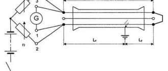
- The pulse method is that electrical pulses (probing pulses) are sent into the cable line, which, propagating along the line, are partially reflected from the inhomogeneities of the wave impedance and return to the place from which they were sent. Using the time it takes for the pulse to travel to the inhomogeneity and back, which is proportional to the distance to it, the distance is calculated. You can determine the distance to the place of damage, wire breakage, cable length. You can determine the distances to inhomogeneities, couplings, single-phase and interphase cable damage.
- The capacitive method
can be used when cable cores are broken. The distance to the break point is determined by the value of the measured capacitance of the cable conductors. The measurement is carried out using AC bridges. AC bridges can be used to measure capacitance during breaks with an insulation resistance at the point of damage of at least 300 Ohms. At lower resistances, the measurement accuracy drops below the permissible value. - The oscillatory discharge method
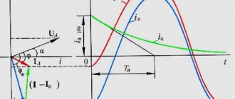
is used to determine the distance to places of single-phase faults with a transition resistance at the fault site of the order of 10-100 kilo-ohms. Using a high-voltage testing machine, the voltage on the damaged cable core is raised to the point of breakdown. A short circuit in a charged cable core results in the appearance of electromagnetic waves that propagate from the point of breakdown at the defect site to the beginning and end of the cable line. By analyzing the voltage diagrams of the oscillatory process, you can calculate the distance to the defect. - The wave method
is used if the resistance at the damage site is from zero to hundreds of kilo-ohms. The method is implemented as follows. When the spark gap of a high-voltage rectifier installation breaks down, a high-voltage electromagnetic wave from a charged capacitor is sent into the line, which creates a breakdown at the site of damage to the cable line, which causes a wave oscillatory process in the capacitor-line circuit. When an electromagnetic wave sent from a capacitor reaches the place of damage, a breakdown will occur if the resistance at the place of damage is not zero Ohm, after which the wave front reflected from the damage will return to the place of sending - the capacitor, will be reflected from it and return to the place of damage. If the resistance at the damage site is close to zero, the discharge will not occur and the wave will be reflected from the short circuit. This process will continue until the wave dies out. By measuring the time dependence of the voltage at the cable terminals during the oscillatory process, it is possible to establish the time during which the wave reaches the breakdown site and calculate the distance to it. - The loop method
is based on measuring the current resistance of the cable cores (usually using a bridge). Used to determine the location of damage to protective plastic insulation. The accuracy of determining the distance to the damage site is low and amounts to about 15% of the measured length.
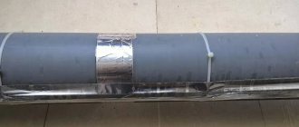
Opening a dead-end coupling
The photo shows a dead-end coupling MT-45. Designed to protect splices of TPP and TPPep cables with a capacity of 10 to 50 pairs with conductors with a diameter of 0.32 to 0.5 mm. The coupling consists only of a polyethylene body in the form of a polyethylene tube, plugged on one side. The method of installing TPP and TPPep cables in the MT-45 coupling consists of connecting the cores and screens of the parallel connected ends of the cables, placing them in the coupling body and then filling the coupling with self-expanding polyurethane sealant VILAD-31. It’s just that it was clearly installed without the use of VILAD-31 sealant, but with the help of an incomprehensible white mass, more like soap or grease. And, of course, blue electrical tape. It is known that in any unclear situation you should use blue electrical tape - this is the “key to success.” The result of such installation of a coupling connection is in front of you.
Topographic (absolute) methods
- The acoustic search method
is based on listening above the damage site to sound vibrations that arise at the damage site at the moment of a spark discharge from electrical impulses sent into the cable line. - A potential search method
is based on fixing on the ground surface along the path of electrical potentials created by currents flowing through the CL shell in the ground. - The induction search method
is based on monitoring the magnetic field around the cable, which is created by the current flowing through it from a specialized generator. By assessing the level of the magnetic field, the presence of CL and the depth of its occurrence are determined, and the location of the damage is determined by the nature of the change and the level of the field. This method is used to directly find places of damage on the cable in the event of a breakdown of insulation between the cores or to the ground, a break with a simultaneous breakdown of the insulation between the cores or to the ground, to determine the cable route and its depth, to determine the location of the couplings.
Causes of damage
The main reasons are as follows:
- design errors (underestimation of cross-section, incorrect selection of protective equipment);
- defects made during production: through holes, cracks and burrs on the wire;
- sharp bends and mechanical breakdowns caused during cable laying;
- damage caused during operation: aging of insulation, corrosion of metals, ruptures during excavation work
Depending on the type of cable laid, the method of its installation and the voltage level, the method used to locate the damaged area is selected. The main, most effective ways to determine the location of the fault are the methods discussed below.
Let's consider the main properties and characteristics required for search equipment
- High receiver selectivity. This parameter will provide electrical noise immunity, allowing you to successfully conduct a search in the presence of powerful sources of regular interference.
- High receiver sensitivity. Combined with high selectivity, it will ensure the search for communications with a weak signal at great depths.
- Quality and temporal stability of the generator output signal. This will provide both the necessary selectivity and sufficient noise immunity. In addition, the generator signal will not affect the operation of other electronic equipment.
- The generator output power is sufficiently large, allowing it to operate on deep (up to 10 meters) buried and long (up to several tens of kilometers) cable lines. This requirement is absolutely necessary for Russian conditions. It is also possible to use a powerful and reliable generator with a large output current as a cable afterburning device.
- High reliability of the generator, providing unlimited operating time for active and reactive loads in the range from short circuit to idle with possible sudden changes in magnitude.
- High performance characteristics. Minimum operating temperature range: from -30 °C to +40 °C.
- A sufficient set of operating frequencies of the generator and frequency channels of the receiver, ensuring guaranteed performance of the functions of route search and determination of fault locations.
- Versatility, i.e. the ability to work using induction, acoustic and potential methods. A desirable property that allows you to minimize the required set of equipment.
All the above properties and characteristics allow for maximum efficiency, i.e. with minimal expenditure of time, money and guaranteed results, search for places of damage to cable lines.
Nowadays, searching for the location of cable damage is carried out using modern search kits. Professional search kits, such as, for example, KP-500K, KP-250K and KP-100K, allow you to search for a defect location and determine the depth of the cable in the shortest possible time.
Finding the break point
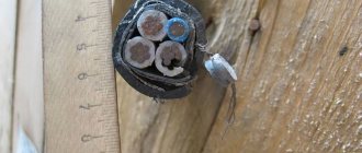
With the help of such homemade devices, you can find the location of a hidden wiring break. If a contact break is detected, the device will stop beeping, the nature of the noise will change, or the indicator light will go out. However, these devices have one significant drawback: cable detection is impossible if the hidden wiring is located at a depth of more than 5 cm.
But if fittings or other metal elements pass through the wall, then detecting hidden cables becomes difficult, because false signals will appear. This needs to be taken into account.
For the most accurate search for a broken hidden wiring, finders are used that have the possibility of additional settings, which allows you to ignore large metal objects in the wall. This function eliminates the sending of false signals. If there is direct access to the entire length of the wiring, then the damaged area is often visible to the naked eye. In the case where there is no visible damage, searching for the location of the electrical wiring break can be done using a conventional tester. The algorithm of actions will be as follows:
- first of all, it is necessary to de-energize the room by turning off the electricity supply in the electrical panel;
- then you need to strip the wire in two places: at the outlet of the distribution block and at a distance of 1 meter from the notch made;
- on this segment the resistance is measured, then another notch is made after 1 meter and the procedure is repeated;
- The resistance at all measured intervals must be the same. When the device finds an area where the value is very different or completely absent, a break occurs in this place.
If it is not possible to buy a special finder, but there is a great desire to solve the problem without outside help, you can assemble a primitive device for searching for broken wiring with your own hands.
All you need is a working socket, a light bulb, two single-core wires, a knife, pliers and electrical tape.
A light bulb is screwed into the socket and the wires are connected. From the other ends, the insulating material is stripped 4-5 mm from the edge.
Detecting a wire break involves connecting the tester to the wire being tested, which must be cut with a knife (before stripping the cable, you must turn off the power supply).
https://youtube.com/watch?v=zNSVKAwadZw
If you find an area where the light on the tester does not light up, you need to start moving in the opposite direction, making notches at a shorter distance. After finding the desired location, the damaged section of the wiring will be replaced, all cuts made must be insulated.
It is advisable to find out the location of hidden wiring and draw up a detailed diagram before a break occurs. This will protect the cables from damage during repair work. If you accidentally get into hidden electrical wiring, at best the room will be de-energized, at worst it will cause harm to human health.
Finding the location of the 10 kV cable damage
You can order a service to locate a damaged cable (cable line) and find out prices by calling or calling:
- 8(916)599-3477 in Moscow and the region.
- 8(499)-398-2030 in Tula, Kaluga, Ryazan and the Central Federal District.
Prices for searching for cable line damage (with subsequent repairs):
- Comprehensive repair of 0.4 kV cable lines (basic): search for problem areas, excavation work associated with digging out the damage site, cable repair (installation of couplings, cable insertion if necessary), cable testing with issuance of a protocol. – from 35,000 rub.
- Determination of cable damage and short circuit on the cable (up to 1 km) 6-10 kV - from 16,000 rub.
- Search for breaks and short circuits on 0.4 kV cable – from 15,000 rub.
Briefly about cable line repair
Repair work on cable lines is usually classified into planned and emergency. As for the volume of such work, for the former it is, as a rule, capital, for the latter it is current.
During major works, planned replacement of cable lines, laying of new routes, etc. are carried out. If necessary, repairs and/or upgrades of related equipment are also performed. The latter include ventilation systems and lighting for cable tunnels, as well as pumps for pumping out groundwater. Considering the specifics of planned work, localization of defective areas is not required during their implementation.
The situation is completely different during emergency repairs. In order not to dig up the entire route, you should accurately determine the location of the wire break, insulation breakdown, etc. For this purpose, various methods are used, for which special equipment is used. This will be discussed in detail below.
Finding a broken hidden wiring in a concrete wall
A special device - a locator - will help you find the location of a wire break in a concrete wall. It is a combination of a receiver and an oscillator. This method can be associated with the induction method in searching for cable faults underground.
So, determining the location of the break with a route finder is not difficult. The end of the wire in which there is a break is connected to a generator, which sends pulses of a certain frequency into it. By passing the frame over the place where the wiring is laid, the sound that is formed as a result of the influence of impulses will be clearly audible in the headphones. As soon as the sound disappears, mark this place on the wall - this will be the point of damage to the wire.
Determining the location of damage (OMP) of a 6-10 kV cable
Damage to a
6 (10) kV cable is one of the most common damages in the cable industry of a city or large enterprise.
6-10 kV networks are very worn out, many cables have already exhausted their service life (more than 25 years) and damage to them is becoming more and more frequent. There may be several reasons why a cable line fails: mechanical damage, damage as a result of poor-quality cable installation, damage due to improper testing of cable lines, damage due to destructive methods of searching for short circuits on the cable. uses only non-destructive (non-burning) methods to locate damage to
6-10 kV cables. Our mobile electrical laboratories use modern equipment from the German concern SebaKMT.
In order to extend the life of worn-out cable lines and not accelerate the aging and destruction of the insulation of new cable lines, it is necessary to choose non-destructive methods of testing and searching for locations of damage on cables. When using burning installations to search for damage to cable lines with impregnated paper insulation, not only the location of the defect being sought is damaged, but also the connecting couplings along the length of the cable. Such a cable is then difficult to put into operation, since after repair during testing the cable fails again and this can continue for a very long time.
Electrical laboratory "PKB "REM"
uses the latest methods for preliminary localization of damage sites, which do not require reducing (burning) the contact resistance at the defect site. (Fig. 1)
To determine the nature of cable damage, you should:
- measure the insulation resistance of each conductor with respect to ground;
- determine the integrity (absence of breakage) of current-carrying conductors;
- if necessary, clarify the nature of the damage and check the length of the damaged cable cores.
Insulation resistance is measured with a megohmmeter for a voltage of 2500 V. The measurement results in order to establish the nature of the damage must be entered into the WMD protocol and used to select WMD methods and technology.
Methods for determining cable damage
After determining the nature of the cable damage, the method most suitable for determining the location of the damage in this particular case is selected. It is recommended to first determine the area within which the damage is located. The damage zone is determined using one of the following relative methods: ARM, ICE, Decay
After determining the damage zone, the location of the damage is determined directly on the cable line route using one of the following absolute methods:
- Induction
- Acoustic
To accurately determine the location of damage, as a rule, a combination of relative and absolute methods is used. Determining the location of damage is a labor-intensive process and requires certain skills and abilities from the electrical laboratory meter.
will be happy to help you determine the location of damage to 6 (10) kV cable lines with an accuracy of several centimeters in a short time!