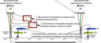
Loop method.
The loop method is used only when determining the distance to the short circuit of one or two cores relative to the shell with a transient resistance to direct current at the point of damage of no more than 5 kOhm and in the presence of at least one undamaged core. The method is based on the principle of a DC measuring bridge (see Fig. 14).
Measurements are made using a sensitive cable bridge, for example R-333, R-336, etc.
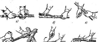
To carry out measurements, the damaged and undamaged conductors at the opposite end are connected with a jumper made of stranded copper wire with a cross-section of at least 50 mm, to the ends of which brass clamps are soldered. The bridge is connected to the cable cores (clamps 2, 3) with a flexible copper wire with a cross-section of 4 mm2 and brass clamps.
The arms of the measuring bridge are formed by adjustable resistances r1 and r2, resistances of the cores rx and r2, respectively, proportional to the cable lengths Lx and L+L y. By adjusting resistances r1 and r2, the galvanometer needle is set to the zero position, which corresponds to the balance of the bridge arms
The distance to the point of cable damage is determined by the formula
After determining Lx, it is necessary to swap the ends of the wires going to the cable and re-measure. In this case, the distance L+Lу is determined. If the sum of the results obtained differs significantly from the double length of the cable, then the measurements must be repeated, having first checked all contacts.
To increase the accuracy of determining the distance to the location of the fault, it is recommended to take measurements from one (1) and the other (2) ends of the cable. The accuracy of the measurements taken can be assessed by the relation
The sensitivity of the bridge and, therefore, the accuracy of the measurement depends on the ratio of the bridge supply voltage to the transient insulation resistance at the fault location. Therefore, the bridge supply voltage should be 100-120, 25-30 and 4-6 V with transition resistance values of 5, 1 and 0.1 kOhm, respectively.
During measurements, situations are possible when the bridge is not balanced. This is possible in cases where the damage is located at the very beginning of the cable on the measurement side, most often in the end cutting of the cable, as well as when the connecting wires are broken.
The formulas presented above are valid for homogeneous lines. If the line has different sections and the material of the cores, after measurements it is necessary to clarify the distance to the place of damage by reducing the lengths of the sections to any one section S and resistivity ρ
where Lpr(i), ρ(i), S(i) are the length, resistivity and cross-section of the i-th section of the line, respectively.
The reduced distance to the place of damage is determined through the reduced length of the line and the resistance of the arms of the measuring bridge when it is in equilibrium
The actual distance to the damage site is determined from Lxpr by recalculating to the actual S(i) and p(i).
When using DC resistance bridges, the loop method allows you to determine the distance to the location of cable damage with an accuracy of 0.1 - 0.3%.
Methods for determining cable damage in the ground
As a rule, cable flaw detection is carried out in two stages:
- The boundaries of the zone within which the emergency area is located are established.
- A search is made for the exact location of the damage in a certain area.
Accordingly, at the first stage, relative methods are used, and at the second stage, technologies with increased accuracy of damage detection are widely used. Let us list the main flaw detection techniques and the features of their application.
Induction method
This technology allows you to determine the location where the breakdown of the insulating layer of the conductive elements of the cable occurred. To do this, using a special generator, an alternating current with a power of up to 20.0 amperes and a frequency of 800.0 to 1200.0 hertz is supplied to the cable line. As a result, an electromagnetic field of a certain intensity is formed around the CL. If you place an antenna frame connected to headphones through an amplifier, you can hear a sound of a certain frequency above intact conductive elements.
By the nature of the sound signal, it is possible to determine not the location of the defect, the position of the couplings for connection, the topography of the route (tracing), including the presence of protective pipes. Below is a figure that shows the level of signal change over different sections of the cable line.
Finding cable faults using the induction method
Designations:
- Master oscillator.
- Location of connecting elements.
- Cable protection.
- Defective location.
Pulse method
As mentioned above, this method is relative, that is, it allows one to identify the defective damage zone (usually an interphase short circuit). The principle of operation is to apply a reference high-voltage pulse to the cable line using a special device and then determine the distance to the emergency area from the reflected pulse current signal.
Screen of the IKL device displaying the reflected pulse in the event of a short circuit (a) or a break (b) of the cable
In the example shown in the figure, the distance to the defective area is determined as follows:
tx – time interval between the sent and reflected electrical signal, measured in microseconds. As can be seen from the figure, it is equal to 3.5 μs. Considering that the pulse propagation speed (v) is approximately equal to 160.0 m/µs, then to solve it is necessary to apply the following formula: lx = ( tx*v ) / 2, where lx is the distance from the pulse generator to the damaged section of the cable. As a result, we get (3.5 * 160) / 2, that is, 280.0 meters.
Please note that in some devices the shape of the reflected signal can be used to judge the nature of the defect.
Acoustic method
The technology is based on the formation of spark discharges in the defective area, accompanied by sound pulses. You can fix them using a regular stethoscope, placing the acoustic head to the ground, or using a special acoustic receiver. Above the defective area, the sound frequency discharges will be as loud as possible.
Various schemes used in the acoustic method of searching for cable faults
Designations:
- Search for a stable short circuit between the current-carrying core and the cable sheath.
- Scheme for searching for floating breakdowns.
- The use of efficient conductive elements (the capacitance of the conductors is involved).
- Scheme for finding a cliff.
Video on the topic:
Capacitive method
The technology of this method allows you to search for damage, in particular a break in the current-carrying elements of the cable, by measuring the capacitance of the cores. As you know, this parameter directly depends on the length of the cable. A simplified circuit of high-voltage oscillations for such a device can be found below.
AC bridge used in capacitive cable fault detection method
Designations:
- R1, R2, R3 – adjustable resistors.
- Ce – standard high-voltage capacitor.
- L – distance to the break point.
- Lк – total length of the cable line.
- 1 – current-carrying elements of the cable.
- 2 – protective shell.
- 3 – break point.
By selecting the resistance of variable resistors, we achieve a minimum deviation of the arrow of the device G, which indicates balance between the arms of the bridge, which indicates the following ratio R1 / R2 = Cx / Se, this allows you to establish the capacitance of the damaged core Cx = Se * (R1 / R2).
In a similar way, we determine the capacitance at the other end of the cable line, that is, we connect a generator to it and repeat the measurements. As a result, we calculate the distance to the damaged area: L = Lk * C1 / ( C1 + C2 ), where C1 and C2 are the capacitances of the damaged current-carrying elements of the cable, measured at the beginning and end of the cable line.
Oscillatory discharge method
This method allows you to more effectively determine the distance to a cable defect, known as a floating breakdown. For this purpose, pulsed oscillatory discharges are applied to the damaged line, after which data on the distance to the defective location is displayed on the screen of a special device (for example, EMKS58).
Screen of the REIS-305 device indicating the distance to the damaged section of the cable
The operating principle of this method is in many ways reminiscent of the pulsed flaw detection method.
Loop method
This method works well in cases where there is no break in the current-carrying elements of the cable at the location of the insulation failure, and the transition resistance at the location of the defect is no more than 5.0 kOhm. If the last condition does not meet, the cable can be burned (burning the insulation to reduce the contact resistance). A simplified example circuit diagram for the loop method is shown below.
Capacitive method.
The method is used to determine the distance to the point of breakage of one or more wires of a cable line by measuring the cable capacitance. Measurements can be carried out either using an AC bridge (see Fig. 15) or using a DC ballistic galvanometer (see Fig. 16).
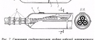
Rice. 15. Measuring diagram for determining the location of cable wire breaks using the capacitive method using a 1000 Hz AC bridge.
1 - cable cores; 2 - place of wire break; 3 - cable sheath; T - telephone.
It is recommended to carry out measurements on alternating current with a transient short circuit resistance of the cable fault location from 5 kOhm to 20 Megohm, and on direct current with a resistance above 20 Megohm.
Measurements on alternating current consist of measuring the capacitance of the cable section to the point of breakage C x using a 1000 Hz alternating current bridge (for example, p-565). The arms of the measuring bridge are formed by unregulated resistances r1 and r4, adjustable resistance r2, adjustable reference capacitance Cet and the capacitance of the measured core Cx. The balance of the bridge is established by rq and Seth and is checked by the absence of sound from the telephone T.
The distance to the place of damage is determined depending on the nature of the damage using one of the methods presented below.
Rice. 16. Measuring diagram for determining the location of a cable wire break using the capacitive method at direct current.
1 - cable cores; 2 - place of wire break; 3 - cable sheath.
- Wire rupture without grounding. Measure the capacitance of the damaged core from one end of the cable Cx(1), then from the opposite end Cx(2). The total length of the cable is divided in proportion to the resulting capacitances
- One of the parts of the broken wire has a short circuit to ground. The capacitance of the ungrounded part of the core C x and the capacitance of one undamaged core C are measured. The distance to the place of damage will be determined
- The capacitance of the core can be measured from one end, the remaining cores are shorted to ground. The capacitance of the ungrounded end of the broken wire Cx is measured. The distance to the place of damage is determined approximately by the specific capacitance of the cable core C 0 (see Table 17)
During measurements, the greatest accuracy will be ensured in the 1st case, in the 2nd case the measurement results are slightly overestimated, case 3 is appropriate for a cable length of up to 200 m.
Measuring direct current capacitance using a ballistic galvanometer is based on the fact that the latter's needle drop is proportional to the amount of electricity passing through the frame when charging or discharging the cable capacitance. When measuring, the shunt rsh sets the minimum sensitivity of the galvanometer G, and switch S2 is set to position 1. In this case, the charging current, flowing through the galvanometer into the cable capacitance, throws the arrow at the angle αx. The shunt increases sensitivity to obtain a clear measurement. The average value based on the results of 3–4 measurements of the angle αx is taken as the final result. Before each measurement, the capacitance is discharged by setting switch S2 to position 2. The measurement of αet on the reference capacitance is performed similarly with the position of the shunt resistance unchanged.
When measuring at direct current, cases similar to those discussed above are possible. The distance to the damage site is determined using the same ratios.
Methods for determining damage zones for cable lines
The choice of method for determining the location of cable damage depends on the nature of the damage, the location of installation and the contact resistance at the location of the damage. If the cable line is damaged, the zone (localization location) of the damage is approximately determined, and after that, the location of the damage on the route is specified using various methods. To more accurately determine the damage zone, it is advisable to perform a search from one end of the cable line using several methods. If this is not possible, a more accurate result is obtained by searching using one method from both ends of the cable.
To search for the damaged area use:
- insulation burning method (destructive method),
- impulse method;
- oscillatory discharge method;
- loop method;
- capacitive method.
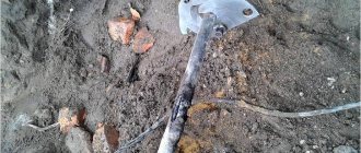
Insulation burning method . In this case, a place is established where the resistance between the conductors or between the conductor and the shell will be minimal. To clarify the location of the damage, it is necessary to reduce the contact resistance to the minimum limit. To do this, using a high-frequency generator or transformer, the insulation is burned. The burning process proceeds differently, depending on the nature of the damage and the condition of the cable. Usually after 15–20 s the resistance decreases to several tens of ohms. With moistened insulation, the process takes longer, and the resistance can only be reduced to 2000 - 3000 Ohms. In couplings, the process of burning the cable takes longer, sometimes several hours, and the resistance changes sharply: it decreases, then increases again, until the process is established and the resistance begins to decrease steadily. This is a destructive method for determining the location of cable damage.
The pulse method is used to determine the cable damage zone with a transient resistance of up to 150 Ohms in any cases except for a floating breakdown. The method is based on measuring the time interval between the moments of application of an alternating current probing pulse and the reception of the reflected pulse from the site of damage. The speed of propagation of pulses in high and low voltage cable lines is a constant value and is equal to V=160 m/µs.
Therefore, based on the travel time of the pulse to the point of damage and back (Tx), the distance to the point of cable damage (Lx, m) is determined:
Measurements are made with reflectometers (for example, REIS-105R). The device screen has a line of scale marks and a line of pulses. The shape of the reflected pulse can be used to judge the nature of the damage. The reflected impulse has a negative value in case of a short circuit, and a positive value in case of a wire break.
The oscillatory discharge method is used for floating breakdowns in cables. To measure, a voltage is applied to the damaged core from the test installation, which gradually rises to the breakdown voltage. At the moment of breakdown, an oscillatory discharge occurs in the cable. The period of oscillation determines the distance to the point of damage, since the electromagnetic wave propagates in the cable at a constant speed. Measurements are performed using reflectometers.
The loop method is based on measuring resistance using a DC bridge. The method can be used if one or two cable cores are damaged and if there is one undamaged core. If three cores are damaged, you can use a core of a nearby cable. To do this, the damaged core is short-circuited to the whole cable core, forming a loop. Adjustable bridge resistances are connected to the opposite ends of the cores.
The equilibrium of the bridge will be provided, p.u.:
The resistance of the cable core is directly proportional to its length, so the distance to the point of damage, m:
where R1 and R2 are adjustable bridge resistances, Ohms;
L – total line length, m.
The disadvantages of this method include greater time consumption, less accuracy, and the need to install short circuits. Therefore, the “loop” method is now being replaced by other methods: capacitive, pulsed methods, oscillatory discharge method and others.
Methods are constantly being improved.
The capacitance method is used to determine the distance from the end of the line to the point where one or more cable wires are broken by measuring the cable capacitance. The method is based on measuring the capacitance of a broken wire using an AC or DC bridge, since the cable capacitance depends on its length. If a cable core breaks without grounding, the capacitance of the broken wire is measured at both ends. We assume that the cable length is divided proportionally to the measured capacitances C1 and C2, then:
Once the damage zone is identified, an operator is dispatched to the area to locate the damage using acoustic, induction, or overhead frame techniques.
Acoustic method . The essence of the acoustic method is to create a spark discharge at the site of damage and listen along the path to sound vibrations caused by this discharge above the site of damage. This method is used to detect all types of damage on the route, provided that an electric discharge can be created at the damage site and this location is approximately known. For a stable discharge to occur, it is necessary that the value of the transition resistance at the damage site exceeds 40 Ohms.
The audibility of sound on the surface of the earth depends on the depth of the cable, the density of the soil, the type of damage and the power of the discharge pulse. The possible listening depth ranges from 1 to 5 m. It is not recommended to use this method for openly laid cables, cables laid in channels and tunnels, since due to the good propagation of sound along the metal sheath of the cable, a large error can be made in determining the location of damage .
A kenotron is used as a pulse generator with the additional inclusion of high-voltage capacitors and a ball gap in the circuit. Instead of capacitors, you can use the capacitance of undamaged cable cores. As an acoustic sensor, sensors of a piezomagnetic or electromagnetic system are used, which convert mechanical vibrations of the ground into electrical signals fed to the input of an audio frequency amplifier. The signal is greatest above the damage site.
The induction method is used to directly locate cable damage along the route:
- when the insulation is short-circuited, the cores are connected to each other or to the ground;
- in the event of a break with simultaneous breakdown of insulation between the conductors or on the ground;
- to determine the route and depth of the cable;
- to determine the location of couplings.
According to this method, changes in the electromagnetic field above the cable are recorded on the surface of the earth using a receiving frame when a current from fractions of an ampere to 20 A is passed through it (sound frequency 800÷1200 Hz). The range is determined depending on the presence of interference and the depth of the cable. The EMF induced in the frame depends on the current distribution in the cable and the relative spatial arrangement of the frame and the cable. Knowing the nature of the field change, it is possible to determine the route of passage and the location of cable damage by the orientation of the frame. More accurate results are obtained when current passes through the “core-core” circuit; for this, single-phase short circuits are converted to two- and three-phase by burning out, or an artificial “core-cable sheath” circuit is created, removing grounding from the circuit from both sides and connecting the generator to the core and cable sheath.
The field lines from the conductor-ground circuit current are concentric circles, the center of which is the cable axis. The current flowing through the forward and return wires creates two concentric magnetic fields acting in opposite directions (field from a pair of currents). When the cores are located in a horizontal plane, the resulting field on the earth's surface is greatest, and when the cores are located in a vertical plane, it is the smallest. Since the cables have twisted cores, an EMF will be induced in a frame located vertically and moved along the cable route, varying from a minimum with a vertical arrangement of the cores to a maximum with a horizontal arrangement of the cores. When searching for damage, you should remember that the signal behind the damage site fades at a distance of no more than half a step.
This method determines the cable route, the depth of its laying, and the location of the couplings (by amplifying the sound in the phone due to the increased distance between the cores). To determine the depth of the cable, first find the line of its route and draw a line. Then, positioning the frame axis at an angle of 45º to the vertical plane passing through the cable axis, the location of the disappearance of the induced EMF in the frame is established. The distance from this place to the route marked with a line is equal to the depth of the cable. In the presence of a protective metal pipe, the sound level decreases sharply, since the pipe acts as a screen.
The overhead frame method is used to directly detect the location of cable damage. The method is based on the same principle as induction and is convenient for open cable routing. When laying a cable in the ground, it is necessary to open several holes in the damaged area, after which a generator is connected to the core and sheath or between two cores. A frame is placed on the cable and rotated around its axis. To the point of damage, two maximums and two minimums of the signal from the field of a pair of currents will be heard. Behind the damage site, when the frame rotates, a monotonous signal will be heard, caused by the magnetic field of a single current.
Over the past 15 - 20 years, maintenance of underground telecommunications routes has become more difficult, because... There are more highways in use, their average age has increased, and construction work has intensified. In urban environments, there are problems with opening up the asphalt pavement and a high level of broad-spectrum electromagnetic interference.
Pulse method.
The pulse method is based on measuring the time tx of passage of an impulse from one end of the cable line to the place of damage and back, which, given the speed of propagation of this pulse h and the distance to the place of damage Lx, is determined by and , respectively. The speed of pulse propagation for most cables is 160±1 m/µs, respectively, the distance to the damage site can be estimated as Lх≈ 80·tх.
Based on this method, a series of devices of the type P5-5, P5-8, P5-9, P5-10 works, with the help of which you can find the location of the fault, starting from 1 m from the beginning of the line (P5-9) and a relatively large transition resistance in location of the ground fault (P5-8).
When the device is turned on, probing pulses are sent into the cable line, which, when passing through the cable, are reflected with a change in their amplitude values and signs in those places where the wave impedance differs from the wave impedance of the cable (35 Ohms). The more the resistance differs from the wave resistance, the greater the amplitude of the reflected pulse. Moreover, at the point of closure, the reflected impulse changes sign to the opposite. The amplitude and sign of the reflected pulse determine both the location of the damage and the nature of the damage. However, due to the presence of places of weakened cable insulation, inserts, couplings, etc., in which the resistance also differs from the wave resistance, the amplitudes of the reflected pulses can be comparable to the amplitudes of the reflected pulses from the damage sites, which complicates the identification of the location of the short circuit or break in the cable . So, for example, with the P5-5 device it is practically possible to identify a reflected pulse from the site of damage with a transition resistance not exceeding 4-5 times the value of the characteristic impedance of the cable, i.e. 150-200 Ohms.
Rice. 17. Screen of the cathode ray tube of the P5-5 device when determining the location of cable damage.
a) - checking the coincidence of the probing pulse with the zero scale mark; b) alignment of the reflected pulse (short circuit location) with the zero scale mark.
Probing and reflected pulses are displayed on the screen of the cathode ray tube. On the sweep of reflected pulses with an interval of 2 μs, scale time marks are applied (see Fig. 17). The travel time of the pulse from the damage site is determined by counting the calibrated time delay scale when combining the reflected pulse with the scale zero mark on the screen.
To obtain a still image on the screen, the process of supplying probing pulses and scanning the reflected pulses are periodically repeated with a frequency of 500-1000 Hz. The sweep is rigidly synchronized with the time of delivery of the probing pulse.
The measurement error on cable lines using these devices is quite high and does not exceed 1%.
Locating Cable Fault Location - 3 Proven Methods
- Short Circuit Damaged insulation results in a low-resistance short circuit between two or more conductors at the location of the fault.
- Earth fault/earth short circuit Faults can occur due to an earth fault (low-resistance connection to earth potential) of an inductively grounded network or an isolated network, and/or due to an earth short circuit of an earthed network. Another type of fault is a double ground fault, characterized by two ground faults on different conductors with separate origins.
- Cable breaks Mechanical damage and movement of the earth's surface can cause breaks in one or more conductors.
- Floating damage Often the damage is not stable, is episodic in nature and depends on the load on the cable. The cause may be drying out of oil-insulated cables under low load. Another reason is partial discharge due to aging or electrical treeing in polymer insulated cables.
- Damage to the cable sheath Damage to the outer cable sheath does not always lead to immediate failure of the cable line, but over time can cause damage to the cable, in particular due to moisture penetration and damage to the insulation.