Laying power cable lines
This type of work involves laying a power cable with the subsequent delivery of electricity from the power source to the consumer. Several types of cable laying are regulated:
- in the ground;
- in the sewer;
- according to established structures.
Laying cable lines consists of several rather labor-intensive steps. First of all, this is the development of the project, followed by preparation of the route, installation or excavation work, installation of the structure, laying of pipes, installation of auxiliary equipment, testing by certified laboratories and connection to the cable.
Our company provides all types of work from the development of design estimates to the installation and connection of internal and external networks of various voltages. Our specialists have extensive experience in carrying out work on laying power cables with subsequent commissioning activities at facilities of any complexity, while guaranteeing high-quality performance of work within the time limits specified in the contract. We have all types of permits and SRO certificates with permits for work with a high degree of impact on the safety of capital construction projects.
Installation of cable terminations and couplings.
The most difficult job when ducting electricity with cables is installing cable terminations and connections. In recent years, new methods of terminating and connecting cables have been developed and implemented, which have significantly increased the reliability of cable networks. Instead of the previously used end seals in steel funnels and with the help of keeper tape, seals with polyvinyl chloride tape, complete rubber gloves and epoxy are now used. These cable terminations are small in size, have the necessary dielectric and mechanical strength, resistance to mineral oils, moisture and heat resistance, less labor intensity and a number of other advantages.
The general requirement for all types of terminations and connections is to ensure the tightness of the cable insulation at the point where the current-carrying conductors exit to prevent moisture from penetrating into the cable.
The reliability of couplings and seals depends on careful installation, compliance with the technology specified in the installation instructions, and sanitary hygiene standards. The entry of moisture or dirt into the coupling or seal sharply worsens the electrical strength and leads to failure of the cable when tested after installation or during operation. Therefore, work on the installation of couplings and seals must be carried out with clean hands and tools, without interruption in work until they are completely completed. Before starting work, the clutch housing must also be thoroughly cleaned on both sides and wiped with rags soaked in gasoline. The application and technology of installation of couplings and seals are discussed in the “Technical documentation for couplings for power cables with paper and plastic insulation up to 35 kV”, therefore only general information and individual elements of installation of couplings and seals are given below.
Installation of terminations and couplings begins with installation operations called cutting the end of the cable, which consists of sequentially removing protective covers, armor, sheath and insulation of the cable over a certain length. The result is a stepped cutting, the size of the steps depends on the voltage, type and dimensions of couplings and terminations.
First, before cutting, check the paper insulation for the absence of moisture: tear off the paper strips from the end of the cable and dip them into paraffin heated to 140-150 ° C. When the insulation is wet, cracking and foaming are observed. The moistened insulation in an area of 250-300 mm is removed and checked again until positive results are obtained.
When cutting the end of the cable, a bandage (Fig. 2, a) made of two or three turns of galvanized steel wire is placed over the jute cover; unwind the cable yarn (Fig. 2, b) to the bandage and leave it to protect the armor from corrosion after installing the coupling (temporarily wrap it around the uncut part of the cable); apply a second bandage at a distance of 50-70 mm from the first (with connecting couplings of 100 mm); use the area between the two bands to connect the grounding conductor; cut the armor (Fig. 2, c) along the edge of the bandage and remove (Fig. 2, d) together with the pillow (Fig. 2, e); remove sulphate paper and bitumen composition (previously carefully heat it with a quick fire with a gas burner or blowtorch); wipe the lead or aluminum sheath with a rag soaked in gasoline or transformer oil heated to 40 °C in the area for soldering the grounding conductor and sealing the coupling neck; make two annular cuts in the lead or aluminum shell (Fig. 2, f) at a distance of 20 mm from each other and at a distance determined from the armor cut according to the technical documentation (with an aluminum shell, make a spiral cut, Fig. 101, j), make two longitudinal cuts shells (Fig. 2, g) at a distance of 10 mm from one another; remove a strip of the sheath (Fig. 2, h), and then the entire sheath (Fig. 2, i) from the end of the cable to the second cut (the sheath between both annular cuts is temporarily left to protect the belt insulation when bending the cores); bend the cores according to a template or manually with a bending radius of at least ten times the height of the sector or the diameter of the core along the insulation; bandage the core insulation at the cut point with two or three turns of cotton thread and remove the paper tapes, unwinding and removing them from the bandage; bend the lead sheath by flanging; After connecting or terminating the cores, the previously left annular shell belt is removed.
Rice. 2. Cutting a cable with paper insulation: a - applying a bandage over the jute cover on the cable, b - unwinding the outer jute cover, c - cutting the armor with an armor cutter, d - removing the armor, e - removing the cable yarn (cushion), f - making a ring cut sheath, g - making longitudinal cuts to the sheath, h - removing a strip of lead sheath, i - removing the entire sheath from the part of the cable to be cut, j - spiral cut of the aluminum sheath using an NKA knife with a cutting disk
Cable cutting with plastic insulation is carried out in the same sequence as with paper, stepwise removal of the hose, armor, cushions underneath, screens and insulation. Removed insulation is restored by insulating the joints and terminations with paper rolls and rollers, and more recently with self-adhesive tapes.
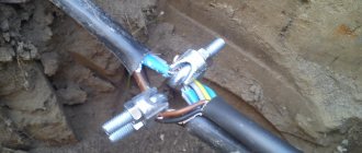
The connection of cables for voltages up to 1000 V is carried out, as a rule, in cast iron couplings, in which the main insulation is casting mastic, which is quite sufficient for low voltage while maintaining the insulating distances between the cores with porcelain spacers. The coupling housing SCh (SChm) consists of two halves connected by bolts. In the lower coupling half, there is a groove along the entire perimeter with a sealing gasket made of oil-resistant rubber or tarred hemp rope placed in it; in the upper coupling half, along the entire perimeter of the junction, there is a protrusion that fits into the groove of the lower coupling half. A resin tape is wound onto the cables at the points where they enter the coupling, which is crimped into the protrusions located in the neck of the coupling body.
Porcelain spacers are installed on the cores, one on each side of the connection point (closed PM - when connecting the cores by soldering and open P - when crimping or welding). In SChM couplings, instead of spacers, insulating windings are used on exposed areas of the cores. The spacers are fastened to the cores with cotton tape boiled in cable composition. The main insulation is a bitumen composition, poured in a heated form (up to 50-60 ° C) through holes in the upper half of the body in three or four stages to avoid the formation of shrinkage cavities and voids.
After the composition has cooled to ambient temperature, a gasket made of rubber or hemp rope is placed in the groove of the filling hole, the cover is secured with bolts and the joint seams, necks, couplings and bolts are covered with hot bitumen composition or varnish. The couplings are grounded with a copper stranded wire, which is connected at one end to the shells and armor tapes of each cable, and at the other (with a pressed or welded tip) to the contact pad (under the grounding bolt) in the lower half of the coupling. The connection of cables in a cast iron coupling is shown in Fig. 3, a, b. The connection of the cores in the coupling must ensure reliable contact, have low transition resistance and mechanical strength. The connection point must be free of sagging, burrs and other protruding parts, with a flat surface and smooth rounded transitions.
Rice. 3. Cast iron couplings: a - normal version MF, b - small-sized MF; 1,8 - upper and lower coupling halves, 2, 10 - windings made of resin and paper tapes, 3 - bandage, 4 - porcelain spacer, 5 - cover, 6 - tightening bolt, 7 - grounding conductor, 9 - connecting sleeve, 11 - plug, 12 — clamp
Connecting cables for voltages up to 1000 V is also carried out using epoxy couplings SE, PSSL, etc., which are produced in the form of ready-made kits having removable or non-removable rigid forms made of plastic or metal, filled in with an epoxy compound at the installation site.
The PSSL coupling made of self-adhesive tapes is designed for connecting cables with plastic insulation laid in the ground and cable structures. When cutting the ends, the plastic insulation of the cores is restored with self-adhesive tapes, and the plastic hose is restored with a heat-shrinkable tube using KO-916 varnish. The mounted coupling is placed in a protective plastic or metal casing.
To terminate cables for voltages up to 1000 V with paper insulation, it is recommended to terminate the internal installation with sealing of the cores with tubes of different designs: TV (heat-shrinkable), K (silicon-organic), N (made of nayrite rubber), T (three-layer plastic), as well as wearing rubber gloves and steel funnels. Recently, new seals have appeared based on self-adhesive KVsl tapes and in heat-shrinkable KVTp gloves.
End seal KVsl (Fig. 4) is intended for terminating paper-insulated cables for voltages of 1-6-10 kV with aluminum and copper conductors with a cross-section of up to 240 mm2 in dry rooms with a level difference of up to 10 m and is performed with self-adhesive tapes LETSAR (or LETSAR- LPt) and varnish KO-916, which have good adhesion to cable materials and high electrical characteristics. A variety of KVsl terminations are the end seals of the internal KVslt installation made of self-adhesive tapes and polyethylene heat-shrinkable tubes for paper-insulated cables for a voltage of 1000 V.
Rice. 4. Sealing of KVsl: 1 - layer of varnish KO-916, 2 - sealing winding with LETSAR tape, 3 - winding of cores with PVC tape, 4 - insulating winding of cores with LETSAR tape, 5 - bandage winding with LETSAR tape, 6, 7 - central and side sealing cone inserts
Termination in heat-shrinkable polyethylene gloves is used for terminating three-core (ZKVTp) and four-core (4KVTp) power cables with paper insulation up to 1000 V and consists of a heat-shrinkable polyethylene glove, to the fingers of which heat-shrinkable polyethylene tubes are glued to seal the cores. The tubes are sealed on the cylindrical part of the tip with heat-shrinkable polyethylene cuffs, and sealed in the lower part of the glove at the tips on the metal sheath of the cable with a special hot melt adhesive (GIPC-14-17), while the diameter of the tubes for cables with a cross-section of 16-240 mm2 is from 14/7 to 30/15 (the numerator indicates the internal diameter before shrinkage, the denominator indicates the internal diameter after shrinkage in a free state). The shrinkage of the tubes is carried out evenly by heating (gas burner flame) starting from the root of the embedment. After shrinking, the tubes should fit tightly around the cable cores (without wrinkles or folds).
The end seal in KVR rubber gloves has the same purpose as the KVTp seal, and consists of a rubber glove with nairite rubber tubes glued to the fingers to seal the conductors. The tubes capture the cylindrical part of the tips and are sealed on them with bands made of steel strips. The lower part of the glove is glued to the cable sheath and sealed with a clamp.
KVET seals with three-layer tubes consisting of a middle polyethylene, inner and outer polyvinyl chloride layers are installed in the same way as seals with nayrite tubes. At the lower end of the tube, only a polyethylene layer is left, which is processed with a file and coated with PED-B glue. Part of the outer polyvinyl chloride layer is also treated and lubricated with glue, which is then filled with epoxy compound. Seals with heat-shrinkable polyvinyl chloride tubes have the same purpose and application as seals with other tubes. The tubes, put on the tips, are seated with the flame of a gas burner, starting from their middle, first up and then down. After cooling, the tubes are sealed with LETSAR tape and coated with KO-916 varnish. The gap between the cut of the core insulation and the tubular part of the tip is filled by winding with LETSAR-L GTm tape (instead of the previously used winding of cotton tape with each layer coated with an epoxy compound). KVE epoxy terminations with Nairite rubber tubes on the cores are designed for terminating three-core power cables with impregnated paper insulation for voltages up to 10 kV. The plastic housing and coupling cover ensure guaranteed dimensions between the cable cores at the outlet, as well as between the cable cores and the housing. The new design increases the reliability of the couplings and their ease of installation.
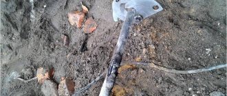
When making end seals in KVB steel funnels (rarely used), the funnel is put on the cable below the point where the conductors are routed (the root of the termination), sealed with several layers of insulating tape and filled with heated cable mastic. For winding, sticky polyvinyl chloride or polyethylene varnished fabric tape LKhM-105 is used with gluing with tsapon-glyphthalic varnish. Seals are carried out in oval (KVBo), round (KVBk) and oval small-sized (KVBm) funnels.
Seals in steel funnels are labor-intensive and not reliable enough in operation. If there is a difference in cable laying levels, the cable impregnating composition may leak out from the bottom seal. At high temperatures and ambient humidity, the seals absorb moisture, and at low temperatures, cracks appear in the bitumen mastic, through which moisture from the environment can penetrate into the cable. Other couplings and seals are used, given in the technical documentation, most of which are produced by manufacturers complete with parts and installation materials.
Issues covered
- What methods exist for laying cables across enterprises and production premises?
- Why are end seals and couplings installed on cables and what types of coupling designs exist for 1 kV cables?
19138
Bookmarks
Comment 2
Comments 2
Comment is being verified
The text of the comment will be visible after verification by the administrator.
December 11, 2022 at 12:00
Bookmarks
Cable laying in trays
Indoors, cables are laid along wall surfaces in boxes, cables, pipes and trays. From the point of view of installation and maintenance, the most convenient option is to lay the cable in electrical trays. This gives quick access to the cable for maintenance and repair work.
Electric trays produced today have an acceptable aesthetic appearance. To select the correct tray, take into account the cable cross-section and its weight. The tray is installed on special shelves on racks, secured with studs to the walls and ceiling. Our company’s specialists will select the best option for laying cables in trays, in accordance with the customer’s wishes and at the best prices.
Cable installation cost
The cost of cable installation depends on various factors. We carry out work inside buildings and premises. Internal cable routing differs from external cable routing in terms of execution principle and price. When carrying out electrical installation activities, we adhere to strict rules and act in accordance with the PUE.
| Name | Unit change | Price |
| Determining the location of cable line damage | 1 definition | 25 000,00 |
| Testing of 6-10 kV cable line | 1 line | 20 000,00 |
| Testing a 0.4 kV cable line | 1 line | 10 000,00 |
| Puncture/shot of cable line | 1 line | 5 000,00 |
| Definition of a cable line in a bundle | 1 line | 15 000,00 |
| Installation of 10 kV end coupling | 1 coupling | 12 500,00 |
| Installation of 1 kV end coupling | 1 coupling | 10 000,00 |
| Installation of 10 kV coupling | 1 coupling | 15 000,00 |
| Installation of 1 kV coupling | 1 coupling | 11 500,00 |
| Installation of adapter coupling | 1 coupling | 16 500,00 |
| Installation of a cable line in the ground | m.p. | 400,00 |
| Complex of earthworks (asphalt/concrete) | Pit – 7x1.5x1 | 40 000,00 further 3,500/m3 |
| Complex of earthworks (lawn) | Pit – 7x1.5x1 | 31 500,00 further 3,000/m3 |
| Opening of an Emergency Order for the right to carry out excavation works (work period up to 8 days) | Order | 60,000.00 — Moscow 40,000.00 – MO |
| Opening of the Notification of the Moscow Department (work period up to 2 months) | Notification | From 100,000.00 |
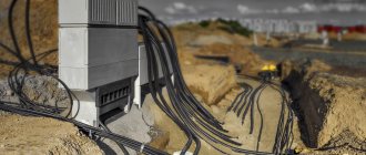
Laying cables in the ground
For external cable laying, a cable of the appropriate cross-section is selected based on the expected loads and power consumption of electricity. In a project for the power supply of a structure, a special section describes in detail the steps for laying the power cable.
Laying a power cable is a separate type of work with clearly defined regulations for each stage. The depth of the trench must be more than 70 cm. When laying several cables in one trench, a distance of 10 cm must be provided between them. If it is technologically necessary to lay the cable in a shallower trench, special protection is developed to prevent mechanical damage.
The route design is developed based on the shortest distance between connection objects, taking into account the best conditions for cable safety. When developing a route, designers take into account environmental conditions and the presence of other technical networks. It must be taken into account that in one trench there cannot be more than six cables with a voltage of up to 10 kW, and no more than two cables with a voltage of up to 35 kW.
Work on laying the power cable must be carried out by organizations that have the appropriate approvals and permits. Our company's employees have all the necessary permits.
Methods for laying hidden wiring in an apartment
Cable laying in a corrugated pipe
Before starting renovations in residential premises, you should first install new electrical wiring (if, of course, you plan to replace it). It is better to draw a diagram of the apartment in advance and outline the future rearrangement, determine the size and placement of furniture - such work can be entrusted to designers or done independently. After arranging the furniture, you should mark on the plan the installation locations of electrical connectors and switches. It is also recommended to consider the locations of spare sockets.
A certain difficulty is caused by wall lighting fixtures attached near bedside tables near the beds, because they are inextricably linked with the location of the beds. To connect the lamp in the area where the wires exit, it is best to mount a small installation box into the wall. When wallpapering, you can hide the cable under it.
It is quite difficult to install sockets in the cooking room. Installation should not be undertaken at all until the kitchen furniture has been ordered. Once the parameters of the furniture pieces are known, you can begin wiring.
In order to connect built-in kitchen and household appliances, electrical connectors are installed along the baseboards, 2–3 cm from the floor covering. Cover the wire with a removable bottom panel. At the same time, it is necessary to ensure free access to it.
According to the set of rules for design and construction SP 31-110-2003 “Design and installation of electrical installations of residential and public buildings”, in the premises there must be several sockets installed every 4 m of the perimeter of the room, in corridors - sockets are installed every 10 m of the corridor area. Kitchens are equipped with four or two double sockets.
It is necessary to correctly select the optimal routes for laying electrical wiring. The best cable track is one that has a minimum length, which makes it possible to lay the cable in a pipe. The connection terminal boxes must also be accessible.
If it is necessary to fill the screed, then the outlet network is best hidden in pipes along the floor, which can be corrugated from polyvinyl chloride or low-pressure polyethylene. The pipes must be firmly installed in the floor. After laying work, a pipe laying diagram with precise references is drawn up. A plywood sheet is laid on top of the screed. To protect electrical wiring from damage, when installing plywood you should:
- Lay the plywood on the floor;
- Draw a pipe laying diagram on a plywood sheet;
- Fix the building material to the cement-sand layer, avoiding drilling holes in the floor near the pipes;
- Before laying the flooring, inspect the electrical wiring for defects.
Due to the fact that wooden floors are not fire-resistant, electrical wiring under timber floors is laid in metal pipes.
It is recommended to lay electrical wiring to the lamps in the voids of the ceilings. In suspended ceilings, the wiring is laid in the space located behind the ceiling.
It is important to know!
It is not recommended to install the cable at the junction of two building structures. If one structure is displaced relative to another by a few millimeters, the cable will be damaged.
Laying power cables in tunnels
In the presence of unfavorable geodetic or natural conditions, power cables are laid in pipes and tunnels. The same work is carried out when laying the cable if it is expected to intersect with other communications or in aggressive soils.
Modern technologies make it possible to carry out horizontal directional drilling, which makes it possible to lay cables without opening the ground.
Cable line design
When designing cable lines, it is necessary to take into account the features of the network, the characteristics of the relief, the results of geodetic studies, the conditions for their further use and much more. Designers must receive a clear technical specification containing the wishes of the customer and the requirements for the project of land owners. As a result, the Customer receives a package of documents, which includes: a single-line diagram of the electrical network, diagrams of the intersection of the line with engineering systems, a route plan on the required scale, an explanatory note from the designers, and a situational plan.
We prepare design and estimate documentation and the entire range of works, allowing the customer to significantly reduce the cost of providing electricity to their facility. The costs of laying power cables are based on project cost calculations. The calculation also includes the collection and generation of permits for all types of work, excavation work, the cost of the cable, the cost of geodetic work and construction of the cable line. Next, all work related to laying, protecting and covering cable networks from possible accidental damage is taken into account. It is important to carefully consider the calculations for landscaping the surrounding area and restoring the removed coatings during the work.
By contacting our specialists, you can not only competently carry out all stages of work on laying cable lines in Moscow, but also save a lot of money on obtaining permits, conducting laboratory tests, etc.
Overhead line support
Overhead power lines and low-current networks are also installed on supports. Supports are classified by material and type.
Supports, pillars and masts of overhead cable lines according to material are divided into:
- wooden;
- reinforced concrete;
- metal.
Please note that according to regulations, metal supports are only allowed to be used in overhead cable lines with voltages over 1 kV.
Supports, pillars and masts of overhead cable lines are divided by type into:
- Intermediate. An intermediate support is a single pole that is placed in very long spans where the sagging of the cable under its own weight can pose a risk of breakage.
- Anchor. Installed on transitions, providing additional structural strength.
- Angular. They are installed at turns in the overhead cable line route, which prevents the formation of bends and kinks in the cable.
- A-shaped. Such supports are installed in places where wires are soldered to install arresters. A surge arrester is a device designed to limit overvoltages in electrical networks.
When laying overhead cable lines using supports, some temporary structures are allowed. An example is a hanging of non-galvanized single-core wires. Such wires are secured to supports on pin insulators using wire ties or special clamps. The connection of the wires can be anything - from thermite welding. The wires are connected with special connecting clamps, electric contact or thermite welding, depending on their type. Wires on high-voltage lines are usually aluminum, steel/aluminum or pure steel. They are secured to pin or suspension insulators (garlands) of overhead cable lines with supporting and tension locks.