Power cables play a very important role in the system of ensuring uninterrupted power supply to machines and devices. Many cable lines have a service life of several decades, which means they are subject to a higher failure rate. For this reason, it is necessary to replace worn cable lines, first of all, in the worst technical condition. But first of all, determine why the cable damage occurred.
Taking into account the above statements, it is very important to correctly assess the condition of the cable, as well as identify areas that are especially at risk of failure. A power outage can cause production losses and threats due to the lack of power supply to key facilities and the most important economic structures of a city, province or even the entire country. The above considerations make the issue of correct assessment of the technical condition of the cable line relevant. This assessment should be based on diagnostic tests that can detect and isolate defects that may soon lead to failure. It is necessary to know the mechanisms that lead to degradation of cable insulation, the effects of this aging, and location techniques to locate weak spots.
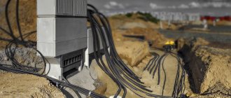
For operation in macroclimatic regions with temperate and cold climates, as well as for laying electrical communications in earthen trenches, the ASBl-6 3x150 cable is used - an armored conductor with sufficient protection from possible atmospheric, compression and mechanical influences. Taken from here: Complex supply of cable and wire products and fittings KompleksEnergo.
Cable damage - causes
The main factors causing damage to cable lines include:
- electrical factors such as overvoltages, electrical and electrostatic discharges, overloads or incorrect measurements of insulation properties;
- damage caused by improper cable manufacturing quality, mainly defects in the design of cables, cores or insulation;
- the influence of external environmental factors on the cable in use, including the influence of variable temperature and climatic conditions, dust, moisture and all chemical factors;
- damage caused by overuse, which may include degradation and aging of insulation, as well as chemical transformation processes affecting the used cable;
- atmospheric factors, such as precipitation, the general humidity of the ground on which the cable operates, wind, lightning strikes or the magnetic effects of solar storms;
- other factors such as animal and rodent infestation, cable malfunction, improper installation or mechanical damage.
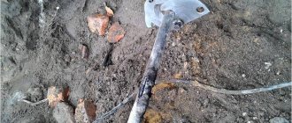
Most cable failures are caused by multiple factors acting simultaneously or sequentially. For cables operating in soil, one of the most serious damage factors is the movement of soil along the cable route, causing one part of the cable to stretch and another to be crushed.
Such movements most often occur in areas of active mining, on artificially created earthen embankments, in mountainous and high-altitude areas, as well as in seismically active areas. High stresses in the soil cause the dielectric in the cable to shear, causing insulation to break and breaking cable sleeves and other cable connections. Dielectric shifts are especially dangerous for oil-paper insulated cables.
What are the main reasons for cable failure?
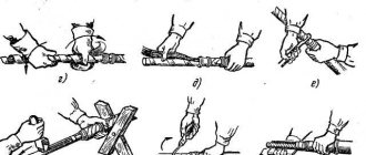
The most common way a cable fails is through damage. If your setup requires you to constantly unplug and plug in devices, don't be surprised if your cables wear out quickly.
- The most common place for cable wear is at the connection between the tube and the plug. Often this tube slips off, leaving the screen and wires inside exposed. Over time, these wires wear out, breaking your connection.
- Another similar way of cable failure is damage due to negligence. Cables left dangling or scattered on the floor are easy to trip over or get caught in. If you apply enough force, you can damage not only the cable, but also the device to which it is connected. That's why it's so important to keep your cables neat and organized.
- The third way to ruin cables is poor manufacturing. Cheap, unlicensed and redundant cables are more likely to wear out, if not break altogether. Make sure you are getting a good cable by purchasing only trusted brands from reputable stores.
- The fourth way cables fail is crimping. Bending, tying, or running a cable around a wall can cause wires to become pinched. Over time, this can cause the wires to transmit less or even no signal.
- The last way a cable can fail is through aging. Over time, exposed metal parts can oxidize, causing connections to become loose. If this happens, it's probably time for you to replace the cable. This is even more true for digital cables as standards and capabilities are updated regularly.
What else affects damage to cable connections?
Other types of cable damage include:
- mechanical,
- electrolytic
- corrosion damage.
These types of damage cause the metal sheaths of oil-paper insulated cables to deteriorate and allow moisture to penetrate, resulting in multiple damages inside the cable as well as damage to the outer insulating coating of any type of cable.
In thermoplastic cables made of PVC or polyethylene, moisture ingress also causes damage to the sealing coating and the formation of water logs. Pitting cable insulation is formed due to erosion of the dielectric as a result of partial discharges. Such failures are characterized by high contact resistance. Voltage testing is used to detect damage early on this model.
When testing a cable, its characteristic impedance and propagation coefficient are determined. The impedance value depends on the cable type and is different for coaxial cable, installation cable, or power cable. Two cables with the same insulating material, manufactured by different manufacturers, can have different values of the same coefficient. Examples of propagation coefficient values for selected dielectric types:
- oil impregnated paper 0.50-0.56n;
- polyethylene 0.64n with foam;
- polyethylene 0.67n;
- Teflon 0.71n;
- 0.94-0.98n air.
Correct determination of the propagation coefficient is important when determining the distance to the fault. The spread coefficient depends on:
- the type of insulation used;
- cable geometry;
- cable service life.
What makes a cable durable?
The best way to get a quality cable is to buy only licensed cables from reputable dealers. Various types of connections have standards that are supported by industry or engineering associations. Some require licenses, royalties or membership fees to produce the cable to the standard.
Most manufacturers indicate on their packaging compliance with current standards. However, if you purchase a counterfeit cable from a reputable dealer, it may not fully meet the standard. Not only can this mean a cable that won't last as long, but it can also damage your equipment.
Manufacturers have also developed several features that can extend the life of the cable. Some manufacturers add an extra sheath on top of their plug that covers the cable tube. This reduces the pulling force on the tube itself if the cable is damaged. This also means that the movement of the cable tube does not necessarily expose the wires underneath.
Additionally, reducing the amount of metal your cable is made from can help prevent corrosion. For example, some manufacturers make HDMI cables that use a carbon fiber shield rather than a metal alloy shield. This can help prevent oxidation if the cable tube is damaged.
Cable damage - measuring system parameters
After determining the cable parameters, the parameters of the measuring system are determined. First, the appropriate measurement range is selected, taking into account that the emitted pulse is attenuated in the cable, and its amplitude decreases as it moves away from the device. The level of damping depends on:
- cable type;
- service life;
- quality of connections.
Logging systems play an important role in the fault detection process. They are used as autonomous systems or systems equipped with automatic protection. Fault recording systems perform their role best because they can record instantaneous values of phase currents and voltages, as well as automatic protection signals associated with the operation of devices installed at both ends of a line or system device.
Thanks to the voltage and current values stored in the device's memory, the type of damage and its time course are determined. Current and voltage values are recorded moments before a fault occurs by means of a time delay device installed on the line. Thus, it is possible to determine the moment of damage and predict its development. The voltage and current values are the basis needed to calculate the distance from the fault location.
Causes of malfunctions of twisted pair cables
“Certification” is the process of comparing the data transmission performance of an installed cabling system to a standard using the performance measurement methodology defined in the standard.
The cable system certification process determines the quality of the cable system components and the quality of the installation work. As a rule, this is required to obtain a warranty from cable system manufacturers. To pass the certification, you must receive a “Passed” result. Technicians need to diagnose the faulty lines and, once the problem is resolved, retest the SCS to ensure that the line characteristics meet performance requirements. The total time required to certify a network not only includes time for measurements, but also documentation and troubleshooting.
Why is advanced diagnostics necessary?
Today's cabling installers must know how to troubleshoot and diagnose high-performance cabling systems.
As newer cabling systems are developed and implemented, every aspect of installation requires a higher level of professionalism and greater attention to detail. New testing options have been added. Connections must be tested using one or two connection models - Permanent Link or Channel - with connections tested and evaluated over a wide range of frequencies and with a large amount of data. Line components must provide higher levels of performance and, accordingly, the quality of installation work must also improve.
With the increasing complexity of these cabling systems, identifying the cause of a failure and quickly restoring the required level of performance has become a challenge. This guide provides best practices for troubleshooting today's cable systems using the Fluke Networks DTX Series CableAnalyzer testers, which will improve productivity and generate greater profitability for your organization.
Troubleshooting Basics
The most common causes of failures in twisted pair cable systems:
- Installation errors - with correct connections, it is necessary to maintain the pairs of wires and the twisting frequency in each pair; It is always necessary to maintain the "original twist" in each pair of wires as much as possible.
- Connectors that do not meet data transmission quality requirements
- Incorrect tester setup
- Defects or damage to the installed cable
- Low quality patch cables*
When discussing network operation, patch cables always receive a lot of attention. Certification is often performed using the Permanent Link Model because the patch cables used in production networks are not yet installed or available.
Before testing the SCS, you must check the following:
- Is the testing standard chosen correctly? – Certification testing is performed as an automated test or “autotest”. The test standard selected for the Autotest determines the connection model (Permanent Line or Channel), the test parameters measured, the test frequency range, and the Pass/Fail criteria for each test.
- Is the connection model chosen correctly?
- Is the correct test adapter being used with a connector whose specifications match those of the connector in the telecommunications outlet (TO) or patch panel?
- Has the reference value been set within the last 30 days? – It is recommended to set the reference value regularly at regular intervals for ease of remembering (for example, every Monday morning)
- Are you using the latest version of the tester software?
- Is the correct NVP set for the cable being tested? – NVP is important when the tester reports length or distance to a fault
- Does the tester operate within the acceptable temperature range and is it calibrated? – Remember that the Fluke Networks CableAnalyzer is a very accurate device that is used to measure noise interference in cables. These products are calibrated at the factory prior to shipment and must be verified every 12 months by an authorized service center. If the tester has been stored in an area that is colder or hotter than the operating environment (for example, left overnight in a vehicle), wait until the tester reaches a stable operating temperature before setting the reference value or making any measurements. This may take 10 to 15 minutes or more depending on the difference in temperatures.
Connection Models
To obtain clear results, it is extremely important to select the correct autotest and connection model. The quality of a Permanent Link is determined in such a way that once high quality patch cables are added to the link, the link performance requirements are automatically satisfied. High quality patch cables are patch cables that are assigned the same grade or category as the lines. This also applies when these cables have a higher level of performance. It is for this reason that it is recommended that new cabling systems be certified using the Permanent Line model and testing standards. When using a permanent line, multiple replacements of patch cables and equipment cables are possible. To use the Permanent Line test model, the cables used to connect the test equipment to the line must be completely transparent to measurements. In effect, this means that field certification testing tools must be more complex because they must subtract values from the test cord effect from each test parameter measured. However, the Permanent Line model includes termination connectors - a mating connection of 8-pin modular plugs (RJ45) on test adapters and line connectors (jacks). Depending on the connector and socket combination used, test results may vary significantly in the areas of key parameters such as Near End Crosstalk (NEXT) and Return Loss. To properly evaluate the quality of the connectors at the ends of the cable (at the TO and at the patch panel) and the termination of the wire pairs in them, the connector at the end of the Permanent Line test adapter that is used in testing will be defined as the reference test connector. This connector is used for testing all frequency dependent parameters with very tight tolerances. Therefore, only a few types of such connectors are used, which differ slightly from each other, and their use ensures highly accurate SCS testing results.
Typically, Channel measurements are performed during maintenance or when testing cables for operating applications. Channel testing after the installation of a new network is completed is not often performed because the patch cables included in each line are rarely available at this time. For proper Channel measurements, the effects of using a mating connection in the tester's Channel testing adapters should be compensated for.
DTX Auto Diagnostic Series
If an AutoTest fails or produces a “minimum acceptable” result, the DTX Series testers automatically process the data to provide cable line diagnostic information. Once diagnostics are complete, the user can press the FAULT INFO key (F1 softkey) to view diagnostic results and test data.
First of all, let's define what is meant by testing with a minimum acceptable result. Test margin is the difference between the measured value and the corresponding Pass/Fail limit value. The margin is positive if the test succeeds, negative if it fails, and zero if the measured value is equal to the limit value. A larger margin indicates that the result is far from the limit. Therefore, a larger positive margin indicates excellent test results. A very small margin means that the test results are close to the acceptable limit. The test result is considered minimally acceptable if the margin value is less than the accuracy of the parameter being tested. For example, the accuracy of the Near End Crosstalk (NEXT) measurement is 1 dB at 250 MHz and the worst case line margin is 0.4 dB at 250 MHz. This NEXT test result at 250 MHz is considered close to the limit and is referred to as the minimum acceptable test result. In this case, the tester automatically performs diagnostics to indicate the possible reason for the minimum acceptable result. This data can be used to identify the problem area, correct the problem and produce a high quality line.
If an error occurs while testing a cable line for correct wiring - a test that verifies that all 8 wires are connected to the correct pins at both ends of the cable - the tester will pause the test and display the results. Figure 3 shows such a connection failure. The circuit in pair 1 is open at a distance of 48 m from the main unit and at a distance of 17 m from the Smart Remote module. It is assumed that the main DTX unit is always located on the left side of the screens. The program execution is paused and the operator is prompted to confirm whether to continue testing. It is often recommended to correct the wiring diagram error before continuing testing.
Broken wires may result in indeterminate test results. For example, the insertion loss of a broken wire cannot be determined. Therefore, all parameters that are calculated using the insertion loss value have an incorrect or undefined value.
The DTX Series' unique diagnostic capabilities are paramount to the tester's functionality in identifying quality problems such as return loss or NEXT. Figure 4 shows the test results screen for a faulty Class E line. Return Loss indicates near-failure situations, while Near End Crosstalk (NEXT), Integrated Near End Crosstalk (PSNEXT), Attenuation to Bidirectional Crosstalk Ratio ( ACR) and Near End Security Aggregate (PSACR) indicate clear failures. The numbers shown in brackets on the right side of the screen indicate the worst-case values of the corresponding testing parameter.
When you press the FAULT INFO key, the tester displays four possible diagnostic options. Figures 5a - 5d show four possible error scenarios. The user must evaluate all of these options, test the cable according to the instructions provided, and if a problem is confirmed, take corrective action. In Figure 5a, the tester indicates the possibility of having more than four connections on a line. The first possibility of a failure occurring after analyzing the test results data. As shown on the tester screen, there are four connections on the line under test. Therefore, diagnostic results are not applicable. Figure 5b in the diagnostic shows that the shorter cable segment, which is 60 feet away from the remote unit, has a Return Loss fault, which causes the minimum acceptable wire pair test results of 4.5. The tester will print the recommended tests: “Check the wiring on the connector and make sure you are using the correct category of connector.” In other words, the reason for the minimum acceptable results for RL on pair 4.5 is the cable trim on the connector or the connector itself. Figure 5c shows the location of the next possible error identified by the diagnostics performed by the tester. At a distance of approximately 17 m from the remote tester unit, excess crosstalk occurs between two combinations of wire pairs. The last possible option is shown on the screen in Figure 5d. The tester identified a connector 9 m from the remote tester unit and an 8 m cord next to the next connector in the line. In this case, the tester identified the cable in the segment between these two connectors as a possible cause of the malfunction. The following message will be displayed: “Make sure you are using the correct type of cable. Category 5 cable is used. This warning indicates that the source of the problem may be an 8-meter cord in a Category 5 cable in a line in which all components must be Category 6 to meet Class E performance requirements. Note that this screen indicates that the second connector at the end of the patch cable is located at a distance of 17 m from the remote tester unit. And which of the automatic diagnostic results is correct?
Figure 6 shows the line configuration created for this test.
Figure 7 shows an image of the actual fault. The wire pairs at the end of the 2 meter patch cable are carelessly unbraided and are causing NEXT failures on that connection, as well as a near critical return loss problem on the 4.5 pair at the same location. In the diagnostics described above, defects were detected at a distance of 18 m from the Smart remote module when testing for return loss and at a distance of 17 m when testing on NEXT. This is what can be called accurate diagnosis.
Once the tester identifies this point on the physical line, this fault becomes obvious. The most practical and often optimal way to resolve a faulty patch cord is to obtain and install a quality Category 6 cable. At this point, the line should be retested to ensure that the faults have been resolved and the line is operational. The actual time it takes to fix this problem should not take more than a few minutes.
Please note the unusual settings for this testing. Using the recommended configuration, the permanent line terminates at the patch panel at one end and at the TO at the other, possibly using a consolidation point (CP) (connection point) at least 15 m from both ends (typically closer to the TO), as shown in Figure 1. In this aspect, the diagnosis depicted in Figure 5a is also correct. This permanent line contains one more connection than in standard situations or than recommended. However, it should be remembered that after replacing the faulty patch cord with a good one, testing of that line, including the abnormal connector, will pass successfully for a permanent Class E line.
If a line fault is detected at the consolidation point, the technician will need to re-terminate the connection after ensuring that the connectors meet Category 6 component requirements.
Automatic connection diagnostics save time and other costs compared to trial and error, which requires re-terminating cables and/or replacing connection equipment in several places to successfully complete testing of a faulty line.
The section describing advanced diagnostic techniques describes how to obtain and interpret basic diagnostic data that is obtained by using the tester's analysis algorithms.
Causes of cable failures
For each of the TIA and ISO mandatory cabling requirements, diagnostic tips are provided that are used to quickly identify the cause of failures when they occur. In some cases, reasons will be given for successful completion of the test, contrary to the existing reasons for completing the test with a “Fail” result.
Wiring diagram
| SCS testing result: | Possible reasons for obtaining this result |
| Break |
|
| Closure |
|
| Aligning a Back Connected Pair |
|
| Cross pair |
|
| Break |
|
Length
| SCS testing result: | Possible reasons for obtaining this result |
| Exceeding Length Limits |
|
| The report shows a length that is less than the actual length |
|
| One or more pairs are significantly shorter |
|
Note: As standard practice, cable length is determined by the length of the shortest pair. The NVP varies between pairs, meaning each pair may report a different length. Compliance with these conditions may result in a three-pair or four-pair cable being tested against the length limit but still receiving a Pass result (for example, a channel length of 101, 99, 103, 102 meters for four pairs). In this case, the correct interpretation would be “Passed.”
Offset/delays
| SCS testing result: | Possible reasons for obtaining this result |
| Exceeding Limits |
|
Insertion Loss (Attenuation)
| SCS testing result: | Possible reasons for obtaining this result |
| Exceeding Limits |
|
NEXT and PSNEXT
| SCS testing result: | Possible reasons for obtaining this result |
| Fail (overall result), *fail (individual component) or *pass (individual component) |
|
| Unintended result "Passed" |
|
Return losses
| SCS testing result: | Possible reasons for obtaining this result |
| Fail (overall result), *fail (individual component) or *pass (individual component) |
|
| Unintended result "Passed" |
|
ACR-F and PSACR-F (previously used names: ELFEXT and PSELFEXT)
| SCS testing result: | Possible reasons for obtaining such a result |
| Fail (overall result), *fail (individual component) or *pass (individual component) |
|
Resistance
| SCS testing result: | Possible reasons for obtaining such a result |
| Fail (overall result), *fail (individual component) or *pass (individual component) |
|
By contacting the specialists of our company, you can avoid many problems. We will help you select high-quality and inexpensive equipment, carry out qualified installation of SCS, installation of video surveillance systems, installation of access control systems and test the SCS for compliance with the category with a verified device.