When operating cable power lines, a big problem is insulation breakdown where it cannot be determined either by visual inspection or by using a low-voltage megohmmeter. A good example is the formation of microcracks in cable insulation, which are filled with moisture. When such cracks do not reach from the outer surface of the cable to the conductor, the megohmmeter cannot determine their presence. At the same time, there is a thin layer of insulation between the moisture-filled crack and the conductive core. When operating voltage is applied, this thin layer of insulation cannot withstand and breakdown occurs.
Therefore, cables are tested at a voltage higher than the rated voltage, which makes it possible to identify hidden defects. The test rules are described in the current PUE-7.
For cables with voltages not exceeding 1 kV, only measuring the insulation resistance with a high-voltage (2.5 kV) megohmmeter is used. However, it should not be less than 0.5 MOhm. The only exceptions are 1 kV cables with plastic insulation - they are tested at increased voltage (see Table No. 1).
For cables with voltages above 1 kV, a test with increased voltage of rectified current is used (the use of the term “rectified current” in PUE-7 is due to the fact that in practice rectifiers without filters are used, that is, they have pulsations at the output) according to Table. No. 1. For cables with paper and plastic insulation up to 35 kV, the test duration is 10 minutes, for cables with rubber insulation for 3 - 10 kV - 5 minutes, for cables with any type of insulation for 110 - 500 kV - 15 minutes.
Table No. 1. Rectified current test voltages for various types of power cables
| Paper-insulated cables for voltage, kV | ||||||||||
| 2 | 3 | 6 | 10 | 20 | 35 | 110 | 150 | 220 | 330 | 500 |
| 12 | 18 | 36 | 60 | 100 | 175 | 285 | 347 | 510 | 670 | 865 |
| Cables with plastic insulation for voltage, kV | Cables with rubber insulation for voltage, kV | |||||||||
| 1 | 3 | 6 | 10 | 110 | 3 | 6 | 10 | |||
| 5 | 15 | 36 | 60 | 285 | 6 | 12 | 20 | |||
If we are talking about a plastic insulated cable that does not have armor and is located in an open space, then it is not required to be tested with rectified voltage.
Cables for 110 - 500 kV with any type of insulation can be tested not only with rectified voltage, but also with alternating voltage with a frequency of 50 Hz. In this case, the effective voltage value should be 1.73 of the rated voltage value specified in the documentation for this cable. The cable insulation resistance must be measured with a special megohmmeter, which gives a potential difference at the measuring terminals equal to 2.5 kV. Measurements are made before and after breakdown tests, from which conclusions are drawn about the state of the insulation. But how to interpret the measurement results if the insulation resistance value for cables with voltages above 1 kV is not standardized in PUE-7? There are two options. The first is to either rely on the characteristics declared by the cable manufacturer. If there are none, then move on to the second option. You need to use a rule of thumb - this resistance should be at least 10 megohms.
For cables with voltages from 6 to 35 kV, the leakage current is standardized. In addition, the asymmetry of leakage currents for several cores in a cable can be normalized (the ratio between the minimum and maximum current leakage). When testing for defects in insulation, it is not so much the absolute value of the leakage current that is important, but the dynamics of its change during the test. If the insulation is good, then the current should be stable, showing a slight downward trend. It is possible that at the very beginning a surge in leakage current may occur, which is actually associated with the charge of the parasitic cable capacitance. If the current increases during testing, this indicates the possible presence of insulation defects. If the current value fluctuates, the test time is increased until the direction of the current change stabilizes and the situation with the insulation condition becomes clear, but not more than 15 minutes. PUE-7 standards for leakage currents and asymmetry coefficient are given in table. No. 2.
Table No. 2. Leakage currents and asymmetry coefficients for power cables
| Cable voltage, kV | Test voltage, kV | Permissible leakage current value, no more, mA | Permissible value of the asymmetry coefficient (Imax/Imin), no more |
| 6 | 36 | 0,2 | 8 |
| 10 | 60 | 0,5 | 8 |
| 20 | 100 | 1,5 | 10 |
| 35 | 175 | 2,5 | 10 |
Pass or fail the test
Testing
A cable test is generally considered to have passed perfectly if:
- the process was carried out without breakdowns, also if the surface discharges were not blocked from the outside;
- the current flowing out during the test does not increase in its indicators;
- the value shown by the resistance on the cable insulation did not change downward.
We often have to deal with the fact that the currents flowing during testing can have a value that is an order of magnitude greater than those indicated in the tables as standard. If this happens, the cable can be used, but its service life will be significantly reduced.
Test conditions
4.1. Testing of cable power lines up to 10 kV is permitted only at positive temperatures. During the cold period (in the cold), frost or ice may appear inside the insulation (in the cable structure). This situation does not allow obtaining reliable parameters, since frozen water particles are a dielectric.
4.2. Before starting tests, check the humidity and presence of condensation on the power cable cores. The presence of water particles can trigger an insulation breakdown, which can lead to failure of not only the electrical installations or other equipment being tested, but also the testing equipment.
4.3. Before testing, thoroughly clean the cable funnels from dust, moisture and other contaminants.
4.4. Atmospheric pressure does not affect the current SCR parameters. In this case, its value must be recorded in the test report.
Determination of the electrical working capacitance of the cores.
Produced for lines 35 kV and above. The measured capacity, reduced to specific values, should not differ from the factory test results by more than 5%.
The capacitance of cable lines is measured using an ammeter-voltmeter method or a bridge circuit.
Ammeter-voltmeter method. allows you to accurately determine capacitances with values of C≥0.1 µF, which corresponds to the parameters of the cables. The measurement scheme for this method is shown in Fig. 2.
Based on the results of measuring voltage and current, the capacitance, μF, is calculated using the formula
where: I - capacitive current, A; U is the voltage on the cable, V; f is the frequency of the network voltage, Hz.
Based on the measurement data, the specific capacitance of the cable is determined, μF/km
In the case when measurement by the ammeter-voltmeter method requires special equipment and instruments, it is desirable to use the bridge method.
When measuring with the bridge method, alternating current bridges such as MD-16, P5026, P595, etc. are used. Measurements are made using an inverted circuit (the instructions for the measurement procedure should be followed). When choosing measuring instruments, it should be taken into account that the specific linear capacitance of cables of 35 kV and above is tenths of μF/km, and the limits for measuring capacitance with AC bridges are in the ranges:
bridge P5026 at a voltage of 3-10 kV - 10 ÷ 1 µF, at a voltage less than 100 V - 6.5 10-4 ÷ 5 10 2 µF;
MD-16 bridge at a voltage of 6-10 kV - 0.3 10-4 ÷0.4 µF, at a voltage of 100 V - 0.3 10-3 ÷100 µF;
bridge P595 at a voltage of 3-10 kV –3 10-5 ÷1 µF, at a voltage less than 100 V – 3 10-4 ÷102 µF.
Burn function
After high-voltage tests have shown the presence of defects, the locations of insulation damage are determined. Devices that detect such damage are able to pinpoint the location if the resistance between the cable cores is less than 1 kOhm. To ensure such resistance, burning is used - changing the voltage and current supplied to the cable cores according to a certain algorithm in order to completely destroy the insulation of the cores in the place where the defect is present. Ideally, after burning, the two wires are connected to each other by a metal “bridge”. In addition to special equipment, the burning function is present in some models of devices for testing cable insulation.
Typical cable damage
High voltage testing allows you to identify the following common types of defects in high-voltage lines:
- breaks (including individual cores) without grounding;
- breaks of one or more wires with their grounding;
- breaks of one or several cores, with grounding of entire cores;
- short circuit between conductors or to ground, occurring as a result of aging of the insulating coating or corrosion of metal shells;
- mechanical damage (most common for cables running in the ground);
- oil leakage from oil-filled cables;
- other types of damage, including multiple violations of insulation integrity or wire breaks along the entire length of the cable.
Among all these defects, single-phase damage is the most common - in this case, one of the current-carrying wires is shorted to the shielding sheath of the cable. In turn, interfacial faults (in which several cores are melted and welded together (and often with a shielding shell) account for no more than 20% of all damage.
If we consider the reasons why such defects occur, we can highlight the following:
- design errors (for example, underestimated cross-sectional area of the cores);
- factory defects (uneven insulation, burrs on current-carrying conductors, etc.);
- mechanical damage during installation;
- violations during installation of couplings;
- cable damage during operation.
In any case, in order to avoid destruction of the cable during operation and to detect its damage in time, tests are carried out using increased voltage.
Testing of cables with cross-linked polyethylene insulation
The features of XLPE cables dictate a different approach to testing. It is known, including according to VNIIKP data, that SPE cables, when operating at alternating voltage, have a significantly higher electrical strength compared to PBI. Therefore, the problems when testing XLPE cables with an alternating voltage of 50 Hz are the same, and even greater, than for PBI cables. However, the use of high direct voltage for testing XLPE cables is not permissible, since under its influence defects arise in the main insulation of the cables, leading to its rapid failure. The solution to this problem turned out to be both simple and original. It turned out that it is possible to use alternating voltage of ultra-low frequency (ELF), of the order of 0.05...0.1 Hz. In practice, this can be interpreted as a constant voltage that changes its polarity slowly, with a period of several seconds. The use of this type of test voltage does not lead to harmful consequences for the XLPE cable. The main thing that this approach provides is the ability to use low-power test facilities for testing. Moreover, in order to ensure testing of long-distance XLPE cables, it is enough to simply reduce the voltage frequency. Modern VLF test installations have this capability.
The permissible test voltage of XLPE cables is significantly less than for PBI. This is explained by the fact that XLPE cables have a significantly lower DC voltage strength compared to PBI cables. The high-voltage VLF installations offered on the market today are significantly more expensive than the testing installations used for PBI cables. In many ways, the cost is related to the power of the installations, which, in turn, determines the possible length of the lines being tested. At the same time, imported models are several times more expensive than domestic ones.
From all of the above it is clear that tests of PBI and XLPE cables differ radically both in the type of test voltage used (DC, AC) and in its level. For PBI cables, the test voltage level is much higher.
How, in this case, to test lines consisting of these two types of cables?
Existing standards
How long does it take to check the insulation strength of power cables? For cables with paper and plastic insulation, it takes 10 minutes after installation, and during operation - only 5 minutes. The same number of minutes is required for a cable whose insulation is made of rubber.
AII-70
To test the strength of electrical insulation, the AII-70 and IVK-5 devices are used, while the latter of them is more often used for field work.
How to correctly carry out high-voltage tests can be illustrated by the example of a power cable of the AAShV brand with a wire cross-section of 3 to 95. Using one of the above-mentioned units, at a current speed of 1-2 kV, in just one second, you can increase the rated voltage to 60 kV. After this, the time for passing the tests begins to count down.
AID-70M
When high-voltage testing of the cable sheath is completed, measurements are usually taken again to determine the resistance of the entire insulation.
Documentation of test results
For each cable line in operation, a passport must be issued, which contains the following information:
- name of the enterprise - owner and its division (department, workshop);
- dispatch name of the cable line and its laying diagram;
- technical data of the line - length, brand and cross-section of the cable, information about connecting and end couplings with an indication of the time of their installation;
- information about tests - when a test or measurement of cable insulation resistance was carried out, an insulation resistance measurement protocol is attached to the passport;
- information about cases of damage and repair work performed.
The results of high-voltage tests are documented in a protocol in the established form. The protocol indicates information about the cable being tested - brand, cross-section, where it comes from and where it is laid. For each phase, the cable insulation resistance measured before and after the test is recorded. The test conditions are also given - the value of the test voltage, the test time and the recorded leakage current in milliamps. A list of instruments used to carry out measurements and the type of testing facility are provided.
At the end, a conclusion is given about the suitability of the line for operation.
Test with increased voltage of rectified current.
Power cables with voltages above 1 kV are tested with increased rectified current voltage.
The magnitudes of the test voltages and the duration of application of the normalized test voltage are given in Table 5.
Table 5. Rectified current test voltages for power cables
| Cable type | Test voltages, kV; for cables for operating voltage, kV | Test duration, min | |||||||
| 2 | 3 | 6 | 10 | 10 | 35 | 110 | 220 | ||
| Paper | 12 | 18 | 36 | 60 | 100 | 175 | 300 | 450 | 10 |
| Rubber brands GTSh, KSHE, KSHVG, KSHVGL, KSHBGD | — | 6 | 12 | — | — | — | — | — | 5 |
| Plastic | — | 15 | — | — | — | — | — | — | 10 |
The test methodology for high-voltage rectified current, as well as installations and equipment for testing, are presented in high-voltage insulation tests of electrical equipment.
During testing, the voltage must gradually rise to the test value and be maintained constant throughout the test period. The test voltage for cable lines with voltages up to 10 kV is raised within 1 minute, and for cable lines with voltages of 20-35 kV - at a speed of no more than 0.5 kV/s.
If the test voltage is monitored using a voltmeter connected on the primary side of the step-up transformer, then some error may be introduced into the measurement results due to the voltage drop in the elements of the test circuit, in particular in kenotrons.
Measurement of leakage currents of a 3-10 kV cable when testing with suspended rectified voltage is carried out using microammeters connected either to the high voltage side of the testing installation or to the zero of the test transformer. When using the latter scheme for measuring leakage currents, the reading may be distorted due to parasitic leakage currents.
When testing power cable lines with increased rectified voltage, their condition is assessed not only by the absolute value of the leakage current, but also by taking into account the nature of the change in the leakage current over time, the asymmetry of the leakage currents by phase, the nature of charge retention and decay, etc. In operation, it is accepted that a cable line can be put into operation if the leakage currents have a stable value, but do not exceed 300 μA for lines with a rated voltage of up to 10 kV. For short cable lines (up to 100 m long) without couplings, permissible leakage currents should not exceed 2-3 µA per 1 kV test voltage. The asymmetry of leakage currents by phase should not exceed 8-10, provided that the absolute values of the currents do not exceed permissible values.
For proper insulation of a power cable, the leakage current decreases depending on the duration of application of the test voltage, and the higher the quality of the insulation, the greater. For a power cable with defective insulation, the leakage current increases over time. If there is a noticeable increase in the leakage current when testing a power cable, the test duration increases to 10-20 minutes. If the leakage continues to increase, if it is not caused by defects in the terminations, the test should be carried out until the cable insulation breaks down.
During testing, the voltage from the rectified installation is applied to one of the cores of the cable under test. The remaining cores of the cable being tested, as well as all cores of other parallel cables of this connection, must be reliably connected to each other and grounded. For three-core cables, the insulation of each core relative to the sheath and other grounded cores is tested. For single-phase cables and cables with separately leaded conductors, the insulation of the conductor relative to the metal sheath is tested.
The cable is considered to have passed the test if no breakdown occurred, there were no sliding discharges or impulses of the leakage current or its increase after it reached a steady value.
After each test of the cable line circuit, it must be discharged according to the given method.
Prices for electrical measuring work "PROFENERGIYA":
| Services | Unit | Cost per unit of measurement, rub. | |
| Electrical installations over 1000 V to 35 kV | |||
| Checking compliance of the installed electrical installation with the requirements of the design documentation | inspection | From 3000 | |
| Checking the presence of a circuit between grounding conductors and grounded elements | dot | From 25 | |
| Testing of fuses, fuse-disconnectors for voltages over 1 kV. | PC. | From 490 | |
| Testing of power cable lines with voltage up to 20 kV. | PC. | From 9500 | |
| Testing of power cable lines with cross-linked polyethylene insulation with voltage up to 35 kV. | Trial | From 8000 | |
| Testing of power transformers, autotransformers, oil reactors and grounding arc arresters with rated voltage up to 35 kV. power up to 63000 kVA | PC. | From 15000 | |
| Testing of switchgear and switchgear. | PC. | From 14900 | |
| Testing of oil, air, vacuum circuit breakers, disconnectors, short circuiters and separators. | PC. | From 1400 | |
| Testing of complete busbars (busbars). | PC. | From 2500 | |
| Testing of busbars and connecting busbars. | PC. | From 2500 | |
| Testing of valve, tubular arresters and surge suppressors. | PC. | From 4000 | |
| Testing of bushings and bushings. | PC. | From 5000 | |
| Testing of suspension and support insulators | PC. | From 6000 | |
| Testing of dry current-limiting reactors. trial | Trial | From 5000 | |
| Inspection of cells (checking and adjusting relay equipment) | Complex | From 15000 | |
| Testing of AC electric motors with rated voltage up to 20 kV. | Complex | From 20000 | |
| Checking switchgear and their connections | Complex | From 10000 | |
| Testing of electrical equipment with increased voltage 1 kV industrial frequency | Measurement | From 500 | |
| Testing of synchronous generators and compensators | Measurement | From 8000 | |
| Testing of measuring current transformers | Trial | From 5000 | |
| Testing of voltage transformers | Trial | From 3500 | |
| Testing of dry current-limiting reactors. | Trial | From 4500 | |
| Capacitor testing. | PC. | From 1800 | |
| Transformer oil testing | Sample (1 liter) | From 8000 | |
| Testing power lines with voltages above 1 kV | Complex | From 20000 | |
| Comprehensive testing | |||
| Carrying out electrical measuring work with the preparation of a technical report from 1000V to 35kV | |||
| Acceptance tests. | Complex of works | From 20000 | |
| Performance tests. | Complex of works | From 20000 | |
| For certification purposes | Complex of works | From 8000 | |
| Engineer visit | Departure | For free | |
| Drawing up single-line diagrams | PC. | From 2000 | |
| Drawing up a grounding device passport | PC. | From 10000 | |
Locations of insulation defects are also determined in stage 2. First, preliminary localization is carried out using the loop method and precision bridge, and then precise identification of defective locations is carried out using the step voltage technique.
To identify locations of damage to the cores themselves, various technologies are used:
- for a 3-core cable – burning;
- for initial localization - non-burning methods;
- for high-precision detection of defects - acoustic method.
Timely testing of high-voltage lines is necessary to increase the reliability of electrical networks and increase the period of their uninterrupted use.
| Carrying out electrical measuring work with the preparation of a technical report from 1000V to 35kV | |||
| Acceptance tests. | Complex of works | From 20000 | |
| Performance tests. | Complex of works | From 20000 | |
| For certification purposes | Complex of works | From 8000 | |
| Engineer visit | Departure | For free | |
| Drawing up single-line diagrams | PC. | From 2000 | |
| Drawing up a grounding device passport | PC. | From 10000 | |
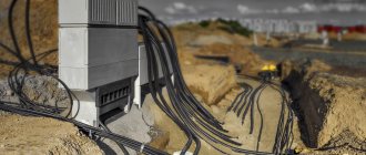
Modern electrical capabilities make it possible to provide energy to any national economic facility. Due to the density of urban infrastructure, as well as the minimum distance between industrial and manufacturing enterprises, power lines are equipped with high voltage power cables. When distributed to consumption points, it is transformed to the required level.
Beginning of work
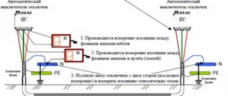
We connect the conductors to each other and to the ground
The test is carried out after applying a higher voltage, but the current must be rectified. It must be applied to all parts of the power cable individually. In this case, everything to which voltage is not applied must be grounded, namely:
- unused cores;
- metal protection;
- shielding surface.
So it is possible to determine whether the insulation between a certain residential area and the surface of the earth is strong, and of course, also in relation to other phases.
Two conductors and a screen are grounded
If the cable is not armored and not shielded, then the voltage is applied between the desired core and other parts that are connected to each other and grounding.
You can simultaneously take all the phases in the cable, no matter how many there are, and test everything at once with an increased voltage, but then the value of the leakage currents must be accurately measured for each wire. If the power cable has only one phase conductor, protected by armor or a shielding surface (made of cross-linked polyethylene), then this voltage must be applied between one of the conductors and the shell, in the latter case this will be metal protection or a shielded coating.
Two conductors and armor are grounded
The power cable is completely de-energized from the equipment connected to it or the buses connected to it; its wires are separated and diverted to the sides by 15 cm.
Frequency of testing during operation.
Cables with voltage 2-35kV:
a) once a year - for cable lines during the first 2 years after commissioning, and thereafter:
- Once every 2 years - for cable lines for which during the first 2 years there were no emergency breakdowns or breakdowns during preventive tests, 1 time per year for cable lines on the routes of which construction and repair work was carried out and on which emergency breakdowns systematically occur isolation;
- 1 time every 3 years - for cable lines in closed areas (substations, factories, etc.); during major repairs of equipment for cable lines connected to units, 6-10 kV cable jumpers between busbars and transformers in TP and RP ;
b) It is permissible not to carry out the test:
- For cable lines up to 100 meters long, which are outputs from switchgear and transformer substations to overhead lines and consisting of two parallel cables;
- For cable lines with a service life of more than 15 years, on which the specific number of failures due to electrical breakdown is 30 or more failures per 100 kilometers per year;
- For cable lines subject to reconstruction or decommissioning in the next 5 years;
c) It is allowed by order of the technical manager of the enterprise to establish
other values of test frequency and test voltages:
- For supply cable lines for voltage 6-10 kV with a service life of more than 15 years with a number of connecting couplings of more than 10 per 1 kilometer of length;
- For supply cable lines with a voltage of 6-10 kV with a service life of more than 15 years, on which only KVV and KVB types of terminations and locally manufactured couplings are installed, with a test voltage value of at least 4 Un and a frequency of at least 1 time in 5 years.
- For cable lines with a voltage of 20-35 kV, during the first 15 years the test voltage should be 5 Un, and then 4 Un.
6.3.8 Cables for voltage 3-10 kV with rubber insulation:
- in stationary installations – once a year;
- in seasonal settings - before the onset of the season;
- after a major overhaul of the unit to which the cable is connected.
Why are tests carried out?
During long-term operation, cable lines are inevitably exposed to external influences.
The factors that determine the wear of the CL include:
- sharp amplitude of seasonal temperatures;
- groundwater activity;
- excessive atmospheric activity (ice storm is especially dangerous);
- soil mobility.
In addition, constant overloading of lines has a detrimental effect. As the insulating layer wears out, the CL gradually loses its original performance characteristics.
To prevent external factors from having a destructive effect, it is recommended to systematically test cable lines with high voltage. Proper organization of testing ensures the flawless functioning of networks, as well as minimizing emergency and abnormal situations.
Types of tests
The first thing to establish is the resistance of the cable insulating sheath. In this case, measurements are carried out using a megger when a current voltage of 2,500 V is supplied. In this case, the resistance should be: for lines up to 1,000 V - at least 500 kOhm, and for lines over 1,000 V - at least 10 MOhm.
High voltage cable testing
The next test is to check by applying too much voltage. In this case, the accompanying leakage currents are measured, their nature and phase asymmetry are determined. The use of this method allows you to check the integrity and homogeneity of the cable much more accurately than with a megger (and for some types of defects such a check is the only possible one).
Before starting, ground the cable sheath, as well as all its cores, except the one being tested. Depending on the operating voltage of the line and the material of its insulation, the magnitude of the increased voltage, as well as the time it is applied to determine the breakdown, is different (you can use the table to correctly select the applied voltage and time).
It should also be remembered that if the cable being tested is located in parallel with another, then its phasing should be performed. To do this, operating voltage is applied to one end of the cable, and it is measured at the other.
The next type of check is monitoring oil-filled lines. During this process, a series of liquid measurements are carried out: for compliance with operating characteristics and for the absence of insoluble gases (the amount of the latter should not be more than 0.1%), and for lines above 110 kV - also soluble ones.
Checking the cable insulation
Checking the high-voltage line for integrity can also be done using an ohmmeter. To do this, one of the cores is determined (obviously intact) and further measurements are taken relative to it (at the same time, the resistance of the circuits of the remaining closed wires is determined).
Also, the current distribution in the conductors is measured. In this case, the amount of unevenness with a working cable should exceed 10%.
Cable testing method
On cable lines with an operating voltage of 20 kV or more, the electrical capacitance value is determined. This is done either by using a bridge circuit or using a voltammeter.
Ammeter-voltmeter method
High-voltage cables in plastic insulation are tested by applying an increased rectified voltage for 1 minute.
Cable sheaths in metal armor are checked for the presence of corrosion.
Also, periodic inspection of couplings, seals, cable manhole structures and other technical elements is carried out.
Test methods
7.1. Monitoring the integrity, identity and phase rotation of SCL cores:
7.1.1. Checking the integrity, identity and alternation of power line cores is carried out after completion of installation work or reinstallation of couplings. If the test is performed during operation, first disconnect the power cable cores from the TP or RU busbars.
7.1.2. Check the integrity of the cores using a megohmmeter.
7.1.3. After connecting the SCL to the network, test the correct phase rotation. The essence of phasing is to check the correspondence of the phases on the busbars of the switchgear with the same conductors at the other end of the power cable connected to them.
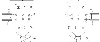
7.1.4. Perform phasing of 6 or 10 kV SCL using a voltage indicator equipped with an additional resistance (Fig. 1):
Fig.1. Phasing of SCL 6 or 10 kV under voltage.
a) the phases of the busbars and cables correspond; b) the phases of the busbars and cables at the connection point of the SCL do not correspond; 1 - voltage indicator; 2 — resistance tube; 3 - cores; 4 — tires; 5 — ending; 6 — SCL; 7 — tire release connector.
7.2. Insulation testing
7.2.1. Check the insulation of the power cable by measuring the resistance with the SCL completely turned off.
7.2.2. Before checking, make sure that the funnels and armor are securely grounded. Then connect them with “crocodiles” (special clamps) to the mobile ground. Leave the other end of the power cable free.
7.2.3. Move the ends of the wires apart no closer than 150–200 mm from each other.
7.2.4. When it is not possible to separate the ends of the cores from each other by more than 150 mm or if they are located close to grounded elements of the equipment, insulate the ends of the cores with protective covers or caps.
7.2.5. Make sure there is no voltage on the object. Remove dust and other contaminants from the cable insulation.
7.2.6. Connect the megohmmeter contacts to the power cable or electrical installation being tested using separate wires with an insulation resistance of at least 100 MOhm.
7.2.7. Take measurements with the instrument needle in a stable position. Rotate the generator handle evenly at 120 rpm for 1 minute. Record the resistance parameters according to the arrow indications.
7.2.8. Measure the insulation resistance of all cores one by one, having previously connected the free ends with a portable resistance, guided by the following diagram (Fig. 2):
Fig.2. Scheme for measuring parameters of insulation resistance of SCL.
7.2.9. In the same order, measure the insulation resistance of SCL and control cables. In this case, take measurements between all pairs of cores:
- phase - phase;
- phase - zero;
- phase - protective conductor;
- zero - protective conductor.
When measuring, it is allowed to combine the working zero with the zero of the protective conductor. Measure the insulation resistance of a four-core power cable relative to the grounded elements of the electrical installation.
7.2.10. Before each measurement, be sure to discharge the power line by connecting metal parts to ground for at least 2 minutes. The insulation resistance value of a cable up to 1 kV must be more than 0.5 MOhm. For lines from 1 kV, insulation resistance parameters are not regulated. Take measurements both before and after testing the SCL with increased voltage.
7.3. SCL testing with increased direct current voltage (PNPT)
7.3.1. Testing of PNPT power lines is required to detect local cracks, erosion, gas inclusions, and other concentrated defects that cannot be identified during measurements with a megohmmeter.
7.3.2. To locate structural damage, test the damage with high voltage. To do this, use the special installation “AID-70” or its equivalent.
7.3.3. Carry out the tests in a manner similar to measuring insulation resistance using a megohmmeter. Apply voltage alternately to all phases, having previously grounded the other conductors and the insulating screen of the cable according to the following diagram (Fig. 3):
Fig.3. Testing SCL PNPT.
7.3.4. It is allowed not to test the shells of single-core air routes without armor or metal screens.
7.3.5. The insulating shells of single-core SCLs with metal screens or armor are tested between the cores and screens.
7.3.6. Test shells of multi-core power lines without armor or screens between each core and the remaining conductors connected to each other and grounding.
7.3.7. Test the shells of multi-core SCLs with a common screen (armor) between all the cores and other conductors combined with each other and the armor (shell, screen).
7.3.8. Perform the above tests only after preliminary grounding of the armor, shell or shield.
7.3.9. Test plastic insulation of power lines laid in the ground between shells (screens) disconnected from grounding and the ground.
7.3.10. Test voltage parameters are indicated in table No. 2:
| type of power cable, kV | less than 1* | 6 | 10 | ||
| paper insulating sheath | |||||
| P | 6 | 36 | 60 | ||
| TO | 2,5 | ||||
| M | — | ||||
| plastic insulating shell | |||||
| P | 3,5 | 36 | 60 | ||
| TO | — | ||||
| M | — | ||||
| rubber insulating shell | |||||
| P | 6 | 12 | 20 | ||
| TO | |||||
| M | 6* | 12* | 20* | ||
T. No. 2. Test voltage for SCL, kV
* - it is allowed not to test overhead single-core power lines with a plastic sheath without screens (armor); ** - after repair work without reinstalling the SCL, the shell is tested with a voltage of 2.5 kV using a megohmmeter. In this case, it is permitted not to carry out the test with increased DC voltage.
7.3.11. During acceptance testing of a power line up to 10 kV with paper or plastic shells, the duration of exposure to high test voltage is 10 minutes. When testing an operating power cable - 5 minutes. SCL 6–10 kV with rubber sheaths are tested for 5 minutes.
7.3.12. Permissible leakage currents (LLC) taking into account the parameters of the test voltage and permissible asymmetry coefficients (ACA) are indicated in Table No. 3.
| SCL, kV | voltage, kV | DTU, mA | DKA |
| 6 | 36 | 0,2 | 8 |
| 10 | 45 | 0,3 | |
| 50 | 0,5 | ||
| 60 |
T. No. 3. Permissible leakage currents and asymmetry coefficients for SCL.
7.3.13. Frequency of SCL testing during operation:
- cable routes 2–35 kV: once every 12 months during the first 24 months after putting the power route into operation;
- Once every 24 months after 2 years of operation of the power line, if there were no emergency breakdowns on the route, including during preventive (scheduled) electrical tests;
- 1 time in 12 months, when construction or installation and repair activities were carried out on the line, or emergency breakdowns of shells regularly occur on the route;
- 1 time every 36 months for power lines laid in a closed area (substation, plant, etc.);
- 1 time every 36 months during the overhaul of electrical equipment of cable routes connected to electrical installations;
- 1 time every 36 months during the overhaul of 6–10 kV jumpers mounted between transformers and RP or TP buses;
- power lines up to 100 m based on 2 parallel cables, providing outputs to overhead routes from a transformer substation or switchgear;
- 6–10 kV supply lines with more than 10 couplings on a 1 km section during an operation period of more than 15 years;
- Once every 12 months - power lines connected to stationary electrical installations;
7.4. Test order:
- Connect a mobile laboratory of the ETL-10-5M series or other similar equipment to a diesel generator or to a fixed 220/380V network.
- Set the switch on the control panel to the "High Voltage DC Test" position.
- Slowly increasing the voltage supply with a rheostat, bring it to the value specified in T. No. 2, taking into account the type of test and the type of power line.
- The duration of the connection (exposure to the cable with high voltage) is specified in clause 7.2.10.
- Reduce the test voltage to zero by smoothly rotating the rheostat knob counterclockwise.
- Make sure that there is no residual voltage on the tested line, then disconnect the installation from the cable (electrical installation) being tested.
During the testing process, strictly follow the requirements of POT RM, as well as the standards specified in section No. 9. “Safety instructions and environmental requirements” of this manual.
7.4.1. The test results are considered satisfactory if during the testing there were no:
- breakdowns or overlapping of insulation;
- sudden changes in ammeter readings (current surges) or voltmeter (voltage dips);
- appearance of smoke, odors or burning;
- listening to discharges.
7.4.2. After completing the organic insulation tests, feel the surface of the sheath to ensure that there are no localized heating conditions.
7.5. Testing SCL with high voltage AC 50 Hz
Perform tests in a sequence similar to the procedure for testing the power line with direct current voltage, set out in paragraph 6.3.13.
7.6. Measuring current distributions in single-core SCLs
7.6.1. On power lines, the parameters of currents flowing not only in the conductors, but also in the armor and metal shells are measured. Take measurements using a current clamp.
7.6.2. Taking into account the type of armor material, insulation and position of the power route in space, the magnitude of the flowing currents can reach 100% of the core currents, which affects the heating of the line. Simultaneously with measuring currents at a load close to the rated value, measure the temperature of the outer sheaths of the cables to calculate the amount of heating of the cores. Take temperature measurements on the hottest sections of the lines. Their value should not exceed the permissible values for specific sections of the cable line.
7.6.3. If uneven current distribution is detected above 10%, equalize the currents across phases. This is necessary to prevent individual cables from limiting the total capacity of the entire line
Test with increased voltage of rectified current.
Testing the insulation of cable lines with increased voltage of rectified current is carried out in order to identify local concentrated defects that are not detected when measured with a megohmmeter, by bringing them to breakdown during the test. Such a test with increased voltage of rectified current is carried out from a special installation such as: AID-70, SKAT-70, etc.
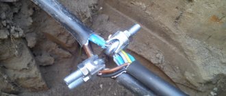
The voltage from the installation is applied in turn to each phase of the cable, while grounding the other two phases and the cable sheath (similar to measuring insulation with a megohmmeter). The circuit for testing the cable with increased voltage of rectified current is shown in Figure No. 3.
Rice. No. 3 Testing the cable with increased rectified voltage.
Insulation of single-core cables without metal screen (sheath, armor),
laid in air are not tested. The insulation of single-core cables with a metal screen (sheath, armor) is tested between the core and the screen. The insulation of multi-core cables without a metal screen (sheath, armor) is tested between each core and the remaining cores connected to each other and the ground.
The insulation of multi-core cables with a common metal screen (sheath, armor) is tested between each core and the remaining cores connected to each other and the screen (sheath, armor). For all of the above types of tests, metal screens (shells, armor) must be grounded. Plastic sheaths (hoses) of cables laid in the ground are tested between screens (sheaths) disconnected from the ground and the ground. Plastic sheaths (hoses) of cables laid in air are not tested. The test voltage value is taken in accordance with table No. 2
Test voltage kV, for power cables.
Table No. 2
| Type of test | Test voltage (kV) for cable lines | ||
| Paper insulated cables | |||
| Up to 1kV | 6kV | 10kV | |
| P | 6 | 36 | 60 |
| TO | 2,5 | 36 | 60 |
| M | — | 36 | 60 |
| Type of test | Plastic insulated cables | ||
| Up to 1kV* | 6kV | 10kV | |
| P | 3,5 | 36 | 60 |
| TO | — | 36 | 60 |
| M | — | 36 | 60 |
| Type of test | Rubber insulated cables | ||
| Up to 3kV | 6kV | 10kV | |
| P | 6 | 12 | 20 |
| TO | 6 | 12 | 20 |
| M | 6** | 12** | 20** |
* - high voltage testing of single-core cables with plastic insulation without armor (screens) laid in the air is not carried out.
** - after repairs not related to cable reinstallation, the insulation is checked with a megohmmeter for a voltage of 2500V, and testing with increased rectified voltage is not performed.
For cables for voltages up to 10 kV with paper and plastic insulation, the duration of application of the full test voltage during acceptance tests is 10 minutes, in operation 5 minutes. For cables with rubber insulation for voltage 6-10 kV, the duration of application of the full test voltage is 5 minutes.
Permissible leakage currents depending on the test voltage and permissible values of the asymmetry coefficient when measuring leakage current are given in Table No. 3. The absolute value of the leakage current is not a rejection indicator. Cable lines with satisfactory insulation must have stable leakage current values. During testing, the leakage current should decrease. If there is no decrease in the leakage current, or if it increases or becomes unstable, the test is carried out until the defect is identified, but not more than 15 minutes.
Tests: how they are carried out
The first check for serviceability is carried out immediately after laying the cable, even before the official commissioning. Later in everyday functionality this operation is repeated.
Work is not carried out at sub-zero temperatures. Even a slight drop in the mercury column beyond zero is a good reason to cancel tests. The fact is that icy water particles have dielectric properties (some of them are very likely to get into the cable). High voltage tests will be useless or the results obtained will not be reliable.
The test method with increased rectified voltage is that it is applied to each cable core (while the rest are grounded).
Leakage is defined as follows:
- insulation test to earth;
- phase-to-phase insulation testing.
The performance of the CL is recognized if shocks and small discharges are not traced. When completed, the line is discharged.
High-voltage testing of cross-linked polyethylene cable (regulations)
| Periodicity |
Important ! If there are no breakdowns, the cable sheath is inspected for integrity once every 5 years. | |
| First method | Second method | |
| Testing 10 kV XLPE cable | It is carried out using alternating voltage with a frequency of 0.1 Hz. Duration: 30 minutes. If the cable line repair work has just finished, 20 minutes is enough. Important ! An industrial diagnostic VLF installation for XLPE cables is used. Test procedure:
| Checking CL 10 6 kV is performed with alternating voltage (10 or 6 kV, respectively). Voltage is applied between the core and the screen. Duration - 24 hours. Test procedure:
Important ! Timing begins from the moment the voltage rises to the maximum level. |
| Current leaks considered normal | For a 6 kV cable - up to 200 µA. For 10 kV - no more than 500 µA. | |
A licensed engineer conducts 10 kV cable testing with quality assurance. Availability of licenses from Rostekhnadzor and SRO, modern equipment - a guarantee of the accuracy of the results obtained. Based on the test results, our specialists prepare a report.
Checking the integrity and phasing of cable cores.
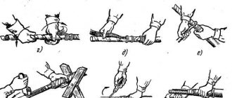
Before putting the cable into operation, its phasing is carried out, i.e. ensures that the cable phases correspond to the phases of the connected section of the electrical installation. The test is carried out by dialing using telephone handsets or a megohmmeter. Based on the inspection, the cores are colored in accordance with the coloring adopted at this installation.
The technology of “dialing” using telephone handsets is as follows: one worker connects his telephone handset to the cable core and sheath (the grounded part of the electrical wiring), and the other alternately to the cable cores on his side until he reaches the core to which the first one connected worker. In this case, a telephone connection is established between the workers and they can agree on the procedure for checking another core. Temporary tags with appropriate markings are hung on the inspected cores. Testing the cores by “continuity” will be successful if the possibility of bypass circuits is excluded. To avoid errors, you must make sure that communication is possible only over one core; To do this, connect the tube to each of the remaining wires and make sure that there is no connection through them. For dialing, low-impedance telephone handsets are used, and a flashlight battery is used as a power source.
After preliminary testing, before putting the cable line into operation, it is phased under voltage. To do this, operating voltage is supplied from one end of the cable, and from the other end the phase correspondence is checked by measuring voltages between like and unlike phases. Carbonation is produced using voltmeters (in networks up to 1 kV) or voltmeters with voltage transformers, as well as using voltage indicators such as UVN-80, UVNF, etc. (in networks with voltages above 1 kV),
The order of phasing in lines of different voltages is approximately the same. Thus, phasing of a cable line using voltage indicators is performed in the following sequence (see Fig. 1). The serviceability of the voltage indicator is checked, for which the probe of the tube without a neon lamp touches the ground, and the probe of the other tube is brought to the core of the energized cable, and the neon lamp should light up. Then the probes of both tubes touch one live wire. The indicator lamp should not light up. After this, the presence of voltage is checked at the terminals of the electrical installation and cable (see Fig. 1c). This check is carried out in order to exclude an error in the phasing of a line that has an open circuit (for example, due to a faulty fuse). The process of phasing itself consists of touching the probe of one indicator tube to any extreme terminal of the installation, for example, phase C, and the probe of the other tube to alternately touch three terminals from the side of the line being phased (see Fig. 1d). In two cases of contact (C-A 1 and C-B1) the neon lamp lights up, in the third (C-C1) the paw will not light up, which will indicate the same phases. Other phases of the same name are defined similarly.
Test methods.
1. Checking the integrity and phasing of the cable cores.
Determination of the integrity of the cores and phasing of cable lines is carried out after completion of installation, reinstallation of couplings or disconnection of cable cores during operation.
Determination of the integrity of cable cores with voltages up to 10 kV is carried out using a megaohmmeter. After switching on the CL, the correct phasing is checked.
The essence of energized phasing is to determine the correspondence of the cable phase, which is energized from the switchgear at the opposite end of the cable, to the supposed phase of the same name of the switchgear buses where phasing is performed. For phasing 6 and 10 kV cable lines under voltage, 10 kV voltage indicators are used, complete with additional resistance, Figure No. 1. The integrity and coincidence of the phase designations of the connected cable cores must correspond.
Rice. No. 1 Phasing of live cable lines.
a – correspondence of cable and bus phases; b – different phases of buses and cables at the connection point of the latter; 1 – voltage indicator; 2 – resistance tube; 3 – wire; 4 – tire; 5 – end seal; 6 – cable; 7 – tire deflation connector.
Measuring current distribution in single-core cables
On the power cable, currents flowing both in the conductors and in the metal sheaths and armor are measured. Measurements are made using current clamps.
Depending on the sheath material, armor and position of the cable in space, the currents in them can reach 100% relative to the core current and greatly affect the heating of the cables. Simultaneously with measuring currents at loads close to the rated load, the temperature of the outer covers of the cables must be measured, from which the temperature of the core can be calculated. This temperature should be measured at the hottest point of the cable line and should not exceed the permissible temperature for a given measurement location. If the current distribution is uneven by more than 10%, when individual cables limit the throughput of the entire group of cables, measures must be taken to equalize the currents across phases.
Test report for power cable line above 1000V
Below is an example of filling out the test report tables:
In the “General Data” table, in the column number of couplings, I suggest recording not only intermediate couplings, but also end couplings. In this case, even on a cable without intermediate couplings, it is necessary to indicate the number 2 in this column. With this filling, this column remains empty only in the case of testing the power cable, for example on a drum, or before laying and installation.
| Beginning of CL | End of CL | Cable type | Length, m | Number of couplings | Note |
| ZRU, cell 1 | TP-2, T-1 | SBG 3x35 | 250 | 2 | — |
In the table “High Voltage Insulation Test”, in the leakage current column, it is necessary to record the current at the beginning of the test (steady-state) and the current at the end of the test before removing the voltage.
| Name | Cable | Note | ||
| L1–(L2+L3+^) | L2–(L1+L3+^) | L3–(L2+L1+^) | ||
| Usp (kV) | 60 | 60 | 60 | |
| Iut. (µA) | 110/100 | 120/100 | 110/80 | start/end |
| Cont. tests | 5 minutes | 5 minutes | 5 minutes |
What should specialists be guided by when conducting tests: GOST or STO?
From the table above it is clear that the STO clearly establishes the use of rules for operational testing of cable line insulation, defined for XLPE cables, both for combined cable lines and for PBI lines. It should be noted that the VLF test modes in service stations differ significantly from those proposed by GOST 55025-2012 for XLPE cables. If this is justified, then the question arises about the need to adjust GOST.
At PJSC ROSSETI, the problem of a unified regulatory approach to testing PBI and XLPE cables has been resolved. The question of the “undertesting” of PBI cables is left out of the question. One can discuss the applicability of testing regimes for XLPE cables for PBI cables, but the main thing is that certainty and legality have appeared. Specialists of PJSC ROSSETI can now work not at their own risk, but based on a specific regulatory document, but then the question arises:
- What should many other large and small enterprises operating combined power cable lines be guided by?
- Refer to the fact that GOST is a recommendation document and continue to be guided by your own experience and common sense?
- Or has it come time to adjust GOST standards to meet the requirements of the time?
There are currently no clear official answers to these questions.