What is resistance
Current flowing through wires and various radio components wastes its energy. This phenomenon is quantitatively expressed by the magnitude of the resistance. In electrical engineering, it is divided into active and reactive resistance. In the first case, when a current passes, part of its energy is converted into a thermal form, and sometimes into others (for example, it manifests itself in chemical reactions). The value of active resistance depends on the frequency of alternating electric current and increases with its increase.
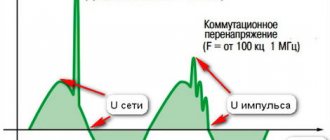
The second type of resistance has a more complex nature and occurs when a consumer of electricity is turned on or off in an AC or DC network. In a circuit with reactance, the energy of the electric current is partially converted into another form, and then transferred back, that is, a periodic oscillatory process is observed. Circuit impedance includes active and reactive types, which are taken into account according to special rules.
Differences between active and reactance
The difference between active and reactance is that when electric current passes through circuit components carrying a resistive load, power losses occur in the form of heat, which cannot be converted back into electrical energy. An illustrative example is an electric stove burner that releases thermal energy. Lighting devices, electric motors, and various cables also have these properties. The phases of the voltage and electric current passing through such components will coincide.
It will be interesting➡ Circuit breakers
What does the resistance of a conductor depend on?
Reactive loads are distinguished by the presence of capacitive properties or the ability to induct. In the first case, the value of the resistance under consideration depends on the capacitance, in the second - on the electromotive force of self-induction.
Important! A quantity, in contrast to an active one, can have plus and minus signs. It depends on which direction the phase shift is going. When the electric current is ahead of the voltage, there will be a negative indicator, otherwise it will be positive.
Which resistance is called reactive and which is active?
Active electrical resistance is an important parameter of the electrical network, which determines the conversion of electrical energy entering a section of an electrical circuit or a separate electrical element into any other type of energy: chemical, mechanical, thermal, electromagnetic. I consider the transformation process irreversible.
Types of the quantity under consideration and formulas for its calculation
Reactance is otherwise called reactance and is the resistance of electrical circuit elements, which is caused by measuring the strength of electric current or voltage due to the existing capacitance or inductance of this element. During reactance, an exchange process occurs between an individual network component and an energy source. This concept is often referred to as simple electrical resistance, but it differs in some respects.
The flow of alternating current does not depend on the type of resistance of the elements and the entire network
Active and reactive resistance
When the electrical energy of a circuit component is irreversibly changed into other types of energy, the resistance of the element is active. When carrying out the exchange process of electrical energy between a circuit component and a source, the resistance is reactive.
In an electric stove, electricity is irreversibly converted into heat, as a result of which the electric stove has active resistance, as well as elements that convert electricity into light, mechanical movement, etc.
In an inductive winding, alternating current produces a magnetic field. Under the influence of alternating current, a self-inductive emf is formed in the winding, which is directed towards the current when it increases, and along the direction of the current when it decreases. Therefore, the emf has the opposite effect of a change in current, creating inductive reactance in the coil.
With the help of self-induction EMF, the energy of the magnetic field of the winding is returned to the electrical circuit. As a result, the inductance winding and the power source exchange energy. This can be compared to a pendulum, which, when oscillating, converts potential and kinetic energy. It follows that the resistance of the inductive coil has reactance.
Self-induction does not form in a DC circuit, and there is no inductive reactance. In the circuit of the capacitor and the alternating current source, the charge changes, which means that alternating current flows between the capacitor and the current source. When the capacitor is fully charged, its energy is greatest.
In a circuit, the voltage of a capacitor creates opposition to the flow of current with its resistance, and is called reactive. Energy is exchanged between the capacitor and the source.
It will be interesting➡ Circuit breaker - what it protects from and how it works
After the container is fully charged with direct current, its field voltage equalizes the source voltage, so the current is zero.
The capacitor and coil in an AC circuit operate for some time as a consumer of energy while they accumulate charge. And they also work as a generator when returning energy back to the circuit.
To put it in simple words, active and reactance is the opposition to the voltage reduction current on a circuit element. The magnitude of the voltage reduction on the active resistance is always in the opposite direction, and on the reactive component it is in the same direction as the current or in the opposite direction, creating resistance to the change in current.
Real circuit elements in practice have all three types of resistance at once. But sometimes some of them can be neglected due to their insignificant values. For example, a capacitance has only capacitive reactance (neglecting energy losses), lighting lamps have only active (ohmic) resistance, and the windings of a transformer and electric motor have inductive and active resistance.
Active resistance
In the circuit of action of voltage and current, it creates counteraction, reducing the voltage on the active resistance. The voltage drop created by and opposing the current is proportional to the active resistance.
When current flows through components with active resistance, the reduction in power becomes irreversible. You can consider a resistor that generates heat. The released heat is not converted back into electricity. Active resistance may also have a power transmission line, connecting cables, conductors, transformer coils, electric motor windings, etc.
A distinctive feature of circuit elements that have only an active resistance component is the coincidence of voltage and current in phase. This resistance is calculated by the formula:
R = U/I, where R is the resistance of the element, U is the voltage across it, I is the current flowing through the circuit element.
Active resistance is affected by the properties and parameters of the conductor: temperature, cross-section, material, length.
What are the differences?
The difference between these types of electrical resistance is that energy does not accumulate “inside” the activity type, since it enters the active element and is given to the environment in the form of another type. This could be heat or mechanical lifting of a load, a glow, a chemical reaction, or giving something speed.
Inductive quantity and its formulas
Important! The energy supplied to an electrical element with active electrical resistance is transformed and converted, but is not returned to the network.
Reactive resistance, on the contrary, accumulates energy within itself for ¼ of the entire period of the sinusoidal electric current, and over the next quarter returns it back to the network. That is, the energy received is not transferred to the environment.
Complex resistance of an individual electrical element of the network R
In the activity type, the phases of electric currents and voltages coincide, therefore, a certain amount of electricity is released. In reactive form, the phases of electric current and voltage diverge, so energy is transferred back. This largely explains why active electrical elements heat up, while reactive elements do not.
Active resistance in an alternating sinusoidal current circuit
Areas of manifestation
The reactance of electrical resistance manifests itself in capacitance and induction. The first is determined by the presence of capacitance in the conductors and windings or the inclusion of various capacitors in the AC electrical circuit. The higher the capacitance of the consumer and the angular frequency of the electric current signal, the lower the capacitive characteristic.
You may be interested in this Features of active-capacitive load
The resistance that a conductor provides to alternating current and the electromotive force of self-induction is called inductive. It depends on the inductance of the consumer. The higher its inductance and the higher the frequency of alternating electric current, the higher the inductive electrical resistance. It is expressed by the formula: xl = ωL, where xl is the electrical induction resistance, L is the inductance, and ω is the angular frequency of the current.
Capacitive reactance electrical resistance manifests itself, for example, in a capacitor, which accumulates electricity in the form of an electromagnetic field between its plates. Inductive electrical reactance can be observed in an inductor, which stores energy in the form of a magnetic field inside its winding.
Any resistor, power lines, windings of a transformer or electric motor can have active electrical resistance.
EMF induction can be observed in the throttle
Thus, active resist and reactance differ in many ways from each other, not only by the difference in name, but also in physical properties. The first type converts electricity into another form and releases it into the environment. The second one returns it back to the power grid.
Alternating current
In order to understand what active resistance is, it is necessary to understand the phenomenon of alternating current itself. An alternating current is a type of current that continuously changes the direction of its flow. During flow, the alternating current potentials are constantly changing. This occurs due to the operation of the generator, or more precisely due to the interaction of the magnetic field with the copper winding. The movement can be clearly seen using an oscilloscope. Its shape resembles a sinusoid.
It will be interesting➡ Switch connection diagram
The role of alternating current is difficult to overestimate. Its main advantage is the ease of transmission from source to consumer, the ability to lower or increase the voltage using transformers. Also, alternating electric currents can be delivered to the consumer at much lower cost.
Active resistance
Alternating current is delivered to the consumer for the purpose of converting it into other types of energy, for example, heat and light. In household networks, the use of single-phase alternating current predominates. When connecting a consumer, active resistance is created.
A simple AC circuit with active resistance includes a current generator and an ideal resistor. In this case, the necessary conditions for an ideal circuit must be met:
- Active resistance should not be equal to zero, a prerequisite.
- The capacitance and inductance of the circuit must be zero.
Also, for ideal active resistance the following conditions must be met:
- Ohm's law is observed for the instantaneous, rms and amplitude parameters of the circuit.
- The value is completely independent of amplitude fluctuations.
- There is no phase shift between current and voltage.
- An element under voltage releases a share of thermal energy, that is, it heats up.
All these conditions allow electrical devices to operate within precisely defined parameters with maximum efficiency. Any change may be caused by a lack of a reliable contact connection or a malfunction of the consumer itself.
In order to calculate the value of active resistance in a circuit, it is necessary to know the value of voltage and current. The formula used for calculation is: R=U/I. The formula consists of the following values:
- “R” - resistance, Ohm;
- “U” - voltage value, volts;
- “I” is the current value, ampere.
Then you can do a simple calculation. The consumer is an electric oven connected to a single-phase alternating current circuit:
- Circuit voltage is 240 volts.
- When measuring the current, a value of 4 amperes was obtained.
- R= 240/4=60 Ohm.
The calculated resistance value is not the final value. It is influenced primarily by the cross-section of the wires included in the circuit and the interaction pattern between the circuits of capacitive and semiconductor elements.
The active value of the circuit also causes a permanent loss of the original electrical energy, and also leads to a decrease in power.
Oscillogram of current strength on active resistance
In this experiment, we do not need to know the current rating in the circuit. We will simply look at what the current strength depends on and does it change at all?
Therefore, our scheme will take the following form:
In this case, the shunt will be a resistor with a resistance of 0.5 Ohms. Why exactly 0.5 Ohm? Yes, because it will not heat up much, since it has low resistance, and its rating is quite sufficient to relieve the voltage from it.
It remains to remove the voltage from the generator, as well as from the shunt using an oscilloscope. If you have not forgotten, we take an oscillogram of the current strength in the circuit from the shunt. The red oscillogram is the voltage from the generator Ugen, and the yellow oscillogram is the voltage from the shunt Ush, in our case the current. Let's see what we got:
Frequency 28 Hertz:
Frequency 285 Hertz:
Frequency 30 Kilohertz:
As you can see, as the frequency increases, the current strength remains the same.
Let's have some fun with the waveform:
As we can see, the current strength completely follows the shape of the voltage signal.
So, what conclusions can we draw?
1) The current through the active (ohmic) resistance has the same shape as the voltage shape.
2) The current and voltage across the active resistance are in phase, that is, where the voltage goes, so does the current. They move in phase , that is, simultaneously.
3) As the frequency increases, nothing changes (unless at very high frequencies).
Addiction
The amount of active resistance largely depends on the diameter of the conductors. When high-frequency currents are applied, the resistance of the conductor can be reduced only if its surface layer is much thinner than the main one. In order to achieve an ideal cross-section, this layer must consist of a material with very high conductivity, such as gold or silver. This effect occurs due to the interaction of voltage and the magnetic field formed by it. The field strongly influences the current flowing through the conductor and pushes it to the surface layer. Thus, closer to the surface of the conductor, the conductivity decreases and becomes critically small in its upper layer.
The following effects are also present: leakage losses and dielectric losses. Both effects are associated with the presence of a capacitor in the circuit. Dielectric losses occur due to an increase in the temperature of the dielectric inside the capacitor. Leakage loss occurs due to the breakdown fraction of the capacitor insulator.
Hysteresis. This is also a type of AC energy loss. This loss occurs when a magnetic field forms around metal objects. Electromagnetic influence leads to heating of the metal, which means energy conversion.
The last leakage factor is radio emission. Radio waves appear due to a strong magnetic field and its interaction with the metals of the circuit. For suppression, especially in radio equipment, screens are used that absorb part of the field and repel the rest.
Instantaneous power in an alternating current circuit with active resistance.
With variable voltage and current values, the rate of conversion of electrical energy in the receiver, i.e. its power, also changes. Instantaneous power is equal to the product of instantaneous voltage and current values: p = Umsinωt * Imsinωt = UmImsin2ωt
From trigonometry we find
A more clear idea of the nature of the change in power in a circuit is given by a graph in a rectangular coordinate system, which is constructed after multiplying the ordinates of the voltage and current curves corresponding to a number of values of their common argument - time t. The dependence of power on time is a periodic curve (Fig. 13.2). If the time axis t is raised according to the drawing by the amount p = Pm√2 = UmIm√2, then relative to the new axis t' the power graph is a sinusoid with double frequency and an initial phase of 90°:
Thus, in the original coordinate system, the instantaneous power is equal to the sum of the constant value P = UmIm√2 and the variable p':
p = P + p'
Analyzing the instantaneous power graph, it is easy to notice that the power remains positive during the period, although the current and voltage change their sign. This is achieved due to the phase coincidence of voltage and current.
It will be interesting➡ What is a contactor, its features and connection diagrams
The constancy of the power sign indicates that the direction of the flow of electrical energy remains unchanged during the period, in this case from the network (from the energy source) to the receiver with resistance R, where the electrical energy is irreversibly converted into another type of energy. In this case, electrical energy is called active.
If R is the resistance of the conductor, then, in accordance with the Lenz-Joule law, electrical energy in it is converted into heat.
Active power for an AC circuit with active resistance
The rate of conversion of electrical energy into another type of energy over a finite period of time, much longer than the period of current change, is characterized by average power. It is equal to the average power over the period, which is called active.
Active power is the arithmetic average of instantaneous power over a period.
For the circuit under consideration, the active power P can be easily determined from the graph in Fig. 13.2. The average power value is equal to the height of a rectangle with a base T, equal to the area bounded by the curve p(t) and the abscissa axis (shaded in the figure).
The equality of areas PT = Sp is satisfied if the height of the rectangle is taken equal to half the greatest instantaneous power Pm.
In this case, the part of the area Sp located above the rectangle fits exactly into the remaining unshaded part of it:
P=UI
The active power for a given circuit is equal to the product of the effective values of current and voltage:
P = UI = I2R
From a mathematical point of view, active power is the constant component in the instantaneous power equation p(t) [see expression (13.2)].
The average power over a period can be found by integrating equation (13.2) within the period:
Resistance R, determined from formula (13.3) by the ratio of the active power of the circuit to the square of the effective current, is called active electrical resistance.
The principle of operation of inductive reactance of lines
It is inductance that is recognized as the main characteristic for coils, along with a similar indicator for their windings. R of the reactive type, manifested under the influence of self-induction EMF, grows in direct proportion to the frequency of the current.
The reactive and active components determine the total resistance, which can be represented as the sum of the squares of each indicator.
Special tables will help you quickly cope with the task of calculating nominal indicators. They contain all the main characteristics for the most common conductors. But in practice, it is often necessary to find out X for a section with a specific length. In this case, the main tool is the already given expression
How is reactance measured?
In itself, the phenomenon of reactance is characteristic only of circuits with alternating current. It is designated by the Latin letter “X” and measured in Ohms. Unlike the activity variant, reactance can have both positive and negative meanings. The “+” or “-” sign corresponds to the sign by which the phase of the electric current and voltage shifts. The sign is positive when the current lags behind the voltage and negative when the cat leads the voltage.
Important! Absolutely pure electrical reactance has a phase shift of ± 180/2. That is, the phase “moves” by π/2.
How to calculate capacitive reactance
Let's look at an example of calculating capacitive reactance: suppose a 6 µF capacitor is connected to an AC outlet with a voltage of 40 V and a frequency F of 60 Hz.
To define capacitive reactance, the definition given at the beginning is used. Angular frequency ω is defined as:
ω = 2πf = 2π x 60 Hz = 377 s-1
This result is then plugged into the definition:
It will be interesting➡ What is a phototransistor?
XC = 1 / ωC = 1 / (377 s-1x 6 x10 -6 F) = 442.1 Ohm
Now let's look at the amplitude of the current circulating in the circuit. Since the source offers a voltage amplitude VC = 40 V, we use the relationship between capacitive reactance, current and voltage to calculate the current amplitude or maximum current:
iC = VC / ICSC = 40 V / 442.1 Ohm = 0.09047 A = 90.5 mA.
If the frequency becomes very high, the capacitive reactance becomes small, but if the frequency becomes 0 and we have direct current, the reactance goes to infinity.
How to measure resistance correctly
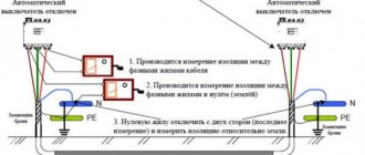
When working with radio equipment, sometimes it is necessary to measure not only the activity, but also the electrical reactance (inductance and capacitance). For measurements, the indirect method of using a multimeter is used, and more accurate values are obtained using the bridge method.
The indirect method is the simplest to implement, since it does not require additional switching circuits. One requires three separate instruments: an ammeter, a voltmeter and a wattmeter. If you measure the voltage and current in the circuit, you can get the total electrical resistance: Z=U*I After measuring the active power P, you can get the value of the active resistance of an individual element: R= P/I².
Coil
An inductor is a metal or ferrite core around which several turns of copper wire are wound. The element has the following properties:
- Due to inductance, the rate of change of currents is limited.
- As the frequency of the current increases, the coil is able to increase its resistance (skin effect).
- Creates a magnetic field.
- Increases and accumulates tension.
- Creates a phase shift in alternating current.
- Proportional to the speed of current movement, it creates a self-inductive emf.
All these properties are used in the development of radio receivers, frequency generators, testers, magnetometers and other types of complex equipment.
Reactance of the inductor.
When alternating current flows I
in a coil, a magnetic field creates an EMF in its turns, which prevents the current from changing. When the current increases, the EMF is negative and prevents the current from increasing; when it decreases, it is positive and prevents its decrease, thus resisting the change in current throughout the entire period.
U is formed at the terminals of the inductor in antiphase
, suppressing EMF, equal to it in amplitude and opposite in sign.
When the current passes through zero, the amplitude of the EMF reaches its maximum value, which forms a discrepancy in time between the current and voltage of 1/4 of the period.
U is applied to the terminals of the inductor
, the current cannot start instantly due to the counter-emf equal to
-U
, therefore the current in the inductance will always lag behind the voltage by an angle of 90°. The shift at the lagging current is called positive.
Let us write down the expression for the instantaneous voltage value u
based on the emf (
ε
), which is proportional to the inductance
L
and the rate of change of current:
u = -ε = L(di/dt)
. From here we express the sinusoidal current.
Integral of the function sin(t)
will be
-cos(t)
or an equal function
sin(t-π/2)
.
The differential dt
of the function
sin(ωt)
will leave the sign of the integral by the factor 1
/ω
.
As a result, we obtain an expression for the instantaneous value of the current with a shift from the voltage function by an angle π/2
(90°).
In this case, for the root-mean-square values of U
and
I,
As a result, we have a dependence of sinusoidal current on voltage according to Ohm’s Law, where in the denominator instead of R
expression
ωL
, which is the reactance:
The reactance of inductances is called inductive.
Design and varieties
All types of inductors have the same design, regardless of their application. The features introduced to obtain individual parameters affect the type of part.
- Solenoid. Component with increased overall length of winding wire. The winding is larger than the diameter of the part.
- Toroidal. In such a coil, the solenoid is made in the shape of a “torus”.
- Multilayer type, has several rows of winding.
- Sectioned. The winding has several divided sections, sometimes made of wire of different sections. The best known coil of this type is the transformer or choke.
- Universal, can combine several winding options at once.
Regardless of design, all coils operate on the same principle.
Resistance measurement and calculation formula
The active resistance of the inductor can only be measured in a de-energized state. This is done using a multimeter.
- The multimeter must be switched to ohmmeter mode.
- Connect the red measuring probe to the first output of the coil.
- Connect the black test lead to the second output.
- The device will only show the active resistance of the winding.
Using a tester, you can only determine the integrity of the turns. If the element is connected to a live circuit, then the resistance value is found by a simple calculation using the formula: Z=U/I.
It will be interesting➡ What is the transformation coefficient - what does it depend on and what does it show?
To calculate using this formula, using a tester, first determine the value of current (I) and voltage (U). Active resistance is measured in Ohms.
Knowing the formula for calculating active and inductive resistance, the total resistance of the element can be found using the formula:
Z=2×(R×R+XL×XL)
In this expression, R is resistance and XL is inductive.
Inductive reactance
The alternating magnetic field created during energy transfer becomes a source of reactance of this type. The inductive option mainly depends on the characteristics of the current passing, the diameter and distance between the wires.
The resistance itself is usually classified as follows:
- depending on current parameters and material - internal;
- due to the geometric features of the line - external. In this case, this indicator will be a constant value, independent of any other factors.
Cable factories always indicate information about inductive reactance in their catalogs.
This parameter is usually determined by the following expression:
in which the inductive indicator for 1 km of wire is , and L is the length.
X kilometer section is calculated using the following formula:
Where: Dav – average distance along the central axis of the existing wires, mm; d – diameter of the working conductor, mm; μt – relative magnetic permeability.
Coil resistance
Active resistance is determined by the ohmic characteristics of the winding wires. When operating at low frequencies, the ohmic resistance does not depend on frequency. In powerful devices, it is necessary to take into account the proximity effect, which consists in the fact that currents and the magnetic field they generate cause displacement of the current in the wires of adjacent turns. As a result, the effective usable cross-section of the wire decreases and its ohmic resistance increases.
Note! At high frequencies, the skin effect appears, which consists in the fact that the current is displaced into the surface layers of the wire. As a result, the usable cable cross-section is reduced. To reduce the skin effect, instead of one conductor, a bundle of several thinner ones is used - Litz wire, or the surface of the wire is coated with a layer of silver, since it has the lowest resistivity.
Skin effect
In powerful electromagnetic systems (particle accelerators), to reduce active resistance, the property of superconductivity is used - the complete disappearance of resistance when some materials are cooled below a critical temperature.
Litz wire
In many cases where inductors are used, the effect of winding resistance must be taken into account. This parameter can have a negative effect not only by reducing the quality factor, but also cause increased heating of the winding conductors when the device operates with high currents.
Inductive reactance
It occurs in circuits where there are some sort of electromagnets that influence the magnetic field of the electrical circuit. They are also called inductors. Inductors have low electrical impedance at low frequencies and high electrical impedance at high frequencies.
Different inductors. Note the commonality
designs - a copper wire is wound around a magnet, forming a coil.
Determination of active resistance of wires
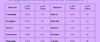
It is easiest to determine the active resistance of wires using reference data compiled on the basis of GOST 839-80 - “Bare wires for overhead power lines”, tables 1 - 4. You can find these tables directly in GOST itself, I will give just a few. It is not recommended to use all known formulas for determining active resistance [L1. p.18], this is due to the fact that the actual cross-section differs from the nominal cross-section, the wires were produced at different times, according to different GOSTs and specifications, and the values of conductivity (ρ) and resistivity (γ) are different:
Where:
- γ – the value of specific conductivity for copper and aluminum wires at a temperature of 20 °C is accepted: for copper wires – 53 m/Ohm*mm2; for aluminum wires – 31.7 m/Ohm*mm2;
- s – nominal wire (cable) cross-section, mm2;
- l – line length, m;
- ρ – the resistivity value is accepted: for copper wires - 0.017-0.018 Ohm*mm2/m; for aluminum wires – 0.026 - 0.028 Ohm*mm2/m, see table 1.14 [L2. p.30].
The active resistance of steel wires cannot be calculated mathematically. Therefore, I recommend using appendices P23 - P25 [L1.] to determine active resistance. p.80,81].