Do-it-yourself inverter welding is very simple
Inverter welding is a modern device that is widely popular due to the light weight of the device and its dimensions. The inverter mechanism is based on the use of field-effect transistors and power switches. To become the owner of a welding machine, you can visit any tool store and acquire such a useful thing. But there is a much more economical way, which is due to the creation of inverter welding with your own hands. It is the second method that we will pay attention to in this material and consider how to do welding at home, what is needed for this and what the diagrams look like.
Advantages of a welding machine from a computer power supply
A homemade welding machine will be small and light. It is perfect for home welding; it is convenient to weld with two or three electrodes, without experiencing problems with “flashing lights” and without worrying about the electrical wiring. The power supply for such a welding machine can be any household outlet, and during operation such a device will practically not spark.
By making a welding inverter with your own hands, you can significantly save on purchasing a new device, but this approach will require a significant investment of both effort and time. After assembling the finished sample, you can try to make your own changes to the welding machine from the computer unit and its circuit, to make lightweight models of greater power. And by making such devices for friends to order, you can provide yourself with a good additional income.
Read also: Container for cyclone filter
Features of the inverter operation
An inverter-type welding machine is nothing more than a power supply, the one that is now used in modern computers. What is the operation of the inverter based on? The following picture of electrical energy conversion is observed in the inverter:
1) The voltage consumed from the network is converted to DC.
2) Current with a constant sinusoid is converted into alternating current with a high frequency.
3) The voltage value decreases.
4) The current is rectified while maintaining the required frequency.
A list of such electrical circuit transformations is necessary in order to be able to reduce the weight of the device and its overall dimensions. After all, as you know, old welding machines, the principle of which is based on reducing the voltage and increasing the current on the secondary winding of the transformer. As a result, due to the high current value, the possibility of arc welding of metals is observed. In order for the current to increase and the voltage to decrease, the number of turns on the secondary winding decreases, but the cross-section of the conductor increases. As a result, you can notice that a transformer-type welding machine not only has significant dimensions, but also a decent weight.
To solve the problem, an option was proposed for implementing a welding machine using an inverter circuit. The principle of the inverter is based on increasing the frequency of the current to 60 or even 80 kHz, thereby reducing the weight and dimensions of the device itself. All that was required to implement an inverter welding machine was to increase the frequency thousands of times, which became possible thanks to the use of field-effect transistors.
Transistors provide communication with each other at a frequency of about 60-80 kHz. The transistor power supply circuit receives a constant current value, which is ensured by the use of a rectifier. A diode bridge is used as a rectifier, and capacitors provide voltage equalization.
Alternating current that is transferred after passing through transistors to a step-down transformer. But at the same time, a coil that is hundreds of times smaller is used as a transformer. Why a coil is used, because the frequency of the current that is supplied to the transformer is already increased 1000 times thanks to field-effect transistors. As a result, we obtain similar data as with transformer welding, only with a large difference in weight and dimensions.
Welding current indication
Even if a digital current setting indicator is installed on the inverter, it does not show its real value, but a certain service value, scaled for visual display. The deviation from the actual current value can be up to 10%, which is unacceptable when using special brands of electrodes and working with thin parts. You can get the actual value of the welding current by installing an ammeter.
A digital ammeter of the SM3D type will cost around 1 thousand rubles; it can even be neatly built into the inverter housing. The main problem is that measuring such high currents requires a shunt connection. Its cost is in the range of 500–700 rubles for currents of 200–300 A. Please note that the type of shunt must comply with the recommendations of the ammeter manufacturer; as a rule, these are 75 mV inserts with an intrinsic resistance of about 250 μOhm for a measurement limit of 300 A.
The shunt can be installed either on the positive or negative terminal from inside the housing. Typically, the size of the connecting bus is sufficient to connect an insert about 12–14 cm long. The shunt cannot be bent, so if the length of the connecting bus is not enough, it must be replaced with a copper plate, a pigtail of cleaned single-wire cable, or a piece of welding conductor.
The ammeter is connected with measuring outputs to the opposite terminals of the shunt. Also, for the digital device to operate, it is necessary to supply a supply voltage in the range of 5–20 V. It can be removed from the fan connection wires or found on the board at points with potential for powering control chips. The ammeter's own consumption is negligible.
What is needed to assemble an inverter
To assemble inverter welding yourself, you need to know that the circuit is designed, first of all, for a consuming voltage of 220 Volts and a current of 32 Amps. After energy conversion, the output current will increase almost 8 times and reach 250 Amperes. This current is sufficient to create a strong seam with an electrode at a distance of up to 1 cm. To implement an inverter-type power supply, you will need to use the following components:
1) A transformer consisting of a ferrite core.
2) Winding of the primary transformer with 100 turns of wire with a diameter of 0.3 mm.
3) Three secondary windings:
— internal: 15 turns and wire diameter 1 mm;
- medium: 15 turns and diameter 0.2 mm;
— external: 20 turns and diameter 0.35 mm.
In addition, to assemble the transformer, you will need the following elements:
- copper wires;
- fiberglass;
— textolite;
— electrical steel;
- cotton material.
Frame
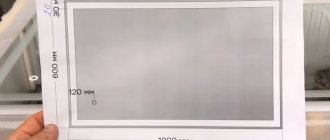
Next, we begin to manufacture the body. Its size should be commensurate with the dimensions of the transformer and plus 70% for the placement of other parts of the inverter. The body itself can be made of sheet steel with a thickness of 0.5-1 mm.
To connect the corners, you can use bolts or use special bending machines to bend the sheet to the desired size. If you place a handle on the case for attaching the inverter to a belt or for ease of transfer, this will greatly facilitate the operation of the device in the future.
In addition, the design of the housing should provide fairly easy access to all parts located inside it. It is necessary to make several technological holes on it for switches, a power button, light signaling of operability, as well as cable connectors.
Welding inverter generator circuit
What does an inverter welding circuit look like?
In order to understand what an inverter welding machine is, it is necessary to consider the diagram presented below.
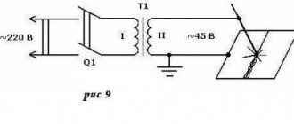
Electrical circuit of inverter welding
All these components must be combined and thereby obtain a welding machine, which will be an indispensable assistant when performing plumbing work. Below is a schematic diagram of inverter welding.
Inverter welding power supply diagram
The board on which the device's power supply is located is mounted separately from the power section. The separator between the power part and the power supply is a metal sheet connected electrically to the unit body.
To control the gates, conductors are used, which must be soldered close to the transistors. These conductors are connected to each other in pairs, and the cross-section of these conductors does not play a special role. The only thing that is important to consider is the length of the conductors, which should not exceed 15 cm.
For a person who is not familiar with the basics of electronics, reading this kind of circuit is problematic, not to mention the purpose of each element. Therefore, if you do not have skills in working with electronics, then it is better to ask a familiar specialist to help you figure it out. For example, below is a diagram of the power part of an inverter welding machine.
Diagram of the power part of inverter welding
Winding the output choke
One of the simplest and at the same time most useful additions to a welding inverter will be the winding of an inductive coil that smoothes out the DC ripples that inevitably remain when the pulse transformer is operating. The main specificity of this idea is that the choke is made individually for each individual device, and can also be adjusted over time as electronic components degrade or when the power threshold changes.
To make a choke you will need nothing at all: an insulated copper conductor with a cross-section of up to 20 mm 2 and a core, preferably made of ferrite. Either a ferrite ring or an armored transformer core is optimally suited as a magnetic core. If the magnetic core is made of sheet steel, it needs to be drilled in two places with an indentation of about 20–25 mm and tightened with rivets in order to be able to cut the gap without any problems.
The choke begins to work starting from one full turn, but the real result is visible starting from 4–5 turns. During testing, turns should be added until the arc begins to stretch noticeably strongly, preventing separation. When it becomes difficult to cook with separation, you need to remove one turn from the coil and connect a 24 V incandescent lamp in parallel with the choke.
Fine-tuning the throttle is done using a plumber's screw clamp, which can be used to reduce the gap in the core, or a wooden wedge, which can be used to increase this gap. It is necessary to ensure that the lamp burns as bright as possible when igniting the arc. It is recommended to manufacture several chokes to operate in ranges up to 100 A, from 100 to 200 A and more than 200 A.
How to assemble inverter welding: step-by-step description + (Video)
To assemble an inverter welding machine, you must complete the following work steps:
1) Housing . It is recommended to use an old computer system unit as a housing for welding. It is best suited as it has the required number of holes for ventilation. You can use an old 10-liter canister in which you can cut holes and place the cooler. To increase the strength of the structure, it is necessary to place metal corners from the system housing, which are secured using bolted connections.
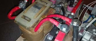
2) Assembling the power supply. An important element of the power supply is the transformer. It is recommended to use 7x7 or 8x8 ferrite as the base of the transformer. For the primary winding of the transformer, it is necessary to wind the wire across the entire width of the core. This important feature entails improved operation of the device when voltage surges occur. It is imperative to use PEV-2 copper wires as wire, and if there is no busbar, the wires are connected into one bundle. Fiberglass is used to insulate the primary winding. On top, after the layer of fiberglass, it is necessary to wind turns of shielding wires.
Transformer with primary and secondary windings for creating inverter welding
3) Power part . A step-down transformer acts as a power unit. Two types of cores are used as a core for a step-down transformer: Ш20х208 2000 nm. It is important to provide a gap between both elements, which is solved by placing newsprint. The secondary winding of a transformer is characterized by winding turns in several layers. It is necessary to lay three layers of wires on the secondary winding of the transformer, and fluoroplastic gaskets are installed between them. It is important to place a reinforced insulating layer between the windings, which will avoid voltage breakdown on the secondary winding. It is necessary to install a capacitor with a voltage of at least 1000 Volts.
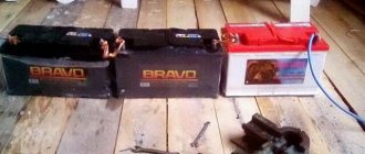
Transformers for the secondary winding from old TVs
To ensure air circulation between the windings, it is necessary to leave an air gap. A current transformer is assembled on a ferrite core, which is connected to the circuit to the positive line. The core must be wrapped with thermal paper, so it is best to use cash register tape as this paper. Rectifier diodes are attached to the aluminum radiator plate. The outputs of these diodes should be connected with bare wires with a cross-section of 4 mm.
3) Inverter block . The main purpose of an inverter system is to convert direct current into high-frequency alternating current. To ensure an increase in frequency, special field-effect transistors are used. After all, it is the transistors that work to open and close at high frequencies.
It is recommended to use more than one powerful transistor, but it is best to implement a circuit based on 2 less powerful ones. This is necessary in order to be able to stabilize the current frequency. The circuit cannot do without capacitors, which are connected in series and make it possible to solve the following problems:
Aluminum plate inverter
4) Cooling system . Cooling fans should be installed on the case wall, and for this you can use computer coolers. They are necessary to ensure cooling of the working elements. The more fans you use, the better. In particular, it is imperative to install two fans to blow over the secondary transformer. One cooler will blow on the radiator, thereby preventing overheating of the working elements - rectifier diodes. The diodes are mounted on the radiator as follows, as shown in the photo below.
Rectifier bridge on the cooling radiator
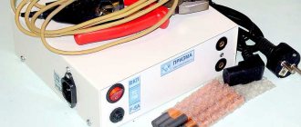
It is recommended to use an auxiliary element such as a temperature sensor.
Photo of the thermostat
It is recommended to install it on the heating element itself. This sensor will be triggered when the critical heating temperature of the working element is reached. When it is triggered, the power to the inverter device will be turned off.
Powerful fan for cooling the inverter device
During operation, inverter welding heats up very quickly, so the presence of two powerful coolers is a prerequisite. These coolers or fans are located on the device body so that they work to extract air.
Fresh air will enter the system thanks to the holes in the device body. The system unit already has these holes, and if you use any other material, do not forget to provide a flow of fresh air.
5) Soldering the board is a key factor since the entire circuit is based on the board. It is important to install diodes and transistors on the board in opposite directions to each other. The board is mounted directly between the cooling radiators, with the help of which the entire circuit of electrical appliances is connected. The supply circuit is designed for a voltage of 300 V. The additional arrangement of capacitors with a capacity of 0.15 μF makes it possible to dump excess power back into the circuit. At the output of the transformer there are capacitors and snubbers, with the help of which the overvoltages at the output of the secondary winding are suppressed.
6) Setting up and debugging work . After the inverter welding has been assembled, several more procedures will need to be carried out, in particular, setting up the operation of the unit. To do this, connect a voltage of 15 volts to the PWM (pulse width modulator) and power the cooler. Additionally connected to the relay circuit through resistor R11. The relay is included in the circuit in order to avoid voltage surges in the 220 V network. It is imperative to monitor the relay’s activation, and then apply power to the PWM. As a result, a picture should be observed in which rectangular areas in the PWM diagram should disappear.
The device of a homemade inverter with a description of the elements
You can judge whether the circuit is connected correctly if the relay outputs 150 mA during setup. If a weak signal is observed, this indicates that the board connection is incorrect. There may be a breakdown in one of the windings, so to eliminate interference you will need to shorten all power supply wires.
Inverter welding in a computer system case
Checking the device's functionality
After all the assembly and debugging work has been completed, all that remains is to check the functionality of the resulting welding machine. To do this, the device is powered from a 220 V power supply, then high current values are set and the readings are verified using an oscilloscope. In the lower loop, the voltage should be within 500 V, but not more than 550 V. If everything is done correctly with a strict selection of electronics, then the voltage indicator will not exceed 350 V.
So, now you can check the welding in action, for which we use the necessary electrodes and cut the seam until the electrode burns out completely. After this, it is important to monitor the temperature of the transformer. If the transformer simply boils, then the circuit has its shortcomings and it is better not to continue the work process.
After cutting 2-3 seams, the radiators will heat up to a high temperature, so after this it is important to allow them to cool down. To do this, a 2-3 minute pause is enough, as a result of which the temperature will drop to the optimal value.
Checking the welding machine
Improved heat dissipation
The first drawback that plagues the vast majority of inexpensive inverter devices is a poor heat removal system from power switches and rectifier diodes. It is better to begin improvements in this direction by increasing the intensity of forced airflow. As a rule, case fans are installed in welding machines, powered by 12 V service circuits. In “compact” models, forced air cooling may be completely absent, which is certainly nonsense for electrical equipment of this class.
Read also: Edge banding machine operating instructions
It is enough to simply increase the air flow by installing several of these fans in series. The problem is that the “original” cooler will most likely have to be removed. To operate effectively in a sequential assembly, fans must have an identical shape and number of blades, as well as rotation speed. Assembling identical coolers into a “stack” is extremely simple; just tighten them with a pair of long bolts along diametrically opposite corner holes. Also, do not worry about the power of the service power supply; as a rule, it is enough to install 3–4 fans.
If there is not enough space inside the inverter housing to install fans, you can install one high on the outside. Its installation is simpler because it does not require connection to internal circuits; power is removed from the power button terminals. The fan, of course, must be installed opposite the ventilation louvers, some of which can be cut out to reduce aerodynamic drag. The optimal direction of air flow is towards the exhaust from the housing.
The second way to improve heat dissipation is to replace standard aluminum radiators with more efficient ones. A new radiator should be selected with the largest number of fins as thin as possible, that is, with the largest area of contact with air. It is optimal to use computer CPU cooling radiators for these purposes. The process of replacing radiators is quite simple, just follow a few simple rules:
- If the standard radiator is isolated from the flanges of the radio elements with mica or rubber gaskets, they must be preserved when replacing.
- To improve thermal contact, you need to use silicone thermal paste.
- If the radiator needs to be trimmed to fit into the case, the cut fins must be carefully processed with a file to remove all burrs, otherwise dust will accumulate on them abundantly.
- The radiator must be pressed tightly against the microcircuits, so you first need to mark and drill mounting holes on it; you may need to cut a thread in the body of the aluminum base.
Additionally, we note that there is no point in changing the piece heatsinks of separate keys; only the heat sinks of integrated circuits or several high-power transistors installed in a row are replaced.
How to use a homemade device
After connecting a homemade device to the circuit, the controller will automatically set a certain current strength. If the wire voltage is less than 100 Volts, this indicates a malfunction of the device. You will have to disassemble the device and recheck the correct assembly again.
Using this type of welding machine, you can solder not only ferrous, but also non-ferrous metals. In order to assemble a welding machine, you will need not only knowledge of the basics of electrical engineering, but also free time to implement the idea.
Inverter welding is an indispensable thing in any owner’s garage, so if you have not yet acquired such a tool, then you can make it yourself.