Due to frequent complaints about the quality characteristics of modern radios that are built into music centers, it is necessary to use additional external antennas and amplifiers.
In this case, an FM antenna for a music center comes to the rescue, and it is quite possible to make it yourself from scrap materials. The problem of poor signal reception is relevant for remote villages or when traveling.
Therefore, a self-made antenna for fm radio can help the radio operate without failures.
Important! The higher the FM antenna is positioned in relation to the listener, the better the quality of signal reception will be.
FM antennas for music centers - what are they?
An FM radio antenna is a device designed to improve the quality of radio reception and broadcasts.
The main function of such antennas is to receive a signal in cases where the desired station cannot independently receive a high-quality radio signal.
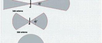
Important! The types of all antennas are determined by their radiation patterns.
There are two types of PM antennas: active and passive. All types are characterized by the region of space where the maximum indicator of the main radiation of the received or transmitted signal is located.
Whip structures are considered passive; an active radio antenna is an improved model that has an amplifying counterweight.
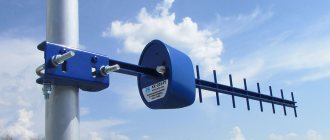
Highly directional FM antennas are worth highlighting in a separate category - they distribute a radio signal in a strictly defined area without wasting it, and, accordingly, saving electricity.
Best models
There are practically no popular models among amplifiers. Such devices are installed extremely rarely, since a modern multimedia system allows you to play music from various media. When determining a popular model, the following points are taken into account:
- Device cost. A proposal of domestic origin costs 1000 rubles. Do not forget that the price determines the basic properties of the device.
- Length of service life. Installing an amplifier involves changing the receiver connection circuit. Therefore, you should connect a device that can last for several years.
- Reliability. The device must operate under various operating conditions: voltage changes, temperatures, humidity and other situations.
- Signal level. This indicator can vary over a wide range.
There are models of domestic and foreign origin on sale. Models of foreign origin are more popular; domestic ones are several times cheaper.
Triad 304
A domestic car antenna amplifier called “Triad 304” costs 650 rubles. There are various reviews on the Internet, many of them negative. The positive points are the following:
- Low price.
- Good build quality.
- It is possible to turn off the device if the signal is strong.
- Optimal functionality.
Such an amplifier does not last for a long period. Therefore, they often give preference to other models from foreign manufacturers.
Prology TFB-100
An antenna amplifier of foreign origin is more popular due to its attractive performance characteristics. The Prology tfb-100 model has the following features:
- The device can simultaneously operate with several antennas.
- High-quality signal amplification is carried out in the digital and analog range.
The device in question is small in size, so installation does not pose any problems.
Master kit
When looking for a universal version, the Master Kit car antenna amplifier is selected. It has the following features:
- The applied scheme is two-stage.
- There are special kits that are easy to assemble. To do this, it is enough to have a soldering iron and the required consumables.
The cost of such sets is relatively low. Therefore, they are chosen to improve the quality of radio signal reception in various bands.
Operating principle
The radio signal arriving at the FM antenna is amplified, received or transmitted.
The operating principle of the device can be explained in more detail as follows:
- Radio waves in the form of an alternating electromagnetic field arrive at the antenna.
- It produces in response multidirectional currents that appear due to the reception of radio waves.
- Coincidences of frequencies and currents appear - the frequency of the radiation of the transmitter with an alternating field, the current at the receiver with the current at the transmitter.
- If the wavelength is a multiple of the antenna dimensions, a resonance appears at the receiver frequencies, which amplifies the signal, significantly improving it.
We recommend reading: Types of resistors, what they are needed for, how to check, designation, connection
On a note! Strict compliance with the antenna height and wavelength is necessary - this not only improves the signal, but allows you to accurately calculate the reception frequency.
Antenna connection
DIY Mimo 4g lte antenna
The antenna for the radio receiver is connected in several ways:
- Direct: the antenna (usually telescopic antennas) is an integral part of the receiving radio device, while the “ground” phase is its body itself. The (active) resistance with such a connection reaches thirty ohms, and the reactive one is removed by altering the resonance circuit. Such antennas are not symmetrical. The grounding must be reliable (the length of the bare wire must exceed 1/10 wavelength), otherwise interference due to loop radiation is possible;
- With non-resonant power supply: a transmission line is used for directional transmission of radio waves, and its characteristic impedance must be equivalent to the antenna impedance. This connection allows you to get rid of losses and provide the best radio signal level;
Important! The excess cable between the FM antenna and the radio receiver should be cut, because each additional meter greatly reduces the receiver's sensitivity. After matching the resistance, bringing it closer to 50 Ohms, radio signal reception improves significantly.
- With the resonant type of power supply of communication lines, the ease of passage of radio waves directly depends on the length of the wave itself. For such antennas, feeders of half the wavelength (or multiples) are chosen, and the wave resistance is no longer so important, the antenna is matched. The frequency that an FM antenna perceives is the carrier frequency, quite often these are sine waves with a leading frequency of 50 hertz (harmonics).
FM antenna design for receiver
For household radio broadcasting, an FM antenna is used with frequencies from 88 to 108 Megahertz on ultrashort three-meter waves.
An indoor antenna usually consists of:
- rotating devices or hardware antennas;
- structures with traveling waves;
- linear devices.
Structurally, antennas are classified according to their radiation pattern - highly directional (narrowly directional) or circular. The radio bandwidth allows for wideband or narrowband devices.
It is worth considering that the design of the receiver may affect the quality of the signal due to certain difficulties in setting up one type or another.
Amateur band 145 MHz
Stationary VHF antennas are relatively simple to manufacture. The basis is the circuit of a quarter-wave vibrator. The range products are equipped with a relatively wide bandwidth; precise tuning to the frequency is not required. Let's look at examples of designs:
- For the simplest way to make a receiving antenna - outdoors, at home, anywhere - you will need a T-tee. The perpendicular branch is supplied with a coaxial, the other two - with a twisted spire of the radio station, counterweights (analogous to the ground of the VHF range).
- A straight corner with square sides 4 cm is attached to the outer wall, counterweights 5 cm long are bolted to the edges of the horizontal platform, and a connector for the antenna is equipped in the middle. Since the coaxial cable outlet leading to the structure is the main cause of signal loss, the length of the segment must be minimal. It will be difficult to make gold connectors yourself; cleaning the existing steel ones and wiping them with alcohol, increasing sensitivity, is a must. Since a standard amateur radio antenna inserted into the pad socket has a resistance of about 40 ohms, the connection is made with a 50 ohm coaxial cable. Finally, the impedance of the remote antenna is adjusted by rotating the counterweights. To replace the factory antenna, you can use a piece of copper wire with a diameter of 1-2 mm and a length of 48 cm.
- If the original antenna for the VHF receiver is broken, replace it with a 48 cm long piece of 50 Ohm coaxial cable with the screen removed. Avoid exposing the vein. You can replace the piece of wire with the product in the previous method.
- We get a more complex version by winding half a meter of copper wire around the internal dielectric of the coaxial. The difficulty lies in matching the resistance of the resulting homemade design with the characteristic impedance of the radio station. After debugging, secure the turns with insulating tape.
How to make an FM antenna yourself
The simplest indoor antenna for a do-it-yourself music center:
- Prepare tools - copper wires, knife, pliers.
- Cut off a portion of the wire suitable for winding onto the main element.
- Remove the insulation along the entire length.
- The wire is wound around an antenna or plastic base and the signal is caught.
- They strengthen the structure in the place where the correct technique works.
On a note! This method is suitable for home music centers and does not guarantee high signal quality.
Types of antennas
Any device that receives radio waves has a sensitivity threshold. If the received signal is lower than this, the sound volume and quality will be poor. The radio wave weakens when moving far away from the transmitting station or due to deteriorating weather. This is especially true for the FM and VHF bands due to the characteristics of wave transmission. To overcome these difficulties, strengthen and improve the signal quality, any radio needs an antenna. Their design features and dimensions are determined by the range of the receiver: there are multi-kilogram antennas with coverage of thousands of square meters. km and simple homemade crafts in the form of wire above the ground.
The whole variety of antennas for radio stations is divided into directional and non-directional, as well as mobile and stationary. Directional ones work on the principle of connecting point to point or point to many points within 50-100 meters. Non-directional ones have coverage over the entire area around them.
There are also such radio antennas as:
- Rod - in the form of a regular rod or a rounded shape;
- Wire – curved in various required positions;
- On once fashionable boomboxes and music centers you can find telescopic antennas - folding structures made of metal rods, reminiscent of telescopes;
Telescopic antenna
- A retractable antenna is available on almost every car; its advantage is that such a retractable structure can be installed anywhere in the car (roof, fender, etc.), the receiving element is a removable rod with anti-noise winding, which allows you to make the radio sound clear and loud even at high driving speeds. The rod goes into a plastic casing, where there is a stainless steel spring, which retracts the antenna into place when it is deflected in the direction of travel.
Regardless of the type or type of radio antenna, their operating principles are the same.
Note! Quite often, the quality of a radio signal does not depend on the type and condition of the antenna for a radio receiver or music center, but on the technical capabilities of these devices themselves with their receiving chips.
Options for homemade designs
How to make a radio antenna with your own hands? There are quite a lot of different methods that are available for independent implementation at home. For example, the following options are often found:
I'm making an FM antenna.
- foil antenna;
- rod device;
- omnidirectional FM antenna made of coaxial cable;
- wire structure;
- pipe antenna.
Half-wave antenna frequency 145 MHz
The quarter-wave homemade VHF antennas discussed above are not the only way out of the situation. The advantage is low wave impedance; half-wave options have the right to exist. A piece of wire with a diameter of 1 mm and a length of 103 cm has a resistance of 1 kOhm, 20 times higher than a standard coaxial (50 Ohm).
To reconcile the difference in values, a U-shaped contour is used. The future wire antenna should be cut several centimeters shorter/longer than 103 cm. It will slightly increase losses due to an increase in the reactive component of the impedance, significantly reducing the real part of the impedance, and the matching device will be easier to configure.
The filter inductance is connected in series with the antenna and is formed by 5 turns of wire with a diameter of 1 mm, wound in increments of 2 mm on a mandrel with a diameter of 6 mm. Trimmer capacitors KPVM-1 (5-14 pF) are connected with one plate to the ground on both sides of the coil.
The antenna for the VHF radio is adjusted by measuring the SWR and field strength. The minimum of the first parameter coincides with the maximum of the second. Otherwise, the length of the antenna is shortened and measurements are taken again. It is recommended to initially select a wire length of 102 cm, gradually cut it from the upper end, selecting the optimal value.
The process of making a homemade antenna
At the initial stage, you need to select the necessary tools, without which you will not be able to make a device for fm radio on your own.
From a large number of methods, you can choose the most suitable one, taking into account your own strengths and capabilities.
We recommend reading: Thyristors: principle of operation, testing and characteristics
On a note! The manufacture of an antenna in this case is discussed using one of the examples of creating high-quality antennas that can be used for any household radio receivers.
Tools:
- Solder, rosin, soldering iron and soldering flux;/.
- Thin copper wire.
- Dielectric base - for example, chipboard sheets, boards, etc.
- Fasteners - nuts, screws, screws and others.
- Suitable coaxial cable and plug.
- Standard locksmith tool.
- Waterproof paint or varnish.
How to make an antenna based on a finished drawing:
- The wire is given the required shape.
- Taped to a dielectric base.
- Solder the cable.
- The braid is connected to one end of the device, the central core to the other.
- The cable and dipole antenna are connected in the same way.
- The device is painted.
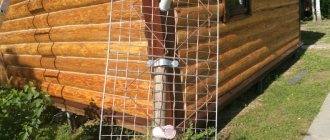
- After the paint has dried, the antenna is installed on the pipe, the cable on the support.
- The other end of the cable is connected to the plug and the antenna is raised as high as possible.
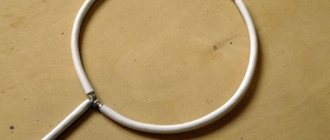
The simplest FM antenna for a DIY receiver
The description describes a method for making a loop antenna. Other devices differ in shape and materials, but the principle of operation is the same for all.
ANTENNA AMPLIFIER FOR CAR RADIO
All car enthusiasts have radios in their cars, but not all radios pick up the radio well. Only expensive devices are equipped with serious receivers with good UHF, capable of receiving weak FM stations. Most cheap car radios only work acceptably in the city, so it makes sense to equip them with an antenna amplifier. There are two options here - buy a ready-made industrial one or solder it yourself.
Antenna amplifier Ratex
For those who have some amateur radio skills, a couple of circuits of such amplifiers are offered.
The input coil L1 consists of four turns of enameled copper wire (frameless) on a mandrel more than 5 mm in diameter. Coil L2 is similar to L1, but has only three turns. The pinout of the 2SC2570 is shown in the diagram.
Rapid deployment antenna on CB (27.200)
The authorship of the antenna design belongs to RX3AKT. In essence, this antenna is a half-wave vibrator powered from the end and matched with a cable loop. In terms of efficiency, such a coaxial antenna is not much inferior to factory analogues from the same Sirio, and is much simpler and more compact to manufacture. The antenna was conceived as a traveling option, since it is very light and compact, but it can also be used stationary.
What you need to make a rapid deployment antenna
For manufacturing you will need 7 meters of RG-58 cable (antenna fabric + matching part), a piece of RG-58 cable of arbitrary length to connect the antenna to the walkie-talkie, a PL-259 or SO-239 connector, a few centimeters of heat shrink of a suitable diameter (for example 7mm and 12mm), instant glue, a sharp knife, a soldering iron with solder and rosin, and 40 minutes of free time. For modeling, I recommend using the crappiest cable on the market, namely REXANT. These guys make great solder and other radio mounting stuff, but their cable is truly terrible, but it is cheap and can be used for antenna building experiments.
Antenna design
The antenna consists of 3 parts. The part is 520 cm long; this antenna sheet is the radiating part. The part 152 cm long is the matching part, it represents a capacitance, the part 23-24 cm long also belongs to the matching part and represents inductance. During the assembly process, it is easiest to use the image from the title of the article. The points in the figure are solder joints.
1. Take the RG-58 cable and cut a piece 7 meters long.
2. Strip the braid on the cable from both ends, approximately 1-1.5 cm.
3. Remove the foil, if any, and twist the central core with the cable screen.
4. Carefully solder the twist of the central core and screen.
5. Next, measure 23 cm from one of the ends of the cable and make a cut in the cable braid, but so as not to damage the screen. We retreat another 2 centimeters (25cm) from the cut and make another cut. Our task is to remove the PVC cable braid without damaging what is underneath it.
We remove the braid and foil, and move the screen to one side and cut it in half. Let's leave it alone for now, we'll come back to this later.
6. We measure 152 cm from the area with the braid removed, and just as in point 5, cut off a part of the braid about 1.5-2 cm wide from the cable. After this, cut the screen from the short part (23 cm + 152 cm) so that on the short part the screen protruded beyond the braid minimally. Remove the foil.
7. Using a sharp knife, remove half of the polyethylene protecting the central core, so as not to damage it and not completely cut the fabric in half. We tin the central core and the screen and solder them to each other.
8. After the soldering area has cooled and the polyethylene has hardened, you need to seal the connection. To do this we use Moment glue. Coat the connection generously, especially the soldering area and the cut ends of the braid. But without fanaticism. Be sure to let the glue dry a little and only then move on to the next step.
9. We put a heat-shrinkable tube with a diameter of 6-7 mm on top and shrink it (best by heating it with a hairdryer). On top, you can apply another layer of heat shrink, so to speak, for strength and greater length. After the glue cools and dries, a completely strong and airtight connection is obtained.
10. Return to the 23 cm piece. Similarly to point 7, remove the layer of polyethylene up to the central core and solder the reduction cable. It must first be cleaned, as in point 2. Solder the central core of the reduction cable to the central core at the point 24 cm.
11. We put heat shrink with a diameter of 8-10 mm on top and place it on both central cores.
12. We solder the screens of part of the 23 cm cable, part of the 152 cm cable and the reduction cable at one point.
13. Coat the soldering area generously with glue, let it dry and put heat shrink with a diameter of 12mm on top. We sit down.
14. On the ends of the antenna (23 cm and the radiating part), also coated with moment, we put trem-shrink on it and seat and seal the ends.
15. Solder the connector for the radio station to the end of the reduction cable and... Done.
Field tests
In progress…
Good luck to everyone, 55, 73!