During operation of power equipment, it is constantly exposed to current overloads, which reduce its durability. Protection in such situations is a thermal relay for the electric motor, which turns off the power supply when unusual circumstances arise.
We suggest you understand the design, operating principle, types and nuances of connecting protective devices. In addition, we will tell you what parameters and characteristics should be taken into account when choosing a thermal relay.
Selecting a thermal relay for an electric motor
The main requirement for thermal regulators of electric motors is that the device rating corresponds to the current of the device to be protected. At the same time, the relays themselves are also provided with short-circuit protection, which is why fuses must be included in any connection diagram.
Table for correct selection of electric motor thermal relay according to current rating
If the thermal protection of the motor is not related to any special requirements, the relay can easily be selected according to the table presented above with the most appropriate technical parameters.
Also, the protective device is selected according to the highest operating current of the relay, which does not exceed the rated current of the electric motor to be protected. Despite this, it is recommended to select a relay such that its installation current is slightly higher than the motor rating.
It must be borne in mind that it is possible to adjust the relay current with a large margin in one direction or another - this ensures the most adjustable and effective protection.
Connection diagram
The temperature relay is connected to the terminals using pin contacts. After connection, you should adjust the triggered settings using the regulator wheel in accordance with the value of the current in the network.
The control panel is equipped with a “Test” button, which is necessary to determine the operability of the device by simulating the operation of the protection. A red button with the inscription “Stop” is used to force the contact to open. The power going to the contactor coil is blocked and therefore the load is blocked.
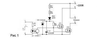
Schematic diagram for connecting thermal relays in electric motors of any modifications
The circuit shown in the figure is used to control an electric motor using a magnetic starter. The power contacts are connected to only two phases, the third is closed directly on the motor.
Review of manufacturers
There are many manufacturers producing thermal relays in different countries. Several of the most popular models are presented in the table.
| Model | Manufacturer | Current rating | Approximate cost, rub. |
| RT 1307 | KS | 1.6-2.5A | 230 |
| RTI-5371 | IEK | 90-120A | 2750 |
| RTN-1316 | TDM | 9-13A | 350 |
Voltage drop and phase loss
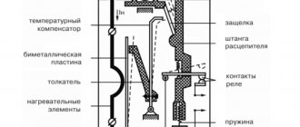
A fully loaded induction motor running at reduced voltage will heat up quickly. If it has a built-in thermal sensor, thermal protection will work. If there is none, undervoltage protection is required. For these purposes, relays are used that are activated when the voltage drops and send a signal to turn off the engine. In the diagram below this is RN.
Restoring the initial protection state is usually performed manually or automatically, but with a time delay for each motor in a group. Otherwise, a simultaneous group start after restoration can again cause a repeated decrease in the voltage in the network and a new shutdown.
Special protection against phase loss, that is, against operation on only two phases, the PUE provides only in such drives where consequences that are unacceptable in severity are possible. It is economically feasible not to manufacture and install such protection, but to eliminate the reasons leading to this mode of operation.
The latest technical solutions in the construction of electric motor protection are automatic circuit breakers with air arc extinguishing. Some models combine the capabilities of a switch, contactor, maximum and thermal relay and perform the corresponding protective functions. In such a machine, the contacts are opened by a powerful charged spring. Its release occurs depending on the type of actuator - electromagnetic or thermal.
Nuances when installing the device
The response speed of the thermal module can be affected not only by current overloads, but also by external temperature indicators. The protection will work even in the absence of overload.
It also happens that, under the influence of forced ventilation, the engine is subject to thermal overload, but the protection does not work.
To avoid such phenomena, you need to follow the recommendations of specialists:
- When choosing a relay, focus on the maximum permissible operating temperature.
- Install the protection in the same room as the protected object.
- For installation, choose places where there are no heat sources or ventilation devices.
- You need to configure the thermal module based on the actual ambient temperature.
- The best option is to have built-in thermal compensation in the relay design.
An additional option for the thermal relay is protection in the event of a phase or complete power supply failure. For three-phase motors this point is especially relevant.
The current in a thermal relay moves sequentially through its heating module and on to the motor. Additional contacts are connected to the starter winding
If there is a problem in one phase, the other two take on a larger current. As a result, overheating quickly occurs, and then shutdown. If the relay does not operate effectively, both the motor and the wiring may fail.
Operating principle of the device
Performing a protective function, the circuit breaker disconnects the power supply circuits. A thermal relay differs from it in that when the load is exceeded, it simply issues a control signal. With such protection, small currents are switched in one control circuit.
In the circuit in front of the thermal relay there is a magnetic starter. When the circuits are opened in an emergency, there is no need to duplicate the operation of the contactor. Consequently, no material is consumed for the manufacture of power contact groups.
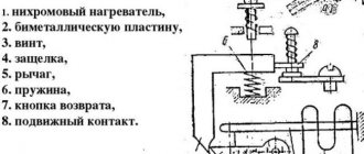
The most popular are devices equipped with bimetallic plates. The plate itself consists of two similar elements.
One of them has a significant temperature coefficient, while the other has a slightly smaller one. These two components fit tightly together.
Since the components of a bimetallic strip are made of a pair of dissimilar metals having unequal expansion coefficients, heating causes it to bend and interact with the contacts
Such rigid fastening is ensured by welding or hot rolling. Due to the fact that the plate is fixed motionless, when heated, it bends towards the element with a lower temperature coefficient. This principle is taken as the basis when creating thermal relays.
In their production, chromium-nickel steel and non-magnetic steel are used, which have a high temperature coefficient. Invar, a compound of nickel and iron, is used as a material with a low value of this parameter.
A thermal relay operates according to this scheme. The loose end of the bimetallic plate, when it bends, affects the contacts of the thermal relay (+)
The bimetal plate is heated by load currents. They most often flow through a special heater. There is also combined heating, in which, in addition to the heat given off by the heater, the bimetal is also heated by the current passing through it.
Principle of operation
Having become familiar with the design and types of devices, it is necessary to understand the operating principle of a thermal relay. The manufacturer installs a plate with technical characteristics on each electric motor. One of the most important among them is the rated operating current. Today there are many units in use, during startup or operation of which this value can be significantly exceeded.
If overloads are observed over a long period of time, overheating of the coils, destruction of the insulating layer and subsequent failure of the motor is possible. Protective TRs are capable of influencing the control circuit by opening contacts or giving a warning signal to maintenance personnel. The devices are mounted in the power circuit in front of the engine in order to be able to control the current passing through the unit.
When setting up the protective device, the parameters are set higher than the nominal nameplate value by 10 to 20%. The issue of setting up the relay must be approached responsibly, since disconnection of the circuit during an overload does not occur instantly. Depending on various factors, this may take 5-20 minutes.
| Category: My articles | Added by: bumer68 (02/16/2017) |
Thermal protection
A thermal relay is an alternative way to protect an electric motor with a certain operating inertia. The operating principle is based on the use of a bimetallic plate, which is heated by the current of the motor windings. Deformation of the plate triggers the contacts necessary to turn off the engine.
The reliability of such protection depends on the similarity of thermal processes in the relay and in the motor. This is only possible if there is a sufficiently long break between turning the engine on and off. The environmental conditions for the motor and for the thermal protection elements must be the same.
The response speed of thermal relays is lower, the greater the current flowing through the heating elements or the plate itself, depending on the design. For large current values in the windings of an asynchronous motor, the connection is made using current transformers. There are models of magnetic starters with thermal relays built into them.
The main electrical parameters are
- Rated voltage. This is the maximum network voltage allowed for using the relay.
- The rated current at which the relay operates for a long time and does not trip.
Thermal protection is not able to respond to short-circuit currents and unacceptable short-term overloads. Therefore, it must be used in conjunction with at least fuses.
A more advanced type of protecting an electric motor from unacceptable heating is a circuit using a special heat sensor. Such a thermal sensor is located on the engine itself in one place or another. Some engine models have a built-in bimetallic sensor - a contact connected to the protection.
Advantages of the device
At its core, a thermal relay is an automatic device for disconnecting electrical equipment from the power supply. But unlike a simple on/off automatic switch, an electrothermal relay has the following significant advantages:
- the ability to adjust the time and moment of operation depending on the overload current and the duration of its effect on electrical equipment;
- different switching options: remote installation in electrical panels or direct installation on magnetic starters.
Other advantages of thermal relays include small size, weight and, of course, cost, as well as simplicity of design and high operational reliability. A certain disadvantage of the device is the need for periodic adjustments and verifications.
Selecting a thermal relay for an electric motor
The main requirement for thermal regulators of electric motors is that the device rating corresponds to the current of the device to be protected. At the same time, the relays themselves are also provided with short-circuit protection, which is why fuses must be included in any connection diagram.
Table for correct selection of electric motor thermal relay according to current rating
Tip #1: You should determine in advance the conditions in which the thermal relays will operate. If the engine is most likely to be operated in emergency conditions not associated with an increase in its electricity consumption, then in such cases the relays will not be able to provide effective protection and will simply be useless.
If the thermal protection of the motor is not related to any special requirements, the relay can easily be selected according to the table presented above with the most appropriate technical parameters.
Also, the protective device is selected according to the highest operating current of the relay, which does not exceed the rated current of the electric motor to be protected. Despite this, it is recommended to select a relay such that its installation current is slightly higher than the motor rating.
It must be borne in mind that it is possible to adjust the relay current with a large margin in one direction or another - this ensures the most adjustable and effective protection.
Questions and answers on electric motors
Question-and-answer session on electric motors for variable-frequency drives. Before the words “Read more,” part of the questions and answers is given.
-I have a regulation range of 1:10, is a regular industrial one
electric motor for operation with a frequency converter?
- Conditionally
suitable.
At frequencies below 25Hz
the electric motor
must
operate
in intermittent mode with duty cycle = 25%
due to the insufficient cooling capacity of the fan. For eight or more pole electric motors, this value can be increased to 30 Hz.
-I have a control range of 1:20. Is a conventional electric motor suitable for operation with a frequency converter?
–Conditionally
suitable. At frequencies
below 25 Hz,
the electric motor must operate in
intermittent mode with duty cycle = 25%
due to insufficient cooling by the electric motor fan.
-I have a control range of 1:50
(and above) is
a conventional
electric motor suitable for operation with a frequency converter?
–No
, not suitable. A special electric motor is required. For example, ADHR. - I need to get 2000 rpm instead of 1400 rpm, how can I do this? Are there any restrictions?
– You can use a frequency converter by setting the upper control limit to 100Hz
and setting the frequency to 66.7 Hz. The torque on the electric motor shaft
may drop
(if you do not use frequency converters with top regulation type
C2000)
. If you have a frequency converter
other than the VFD-C model
, then it is better to choose a more powerful electric motor.
– I have a 400Hz
.How to include it in a regular network?
– 400 Hz
the electric motor is connected to a regular network either through
a machine unit
, or through a frequency converter having an upper operating frequency of at least
400 Hz
(converters with an output frequency of 0-120 Hz are not suitable). In most frequency converters, the voltage at the rated frequency is regulated, but we must remember that The current through the motor should not exceed
120% of the rated current of the frequency converter.
The frequency converter is selected according to
the electric motor current
. - I have a 100Hz electric motor. How to connect it to a regular network? - A 100Hz electric motor is connected to a regular network through a frequency converter. The settings are the same as for a 400Hz electric motor.
-I have a three-phase electric motor of 220 Volts
How to connect it to a
380 Volt
?
– Such an electric motor is connected to a 380 Volt network either through a three-phase transformer or through a frequency converter. If soft starting or frequency adjustment is necessary, only a frequency converter is allowed. The frequency converter is selected according to the rated current of the electric motor.
-I have a three-phase 42 Volt
.
How to connect it to a 380 Volt
? And to a
220 Volt
?
380 Volt network
a 42-volt electric motor can be turned on either through a three-phase transformer, or through a frequency converter that
allows setting the rated voltage below 100 Volts
. In this case, the frequency converter is selected not by power, but by
the current
the electric motor. A 42 volt electric motor can be connected to a 220 Volt network through a frequency converter. The frequency converter is selected in the same way as a 380 Volt frequency converter. - I have an electric motor with a brake. How to connect it to a frequency converter?
– To connect to a frequency converter, you must select
brake power circuit. This circuit is passed either through the contactor or through the relay contacts of the frequency converter.
How to choose a circuit breaker for your engine
The correct selection of a circuit breaker to protect an electric motor is of great importance for the equipment. Reliability of operation, protection of the engine from emergency operating conditions and wiring directly depend on the selection of the circuit breaker.
In this article we will outline the conditions for choosing a circuit breaker to protect an electric motor. In order to choose a circuit breaker you need to know:
— rated motor current;
— multiple of the starting current to the rated current;
— maximum permissible electrical wiring current.
Motor rated current
- this is the current that the electric motor has during operation at rated power. It is indicated on the electric motor passport or taken from the electric motor passport data tables.
Multiplicity of starting current to rated current
– this is the ratio of the starting current that occurs in the electric motor during start-up to the rated current. It is also indicated on the electric motor passport or in the electric motor tables.
Maximum permissible wiring current
- this is the permissible current that can pass through a wire or cable that is connected to an electric motor.
Conditions for correct selection of circuit breaker
to protect the electric motor:
— the rated current of the circuit breaker must be greater than or equal to the rated current of the electric motor. For example: electric motor current AIR112M4U2 In. dv. =11.4A, select the VA51G2534 circuit breaker for rated current In. = 25A and release current IN..ras. = 12.5A.
After this, we will check that the circuit breaker does not trip when starting the electric motor using the following condition:
Iu.e.>kzap. · kр.у · kр.п. ·In.dv ·ki
note
where Kzap . — safety factor that takes into account voltage fluctuations, Kzap. = 1.1;
kр.у - coefficient that takes into account the inaccuracy of the insertion of the operating current of the electromagnetic release of the circuit breaker, Kр.у = 1.2;
kr.p. — coefficient that takes into account the possible deviation of the starting current from its rated current, kр.п. = 1.2;
K i is the catalog multiplicity of the starting current of the electric motor;
In.dv - rated motor current, A.
Iу.е = 14 · In.ros = 14 · 12.5 = 175A
From the table of electric motors we find K i = 7.0 for the AIR112M4U2 electric motor.
We substitute in the condition and determine
175A > 1.1 1.2 1.2 7.0 11.4
175A > 126.4A
The condition is met, therefore the circuit breaker will not trip when the engine starts.
— the rated current of the circuit breaker must be less than the maximum permissible current of the cable that powers the electric motor. For example: the connection is made with an AVRG cable (3x2.5) which has a permissible current Iadd = 27A. For a water circuit breaker to protect the electric motor, the condition is met because Iadd = 27A > Ін. = 25A.
In this article, you learned how to correctly select the correct circuit breaker to protect the electric motor using the selection conditions.
Main characteristics
Each TR has individual technical characteristics (TX). The relay must be selected according to the load characteristics and application conditions when operating an electric motor or other electrical consumer:
- Value of In.
- Adjustment range of I actuation.
- Voltage.
- Additional control of TR operation.
- Power.
- Trigger limit.
- Sensitivity to phase imbalance.
- Trip class.
The rated current value is the value of I for which the TR is designed. Selected according to the value of In of the consumer to which it is directly connected. In addition, you need to choose with a margin of Inr and be guided by the following formula: Inr = 1.5 * Ind, where Inr - In TR, which should be 1.5 times greater than the rated motor current (Ind).
The adjustment limit of I operation is one of the important parameters of the thermal protection device. The designation of this parameter is the range of adjustment of the value of In. Voltage - the value of the power voltage for which the relay contacts are designed; If the permissible value is exceeded, the device will fail.
Some types of relays are equipped with separate contacts to control the operation of the device and the consumer. Power is one of the main parameters of the TP, which determines the output power of the connected consumer or group of consumers.
The operation limit or operation threshold is a coefficient depending on the rated current. Basically, its value is in the range from 1.1 to 1.5.
Sensitivity to phase imbalance (phase asymmetry) shows the percentage ratio of the phase with imbalance to the phase through which the rated current of the required value flows.
Thanks for the useful article.
Thanks for the tips on thermal relay and how to choose the right thermal relay for motor protection
Thank you for the information, concise and clear.
Good afternoon. I am the “happy” owner of a single-phase motor made in China. The nameplate indicates a capacity of 1.1 kW and a rated current of 9.7A. In reality, in my conditions, the current consumption is about 5A. In this case, the starting current briefly reaches 18A or more.
Question: what parameters of the starter and thermal relay are necessary in my case.
Hello, Evgeniy. The starting current is 3 times higher than the current in operating mode = therefore 18A at start-up is normal. Moreover, such a current flows for seconds (if the motor does not start in hard starting mode - i.e. under load). Thermal relays have inertia - so everything should work fine here.
Single-phase motor power P = U * I * cos f * Efficiency Substitute the data from the nameplate - you should get around 1100 W. If something turns out to be significantly different, it means something is wrong: either the motor or the nameplate or the calculator
If your motor is underloaded and close to idle, the no-load current will be 60 percent of the rated current. Maybe this explains your 5A.
If you decide to install a thermal relay, then set it to the rated current limits, i.e. at 9.7A after checking the formula first.
Another organizational question: If you work on your own equipment, it is unlikely that you will cause YOUR motor to overheat. We strongly recommend installing thermal protection if hired workers are used - the equipment is not theirs. Good luck!
Thank you very much for such a detailed answer.
What current should you focus on when selecting a contactor? Also at par? I’m worried whether currents of 18 amperes or more, even short-term ones, will damage such a contactor...
{SOURCE}
Types of devices
The range of thermal protection is quite wide. And since devices can use both alternating current and direct current, all relays are divided into two large groups. Also, devices are divided by phase. There are relays that are installed in a single-phase network. There is a thermal relay for a three-phase electric motor. But it is also possible to install it in a network with three phases, but with control of only two of them.
Protection can be:
- Only with a contact that closes when triggered.
- Only with disconnect terminals.
- With contacts using both methods.
- Able to switch.
Devices may differ in the return button to the original position. In addition to manual reset, this function can be performed automatically. The device may have configurable overload extremes. And some models independently compensate for temperature changes in the room.
Relay with reset button Source wixstatic.com
If we take the narrow focus of thermal relays, they are divided into types:
- For three-phase asynchronous machines - RTL.
- Three-phase unit with squirrel-cage rotor - PTT. Essentially this is a magnetic starter with a thermal relay.
- To work together with fuses - RTI.
- To start a motor on direct current - TRN.
- Controlling temperature without measuring operating currents - RTK.
- Located inside the electric motor in the form of a fuse - RTE.
Choosing a thermal relay for a refrigerator
Thermal relays for refrigerators are divided into two main groups:
- electronic;
- mechanical.
The electronic model is more common. Its design assumes the presence of a semiconductor-type temperature sensor and a control unit. The electronic relay circuit is quite complex, but the advantage of such devices is the high accuracy of temperature determination and regulation of the operating modes of refrigeration equipment.
Mechanical relays are highly reliable and have a long service life. The advantages of such regulators include ease of replacement in case of malfunction. The device operates in accordance with the evaporator temperature, and the electronic device operates in accordance with the air temperature.
Connection diagram
The difficulty in connecting is not to confuse relays for different purposes, since some of them are designed to work in freezers, while others can only function at positive temperatures.
Each wire has its own purpose according to color coding:
- red, black or orange - relay connection to the compressor;
- brown - phase conductor connecting to the socket;
- green, yellow or white - to the refrigerator light bulb;
- green-yellow striped - grounding conductor.
Schematic diagram for connecting a thermal regulator of the TAM-125 brand for a refrigerator
Review of manufacturers
A large number of thermostat models are produced for refrigerators. An overview of the most popular of them is presented in the table.
| Model | Characteristics | Approximate cost, rub. |
| PFN-C174S-03EB | Temperature range from −19℃ to −14.5℃ | 335 |
| TAM 133 K60-L1102 | Temperature min = -10.4 °C, max = -25 °C. | 330 |
| K-59-P4881 | Temperature range -24℃ to 3.5℃ | 315 |
Motor thermal relay. Characteristics and choice - blog SamElectric.ru
Thermal relay RTL for electric motor
The thermal relay serves for thermal protection of the electric motor. The relay protects the motor from phase imbalance or phase loss, from mechanical overload and rotor jamming.
The motor thermal relay, like the circuit breaker, has a time-current characteristic, which shows that the thermal relay cannot operate instantly if the set current is exceeded.
Read more about these characteristics here.
It is important that a thermal relay cannot save you from a short circuit - it simply will not have time. Therefore, a circuit breaker is always placed in the engine power circuit in front of the starter to protect against short circuits.
All modern “heaters” have one pair of normally open (NO, NO) contacts and one pair of normally closed (NC, NC). Typically, the contactor power supply circuit is constructed in such a way that when the thermal relay is triggered, the NC contacts break the power supply circuit of the contactor coil, and the NO contacts close and turn on the fault indication circuit.
Thermal protection of the electric motor consists in the fact that when the motor current passes through the power contacts of the thermal relay, a special bimetallic plate heats up, which activates the signal contacts. The contacts are low-current and are included in the starter control circuit.
When the relay is triggered, it is necessary to eliminate the cause of the accident, then return the relay to its original state. To do this, there is a red reset button on the case, on which the letter R (Reset) is printed. On some models, returns are processed automatically.
Thermal relay RTL. Contacts for mechanical and electrical fixation in the starter
As a rule, the thermal relay is attached directly to the output contacts of the starter. And it cannot be used without a starter. Accordingly, the thermal relay is connected in series with the motor.
For different starter options, it is necessary to move the leads (contacts) of the thermal relay for proper fixation.
The photo shows (on the left) how it is recommended to move the legs for different starters.
Such thermal relays can only be used for Soviet-developed contactors of the PML type; RTL thermal relays may not be suitable for other manufacturers.
Selecting a thermal relay based on engine power
The thermal relay has one main parameter, indicating the current at which the relay will turn off the electric motor. Below is a table for choosing a thermal relay for electric motors.
| Starter rated current, A | Relay type | Maximum current regulation range, A | Electric motor power, kW |
| 10 | RTL-1004 | 0,38 … 0,65 | – |
| RTL-1005 | 0,6 … 1 | – | |
| RTL-1006 | 0,9 … 1,6 | 0,4 | |
| RTL-1007 | 1,5 … 2,6 | 0,75 | |
| RTL-1008 | 2,4 … 4 | 1,5 | |
| 25 | RTL-1010 | 3,8 … 6 | 2,2 |
| RTL-1012 | 5,5 … 8 | 3 | |
| RTL-1014 | 7 … 10 | 4 | |
| 40 | RTL-1016 | 9,5 … 14 | 5,5 |
| RTL-1021 | 13 … 19 | 7,5 | |
| 63 | RTL-1022 | 18 … 25 | 11 |
| RTL-2053 | 23 … 32 | 15 | |
| RTL-2055 | 30 … 41 | 18,5 | |
| RTL-2057 | 38 … 52 | 22 | |
| RTL-2059 | 47 … 64 | 25 | |
| RTL-2061 | 54 … 74 | 30 |
Common brands of thermal relays are RTL and RTI, which are identical in parameters and differ mainly in mounting and design.
There is a sign on the Internet for choosing a motor thermal relay based on power, which lists in detail the parameters of the RTL series thermal relays. It is worth mentioning the error - in the second line below, instead of “RTL-YOOOM” you should read “RTL-1000M”. Someone recognized thoughtlessly.
• Selection of a thermal relay / Selection of an electrothermal relay - table of parameters, pdf, 34.01 kB, downloaded: 5848 times./
And also a photo of an old car, photos of new ones are easy to find on the Internet.
Such a thermal relay is installed on the PME starter.
Details about the connection diagram of a thermal body and the connection diagram of a starter to a three-phase motor are described in my other article. I recommend.
Scope of application
One of the most important conditions for the profitable operation of an enterprise is the durability of the electrical equipment used. It depends on the conditions in which electrical installations have to operate. If equipment is often subjected to current overloads, then it is better not to hope for its long-term and reliable operation. After all, electrical equipment can operate for a long time only if rated currents flow through it. Excessive current (overload) leads to an increase in equipment temperature and premature aging of the insulation.
It will be interesting➡ What is a contactor, its features and connection diagrams
Types of thermal relays
To protect electric motors from current overload, thermal or thermal relays are successfully used in production. The most widely used relay is a bimetallic plate, which consists of two plates made of different metals that have different coefficients of thermal expansion. These plates are fastened together by hot rolling or welding. When a bimetallic strip is heated, it bends, as one metal expands more and the other less. The operation of a thermal relay is based on this principle. The greater the difference in temperature coefficients between metals, the more suitable they are for use in a bimetallic strip. The best options for different linear expansion today are: non-magnetic steel - copper, nickel - steel, brass - Invar.
Typically, the bimetallic strip is heated by the load current flowing through it. There are also models in which the plate is heated by a special heating element through which the load current flows. But combined heating is considered the best: both the load current through the plate and the heat from the heating element, through which the load current also flows. The heat-bent plate acts on the relay contacts. However, given that the bending of the plate occurs rather slowly, and as a result, when the contacts open, an electric arc will form, an accelerating device is provided in the relay design. The best of them is the “jumping contact”.
Dust-splash-proof thermal relay
The relay is returned to its original state using a special button or (in other models) spontaneously after cooling the bimetallic plate. Certain versions of thermal relays can protect electrical equipment from current asymmetry in different phases and from the loss of one of the phases. The actuator of the thermal relay is, as a rule, a magnetic starter. The relays can be installed either inside the starter or on a standard mounting rail. The range of rated currents of thermal elements is very large and ranges from 1 to 600 amperes.
When choosing a thermal relay, you should be guided by the rated load current (usually an electric motor). Typically, the thermal relay current is 20-30% greater than the rated current of the motor, since the relay operates within 20 minutes if the current is 1.2-1.3 times higher than the operating value. It is also necessary to take into account the heating time, since during a short-term overload, only the motor winding heats up, and during a long-term overload, the entire housing is heated. Therefore, it is rational to use a thermal relay in cases where the operating cycle of the equipment is more than half an hour.
It is also necessary to take into account the ambient temperature in which the thermal relay will operate, since as the ambient temperature increases, the operating current of the thermal relay decreases. If in the room where the protected electrical equipment is installed, the ventilation in the summer cannot cope with maintaining normal temperature, it is necessary to adjust the thermostat or select another heating element for it. Naturally, the thermal relay must be installed in the same room where the protected object is installed. You should strictly avoid proximity to concentrated heat sources (heating systems, heating stoves, etc.).
Thermal relay contacts
How to connect a thermal relay
The closed contact (normal connected), which is used to connect the thermal module to the magnetic starter, is designated NC or NC, which stands for normally closed. The letter combination NO denotes a normally open contact.
In a simple circuit, it is used to provide a signal indicating that the engine protection has tripped due to exceeding the threshold temperature.
When implemented in complex control circuits, it is capable of generating an emergency signal to deactivate the conveyor.
The thermal relay is placed behind the contactors, but in front of the electric motor. The connection of the normal connectde contact to the “Stop” button on the control panel is carried out according to a sequential circuit (+)
The designation of contactor terminals is dictated by GOST: normally closed - 95-96, normally open - 97-98. A starter is connected to the first pair, the second is used for signaling circuits. Since the motor and thermal relay need to be protected from short circuits, the circuit must contain a circuit breaker.
The device circuit includes “Test” and “Stop” or “Reset” buttons. The first one is used to check the functionality, and the second one is used to manually disable the protection.
Using the rotary cocking switch, after turning on the protection, the electric motor is restarted. The glass cover of the product is marked and sealed.
Based on the type of connection, two large groups of thermal relays can be distinguished:
- the first group - devices mounted behind the magnetic starter and those connected using jumpers;
- the second group is devices installed directly on the starter contactor.
In the latter case, during startup, the main load falls on the contactor. Here the thermal module is equipped with copper contacts connected directly to the starter inputs.
Thermal relay diagram. Designations of control elements and outputs are marked on it. These designations may differ for different models (+)
Wires from the engine are connected to the TP. The relay itself in such a circuit represents an intermediate unit that analyzes the current flowing in transit to the motor from the magnetic starter.
Features of connecting magnetic starters
The magnetic starter circuit is characterized by the presence of:
- three pairs of contacts, through which power is supplied to electrical equipment;
- Control circuit, which includes a coil, additional contacts and buttons. With the help of additional contacts, the coil’s performance is maintained, as well as erroneous switching is blocked.
To assemble a magnetic starter, you need to use a three-core cable that is connected to the buttons, as well as one pair of contacts that are well open.
When using a 220 Volt coil, it is necessary to connect red or black wires. When using a 380 Volt coil, an opposite phase is used. The fourth free pair in this circuit is used as a block contact. Three pairs of power contacts are connected along with this free pair. All conductors are located at the top. If there are two additional conductors, they are placed on the side.
The power contacts of the starter are characterized by the presence of three phases. To turn them on when you press the Start button, you need to apply voltage to the coil. This will allow the circuit to close. To open the circuit it is necessary to disconnect the coil. To assemble the control circuit, the green phase is directly connected to the coil.
The magnetic starter is turned on using the Start button, which closes the circuit, and turned off using the Stop button, which opens the circuit.
Selecting a thermostat for heated floors
For normal operation of heated floors, the installation of a thermal relay is required - a thermostat, with which you can significantly reduce heating costs. The device here is required only to turn heating on and off in a certain time period or after a signal from the thermometer is given.
When choosing a thermostat, first of all you should take into account its power, which should be identical to the power of the warm field.
Also, for certain types of heated floors, it is necessary to select the type of thermal relay, divided into several groups:
- devices designed only to provide an economical mode, allowing to reduce energy consumption;
- devices with an adjustable timer, with the help of which time periods are set during which the room will be heated with a certain intensity;
- devices that can be programmed for complex operating regulations, alternating periods of operation in economical mode and maximum heating;
- a relay that has a built-in limiter that prevents excessive heating of the floor covering and the heating element.
The selection of a thermostat for a specific room is carried out depending on its area. For a small room, an ordinary device without complex settings and programming is more suitable. Installation of more complex devices is necessary for spacious rooms. In such rooms, electronic relays are most often installed, equipped with temperature sensors installed in the thickness of the floor.
Purpose
I would immediately like to say that there are different types and types of thermal relays and, accordingly, the scope of application of each classification has its own. Let's briefly talk about the purpose of the main types of devices.
RTL - three-phase, designed to protect the electric motor from overloads, phase imbalance, delayed start-up or rotor jamming. PML starters are attached to the contacts or as an independent device with KRL terminals.
PTT - three phases, designed to protect short-circuited motors from overload currents, phase imbalance, jamming of the motor rotor, delayed starting of the mechanism. It can be mounted on PMA and PME starters, as well as independently installed on the panel.
RTI - protect the electric motor from overload, phase asymmetry, long start-up and machine jamming. Three-phase thermal relay, mounted on starters of the KMT and KMI series.
TRN is a two-phase relay, controls the operating and starting mode, has only manual contact reset, the operation of the device depends little on the ambient temperature.
Solid-state three-phase relays have no moving parts, do not depend on the state of the environment, and are used in explosive areas. Monitors load current, acceleration, phase failure, and mechanism jamming.
RTK - temperature control occurs with a probe located in the electrical installation housing. It is a thermal relay and controls only one parameter.
RTE - alloy melting relay, the electrically conductive conductor is made of a metal alloy, at a certain temperature it melts and mechanically breaks the circuit. This thermal relay is built directly into the controlled device.
As can be seen from our article, there is a wide variety of monitoring the condition of electrical installations, differing in type and appearance, but equally protecting electrical equipment. This is all I wanted to tell you about the device, principle of operation and purpose of thermal relays. We hope the information was useful and interesting for you!
It will be interesting to read:
- How does a magnetic starter work?
- How to choose a thermal relay
- What is IP protection degree
- What types of time relays are there?
Existing device types
The class of thermal relays includes several types: TRN, RTL, TRP, RTI, RTT. The use of each is determined by the design features.
The first in this series, a two-phase current relay (TRN), is used mainly for electrical protection of asynchronous motors with a squirrel-cage rotor. As a rule, they operate from a network with a rating of up to 500 V, a frequency of 50 Hz.
The relay is equipped with a manual contact control mechanism. The dimensions of the TRN make it possible to integrate them into complete devices of both closed and open type stations that coordinate the operation of drives. They do not perform the function of short circuit protection and need it themselves.
TRP relays have a vibration-resistant mechanism and a shock-resistant housing. Designed to protect asynchronous three-phase motors operating under conditions of heavy mechanical loads.
They are designed for a maximum current of 600 A and a maximum voltage of 500 V, and in circuits with direct current - 440 V. The automation is insensitive to external temperature and operates when the indicator exceeds 200 °C.
RTL devices are three-phase, in addition to protecting the motor from overloads, they protect the rotor from jamming. They insure it against damage in the event of phase imbalance during a prolonged start-up.
They work autonomously with KRL terminal blocks and in a modification with a PML magnetic starter. Current operating range - from 0.10 to 86 A.
Contactor paired with thermal relay. When the device is triggered, the normally closed and normally open contacts change their positions synchronously
The PTT device protects asynchronous motors from current surges, phase imbalance, jamming and other emergency situations. It is used both as a stand-alone device and as an integral part of PMA and PME starters.
The three-phase RTI product is equipped with the same functions as the previous one, but is used in a modification with KTM and KMI starters.
Short circuits and overload protection
The simplest short circuit protection contains only fuses. They are used in the engine power range up to 100 kW. However, when using them, not all three fuses may blow. Therefore, the engine may artificially end up with one or two phase windings disconnected. Depending on the purpose of the electric drive, there are different criteria for selecting fuses.
If the drive has a fan-type load, which is characterized by easy starting, the rated current of the fuse link is selected to be at least 40% of the starting current. This criterion is applicable for metal-cutting machines, fans, pumps, etc. in which the transition process lasts from two to five seconds. If the transient time is longer, from ten to twenty seconds, the rated current of the fuse-link must be at least 50% of the starting current. This criterion is applicable for drives with a shaft braked by a load. These include crushers, centrifuges, and ball mills.
If there is a group of several electric motors, fuses are placed on each of them and on the distribution board. A fuse with a rated current equal to the sum of the rated currents of the fuses of all motors is installed on it in each phase. If the magnitude of the starting current is not known, and the power P of the asynchronous motor is less than 100 kW, you can select the approximate value of the rated current I of the fuse in this way:
For more accurate operation and for the entire power range of asynchronous motors, protection circuits with relays are used. Such circuits make it possible to take into account the starting and braking currents and not react to them. When the relay is triggered, the magnetic starter is turned off and the engine is de-energized. These so-called “maximum” relays, depending on the design, have a coil designed for currents from tenths of an Ampere to hundreds of Amperes, as well as contacts that turn off the current in the magnetic starter coil.
The error of their operation usually does not exceed ten percent. Returning to its original state is most often done manually. A typical protection circuit is shown in the image. RM – designation of maximum relays, L – designation of magnetic starter.
Maximum relays are also used for overload protection. But at the same time, a time relay is introduced into the circuit, which allows you to configure it without taking into account the starting currents.