Electric motors are one of the main consumers of electricity in production. An electric current applied to such a machine makes it work. This phenomenon of converting electricity into rotation of the motor shaft increased the efficiency of the technological process hundreds of times. How electric motors are designed will become clear after studying their design.
Asynchronous electric motor
Design and principle of operation of a DC electric motor
Machines that carry out their work when a current that does not change its polarity is connected to them are called direct current machines. They convert electricity into mechanical energy.
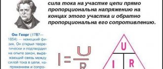
The operating principle of an electric motor of any design is based on the use of the law of electromagnetic induction and the phenomenon of self-induction.
Information. In a closed loop or frame placed in a magnetic field (MF) of permanent magnets, an electromotive force (EMF) arises. This occurs as a result of the frame being penetrated by electromagnetic lines of the magnetic field if the magnets or the frame itself are twisted.
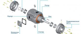
The operation of an electric motor is based on the generation of torque when voltage is applied to the armature coils. It is also called a synchronous direct current (DC) motor. The simplest machine contains:
- stator with permanent magnets located on it;
- two-prong armature having one winding;
- collector;
- brush assembly, which includes two brushes and two lamellas (plates).
Attention! Such an engine has two “dead points” (extreme positions). At these points, self-starting is impossible, and the torque of such a DC motor is uneven.
The stator, also known as an inductor, has basically two pairs of main poles. If necessary, additional ones are installed on it. This improves switching on the armature commutator.
The rotor, also known as the anchor, must have at least three teeth so that the engine can start itself from each point. In this case, one of the teeth consistently falls into the connection zone.
Scheme of a simple collector DPT
All existing armature coils are connected to the brush-collector assembly. The collector is a ring of insulated lamellas (plates) located along the length of the rotor axis. Brushes slide over them and apply or relieve tension.
Collector device
Important! The motor rotates due to the Ampere force, which acts on the conductor located in the MP when electric current flows in it. In this case, the current source must maintain its constant value.
All DPTs have self-regulating properties, maintaining the torque equal to the resistance moment on the shaft. This happens automatically and the rotation speed is constant.
Asynchronous electric motors
An AC motor (also known as an asynchronous motor) also uses a magnetic field to create torque. Its inventor is Russian electrical physicist, Mikhail Osipovich Dolivo-Dobrovolsky. The first example of an asynchronous electric motor appeared in 1890 (the theory and practice of using 3-phase alternating current began with it).
Design and arrangement of AC electric motors:
- 3 windings are wound on each stator;
- 1 of 3 phases is connected to each winding;
- To cool the windings, which become very hot, passing alternating currents through them, a cooler (fan) is installed on the end shaft of the electric motor.
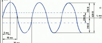
The flow of currents and voltage through a 3-phase network has a graphical form of a sinusoid (smooth change in operating parameters). The power in the winding smoothly increases as it moves from the end of the sine wave to its peak and decreases again, “descending” from the top to the other end, reaching its minimum at both ends, and its maximum at the top.
Principle of operation:
- the voltage supplied from 3 phases to the stator windings forms a magnetic field (its rotation frequency is equal to the rotation frequency in the network - 50 Hz);
- the rotor is located inside the inductor, and its own field also arises in it;
- The rotor field is repelled from the stator field, generating torque.
Due to the fact that AC electric motors use a short-circuited system, when the magnetic field of the stator and the rotor winding interact, a very large current is generated in the latter. It forms its own anchor field. Contacting according to the laws of mutual attraction/repulsion of the poles with the magnetic flux of the inductor, the rotor field sets the motor shaft in motion in a direction similar to the direction of this field.
The design of an AC electric motor on video
Why asynchronous?
The speed of the magnetic fields of the rotor and stator is similar, but the first is 8–100 degrees behind the second in phase, which ensures asynchronous operation of the main elements (hence the name). A feature of such electric motors is the creation of very large starting currents. This is typical for classic short-circuited devices (the ones whose lights flash when started). To reduce the risk of overloads during their operation, a number of measures are applied:
- in machines with high power ratings, a phase armature with three star-connected windings is used;
- The rotor windings are connected not directly to the electrical network, but through a collector (brushes, plates) connected to a starting rheostat.
As a result, when such an electric motor starts operating, it is connected to the power supply and the active resistance in the rotor circuit is progressively reduced to zero. There are no blinking, no power overloads – the AC motor starts smoothly.
Advantages of AC motors
Electric motors of the asynchronous type made it possible to operate a 3-phase network, which, in fact, is formed by three separate circuits with sinusoidal driving forces (EMF) in each of them. The EMFs in the phases have the same frequency, are created by one source (usually a 3-phase generator), but are shifted relative to each other by 120 degrees.
A 3-phase network is a balanced system with a constant instantaneous total power, and the AC motor that powers it has undeniable advantages. Among them:
- easy operation;
- low price;
- reliability;
- efficiency in terms of controlling torque and speed. It is ensured by the controllability of the electric motor (its dynamics) using a signal (digital or analog). Plus, a 3-phase motor can be "made" to rotate in any direction by changing the direction of the alternating current on the rotor winding.
Single-phase electric motors
Along with 3-phase motors, 1-phase asynchronous electric motors are also widely used in practice. They are electrical equipment powered from a household network with a voltage of 220 V (frequency - 50 Hz). Like the 3-phase analogue, it works to convert the received electricity into a mechanical action - rotation.
The design and principle of operation of a 1-phase motor is simpler:
- At least 2 windings are formed on the stator - starting and working;
- the axes of the windings must be shifted relative to each other by 90%;
- one more element is added to the design - a phase-shifting element (this can be a coil, capacitor or resistor);
- Power is supplied through the AC supply to the winding.
1-phase AC electric motors are installed on household appliances (from washing machine centrifuges to refrigerators) and low-power machines for manufacturing enterprises.
Comparison of single and three phase electric motors
Compared to 3-phase 1-phase asynchronous motors, they are somewhat inferior in a number of characteristics:
- the power of the former is at least 30% lower with similar dimensions;
- single-phase devices are not able to idle for more than 5–10 minutes;
- The overload capacity of three-phase ones is much higher.
UKD
The main advantage of a general-purpose commutator electric motor (which can be powered by direct current or alternating current) is its efficiency. The maximum torque and current consumption of such devices are limited due to inductive reactance at low speeds.
Motors with increased slip
A separate group of electric motors should include three-phase devices with increased resistance of the rotor winding, which ensures critical slip. It is 40% in mechanisms with increased sliding. They themselves are used in machines with high inertia, operating in the mode of frequent short-term starts.
Classification of electric motors
Electrical machines can be divided into two groups, paying attention to the peculiarities of the formation of torque: magnetoelectric and hysteresis. The second group is rarely used; in them, rotation occurs due to magnetization reversal of the rotor.
Stator - concept and principle of operation
Magnetoelectric motors are divided according to the type of current into models:
- direct current;
- pulsating current;
- alternating current;
- universal.
Motors are called universal because they can consume both direct and alternating current for operation.
DC motors
Despite the fact that such motors can be powered by both direct and alternating current, their windings are mainly supplied with constant voltage.
Attention! The phase switching method allows dividing the DC motor into collector and valve. The presence of feedback in current, voltage and speed allows for the presence of an adjustable electric drive.
Commutator machines have a problem area: the brush-collector unit (BCU), which creates difficulty in servicing and some unreliability in operation.
Internal structure of the collector DPT
Valve electric motors do not have a commutator; the phases are switched by an inverter (electronic unit). With such machines, feedback is possible through a rotor position sensor.
Valve DPT
Pulsating current motors
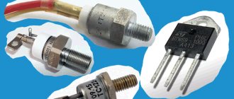
Similar devices are used on electric locomotives. The motor is powered by pulsating current. They are structurally distinguished from DBT by the following:
- presence of compensation winding;
- increased number of pole pairs;
- laminated additional poles;
- laminated inclusions into the frame.
For your information. Such a current is obtained as a result of the addition of two currents: direct and alternating, therefore it has both components. It does not change direction, but pulsates, briefly changing values from maximum to minimum and not in all cases to zero.
AC motors
According to the method of operation, such machines are divided into motors: synchronous and asynchronous.
Why synchronous? Because the speed of the rotor and the speed of the MP rotating in the stator are absolutely the same. In asynchronous motors, the speed of rotation of the motor in the stator is higher than that of the rotor.
PT motor
Universal commutator motor (UCM)
This type is used in power tools: cutting machine, drill, trimmer, etc. Indispensable where high speeds (above 3000 rpm), small sizes and low weight are needed. The motor operates from both types of current and has a series-connected field winding. The electronic circuit includes a linear voltage converter.
Attention! When using direct current with a voltage of 220V, the excitation winding is fully connected; with alternating current and the same voltage, the connection is partial.
Universal collector AC 220v SX7625
Synchronous reciprocating motor
The principle of operation of the electric motor is that permanent magnets are installed on the moving rod. A magnetic circuit with coils to which DC is supplied is built into the motor housing. The coils are installed so that the MF they create causes the rod to move back and forth.
Advantages and disadvantages of electric motors
Electric motors have significantly more advantages than disadvantages. Moreover, due to the improvement of both the design features of the electric drives themselves and the infrastructure associated with charging, many things that seemed critical yesterday are losing their relevance today.
Advantages
- No "swinging" required. The torque reaches its maximum immediately upon switching on. It is for this reason that the electric engine of an electric vehicle does not require starters and clutches - integral satellites of the internal combustion engine.
- Convenience. To engage reverse (that is, correction from the direction of rotation of the motor), it is enough to change the polarity; a complex gearbox is not required.
- High efficiency. For cars with electric motors it reaches 95%.
- Independence. At any speed mark, maximum torque is achieved.
- The motor is light weight. Manufacturers can easily afford to create compact cars.
- There are all possibilities for braking energy recovery. If in a car with an internal combustion engine the kinetic energy simply goes into the pads (and erases them), then in an electric car in recuperation mode the motor can function as a generator. In generation mode, electricity is simply transformed into another form and quickly accumulated in the battery. The solution is especially effective for vehicles with long braking distances. The volume of generated and accumulated energy is significantly influenced by the route (relief, in particular the presence of hilly sections on the road and the slope of the road).
- Reduced machine operating costs. Charging can be done from the mains. This is significantly cheaper than using diesel or gasoline. The benefit is obvious even in comparison with petrol economy class cars.
- Low noise level.
- In most cases, the motor does not require forced cooling.
- Environmental friendliness. Using electric vehicles reduces the amount of exhaust gases in the air.
Flaws
For a long time it was believed that the biggest disadvantage of using an electric motor is its dependence on batteries, which quickly fail.
This is no longer relevant. Modern batteries of electric cars, presented in mass production, guarantee a car mileage of 150-200 thousand km. The fact that cars with an electric motor are significantly inferior in power to gasoline ones has also lost relevance. The electric thrust of modern electric motors is no longer inferior to internal combustion engines. Therefore, it is now correct to reduce the shortcomings of electric motors not to design flaws, but to a poorly developed infrastructure for recharging electric vehicles. While in the USA and Scandinavia it is easy to recharge an electric car, until recently even in Western and Central Europe there were problems with the infrastructure for recharging such cars.
In Russia, Belarus, Ukraine, Kazakhstan, unfortunately, the situation with infrastructure is even worse. Although, for example, in Russia the number of gas stations for electric cars increased 3 times from 2022 to 2022, the coverage of charging areas is very heterogeneous. In Moscow it is denser, in the regions it is weaker. Even the gap with such giant cities as St. Petersburg and Chelyabinsk is colossal.
Use of asynchronous motors in a single-phase circuit
A distinctive feature when starting such a motor is manual activation. This is caused by the presence of a starting winding or a phase-shifting circuit. Unlike its three-phase counterpart, which starts automatically due to the shift of three phases, the single-phase one needs an initial push.
Single-phase motor connection diagram
Capacitors for starting an electric motor
Starting is achieved by briefly switching on an additional (starting) winding, which is switched on through a starting relay with a thermocouple or a PNVS-12 button (220V 10A).
For your information. You can also connect a three-phase asynchronous motor to a 220 V network. In this case, the windings are connected in a “star” or “triangle”. The ends of two windings are connected to the network, the end of the third is briefly connected to one of them through a high-capacity starting capacitor connected in series (to avoid combustion).
Scheme for connecting a three-phase motor to a single-phase network
To increase the power of an electric motor, the formula of which includes cosϕ, the power factor, and therefore the coefficient of performance (efficiency), a working capacitance is included in the circuit. It is always on. So, a 2 kW three-phase motor, when switched on in this way, will deliver only 45-60% of the declared power. The power of any three-phase motor is easy to calculate using the formula.
Operating principle
A three-phase winding is placed in the stator of an asynchronous motor, which creates a rotating magnetic field when a sinusoidal current passes. When the closed conductors of the rotor intersect, the magnetic field creates an electric current (emf occurs).
The alternating current in the conductor creates its own magnetic field, which tends to catch up with the stator field. The interaction of the fields causes the rotor to rotate, the rotation speed of which lags behind the rotation speed of the stator field by the amount of slip. The presence of this difference is the main condition for the rotation of the rotor of an asynchronous motor.
UKD: operating principle and characteristics
Operating principle of a synchronous generator
These are single-phase motors that operate at high speeds with any type of electrical input.
Scheme of a universal commutator motor
The answer to the question why such a device operates on alternating current is that the direction of the torque does not change. The polarity of the stator poles changes almost simultaneously with a change in the current direction in the armature winding.
Important! For this purpose, series excitation of the motor is used. Therefore, the field current and the armature current are the same.
Therefore, when positive and negative half-cycles change, both the current in the armature winding Ia and the magnetic flux F change almost simultaneously.
Connection diagram and characteristics of the UCD
Features of synchronous motors
All synchronous motors have the following advantages:
- They do not supply or consume reactive energy into the network. This allows them to be reduced in size while maintaining power. A typical synchronous motor is smaller than an asynchronous motor.
- Compared to asynchronous devices, they are less sensitive to voltage surges.
- Good overload resistance.
- Such electric machines are capable of maintaining a constant rotation speed if the load level does not exceed permissible limits.
In any barrel, there is a fly in the ointment. Synchronous electric motors have the following disadvantages:
- complex design;
- difficult starting;
- It is quite difficult to change the rotation speed (by changing the current frequency value).
The combination of all these features makes synchronous motors unprofitable at powers up to 100 W. But at higher levels of productivity, synchronous machines show themselves in all their glory.
Synchronous principle of operation of the electric motor
Features of synchronous operation of motors depend on which motor is being considered. They are:
- with excitation coils;
- with permanent magnets (PM);
- reactive;
- hysteresis;
- stepper.
There are hybrid models: reactive with PM and reactive-hysteresis.
Regardless of which motors are considered, the synchronism condition is based on the interaction of the MF poles of the inductor (stator) and the MF of the armature.
For your information. If the structural structure is reversed (position the armature and inductor in reverse), then the synchronous motor turns into a generator.
The engine operates as follows: direct current is applied to the field winding (from an external power source), and alternating current is applied to the three-phase armature winding. The armature winding creates a rotating MF, which interacts with the MF of the excitation winding. The result is an electromagnetic torque that rotates the rotor.
Operating principle of an electric motor
operating principle is based on the processes of mutual attraction and repulsion of like and opposite poles of magnets on the rotor (in motion) and stator (its magnet is stationary). In the simplest assembly of a DC electric motor, the coil assembly acts as a rotor, and the magnet itself acts as an inductor.
The magnetic field provides high efficiency with one refinement, which creates the complexity of the mechanism. To ensure constant movement of the armature, it is necessary to achieve an automatic change of its poles (so that when attracted to the opposite pole of a stationary magnet, it immediately changes its own pole). This is the only way to eliminate the “freezing” of the armature and ensure its non-stop movement under the influence of the magnetic field and inertia.
Magnetic field of an electric motor
The operating principle of a stator electric motor (also called an induction motor) is also based on the formation of a magnetic field from the stator. It is formed during the passage of currents through its windings. This field (rotating magnetic) forms the magnetic field of the rotor through the induction of currents in the windings of its conductors.
It (the stator field) creates its own magnetic flux, and a proportional relationship is observed:
- the stator magnetic field is proportional to the electrical voltage in the network;
- the magnetic flux produced by the rotating field is proportional to the current.
The characteristics of the stator field depend on the currents passing through the windings and the number of phase windings. The magnetic field of the rotor, in turn, also forms a flux that moves slower than the stator flux. Both flows (stator and armature) are mutually attracted, forcing the rotor to perform rotational movements.
This is how torque arises - the very key process for which the entire electric motor structure . Considering the role of the stator and rotor in the operation of an AC electric motor, it is easy to conclude that these 2 elements are of the greatest importance in its assembly.
Three-phase motor power formula
In order to determine engine power, the formula looks like this:
P=√3*U*I*cosϕ*η.
Ingredients of the formula:
- Un – rated voltage;
- Iн – rated current of the electric motor (according to the passport);
- Cosϕ – power factor (0.75-0.9);
- η – efficiency (0.7-0.85).
If the value of In is unknown, it must be found using the appropriate formula.
Asynchronous motors used for three-phase networks are the most stable and reliable machines. However, the AC frequency limit of 50 Hz does not allow them to reach rotation speeds of more than 3000 rpm. Therefore, universal commutator DFCs are an effective solution for mechanical processes that require the motor to be able to rotate the shaft at a higher frequency.
Asynchronous electric motors
In previous sections, we discussed why AC motors are also called induction motors, or squirrel wheel motors. Next, we will explain why they are also called asynchronous electric motors. In this case, the relationship between the number of poles and the number of revolutions made by the rotor of the electric motor is taken into account.
The rotation frequency of the magnetic field is generally considered to be the synchronous rotation frequency (Ns). The synchronous speed can be calculated as follows: line frequency (F) multiplied by 120 and divided by the number of poles (P).
If, for example, the mains frequency is 50 Hz, then the synchronous speed for a 2-pole electric motor is 3000 rpm.
The synchronous speed decreases as the number of poles increases.
The table below shows the synchronous speed for different numbers of poles. Synchronous speed for different number of poles
| Number of poles | Synchronous speed 50 Hz | Synchronous speed 60 Hz |
| 2 | 3000 | 3600 |
| 4 | 1500 | 1800 |
| 6 | 1000 | 1200 |
| 8 | 750 | 900 |
| 12 | 500 | 600 |
Climatic versions of electric motors
When choosing an electric motor, not only its technical characteristics are taken into account, but also the environmental conditions in which it will be operated.
Modern electric drives are available in different climatic versions. Categories are marked with corresponding letters and numbers:
- U - models for use in temperate climates;
- HL - electric motors adapted to cold climates;
- TS - versions for dry tropical climates;
- TV - versions for humid tropical climates;
- T - universal versions for tropical climates;
- О - electric motors for operation on land;
- M - engines for operation in marine climates (cold and temperate);
- B - models that can be used in any area on land and at sea.
The numbers in the model nomenclature indicate the type of its placement:
- 1 — possibility of operation in open areas;
- 2 — installation in rooms with free access of air;
- 3 — operation in closed workshops and premises;
- 4 — use in industrial and other premises with the ability to regulate climatic conditions (availability of ventilation, heating);
- 5 — versions designed for operation in areas of high humidity, with high condensation formation.